Table of Contents
Advertisement
Quick Links
Advertisement
Table of Contents

Related Manuals for IEI Technology NANO-ULT3


Summary of Contents for IEI Technology NANO-ULT3
-
Page 1: User Manual
NANO-ULT3 SBC NANO-ULT3 CPU Card MODEL: NANO-ULT3 EPIC SBC with 14nm Intel® Core™ i7/i5/i3 or Celeron® On-board SoC, LVDS, HDMI, iDP, Dual PCIe GbE, USB 3.0, PCIe Mini, SATA 6Gb/s, mSATA, RS-232/422/485, Audio, and RoHS User Manual Page I Rev. 1.00 - May 26, 2016... - Page 2 NANO-ULT3 SBC Revision Date Version Changes May 26, 2016 1.00 Initial release Page II...
- Page 3 NANO-ULT3 SBC Copyright COPYRIGHT NOTICE The information in this document is subject to change without prior notice in order to improve reliability, design and function and does not represent a commitment on the part of the manufacturer. In no event will the manufacturer be liable for direct, indirect, special, incidental, or consequential damages arising out of the use or inability to use the product or documentation, even if advised of the possibility of such damages.
-
Page 4: Manual Conventions
NANO-ULT3 SBC Manual Conventions WARNING Warnings appear where overlooked details may cause damage to the equipment or result in personal injury. Warnings should be taken seriously. CAUTION Cautionary messages should be heeded to help reduce the chance of losing data or damaging the product. -
Page 5: Table Of Contents
PTIONAL TEMS 3 CONNECTORS ......................14 3.1 P ..............15 ERIPHERAL NTERFACE ONNECTORS 3.1.1 NANO-ULT3 Layout ..................15 3.1.2 Peripheral Interface Connectors ..............15 3.1.3 External Interface Panel Connectors............... 17 3.2 I ..............17 NTERNAL ERIPHERAL ONNECTORS 3.2.1 +12V DC-IN Power Connector ............... 17 3.2.2 Audio Connector .................... - Page 6 NANO-ULT3 SBC 3.2.11 LVDS LCD Connector..................27 3.2.12 LAN LED Connectors ..................28 3.2.13 PCIe Mini Card Slot, Full-size ..............29 3.2.14 PCIe Mini Card Slot, Half-size ..............30 3.2.15 Power Button ....................32 3.2.16 Power Button Connector................32 3.2.17 Reset Button Connector ................. 33 3.2.18 RS-232 Serial Port Connectors..............
- Page 7 NANO-ULT3 SBC 4.6.5 LVDS Panel Resolution Select Switch ............. 58 4.6.6 LVDS Voltage Select Jumper................60 4.7 C .................... 61 HASSIS NSTALLATION 4.7.1 Heat Sink......................61 4.7.2 Motherboard Installation................. 62 4.8 I ............64 NTERNAL ERIPHERAL EVICE ONNECTIONS 4.8.1 AT Power Connection ..................64 4.8.2 Audio Kit Installation..................
- Page 8 NANO-ULT3 SBC 5.3.8 SATA Configuration ..................92 5.3.9 USB Configuration................... 94 5.3.10 IEI Feature ..................... 95 5.4 C ........................96 HIPSET 5.4.1 System Agent (SA) Configuration ..............96 5.4.1.1 Graphics Configuration................97 5.4.1.1.1 LCD Control ..................99 5.4.1.2 Memory Configuration ................101 5.4.2 PCH-IO Configuration ..................
- Page 9 NANO-ULT3 SBC List of Figures Figure 1-1: NANO-ULT3 .........................2 Figure 1-2: Connectors ........................4 Figure 1-3: Dimensions (mm) ......................5 Figure 1-4: Data Flow Diagram......................6 Figure 3-1: Connector and Jumper Locations................15 Figure 3-2: +12V DC-IN Power Connector Location..............18 Figure 3-3: Audio Connector Location ..................19 Figure 3-4: Battery Connector Location..................20...
- Page 10 NANO-ULT3 SBC Figure 3-28: USB Connector Location (Type A) ................42 Figure 3-29: External Peripheral Interface Connector ..............43 Figure 3-30: HDMI Connector Pinout Locations................44 Figure 3-31: LAN Connector......................44 Figure 4-1: SO-DIMM Installation ....................49 Figure 4-2: Removing the Retention Screw ................50 Figure 4-3: Inserting the Full-size PCIe Mini Card into the Slot at an Angle ......50 Figure 4-4: Securing the Full-size PCIe Mini Card ..............51...
- Page 11 NANO-ULT3 SBC List of Tables Table 1-1: NANO-ULT3 Model Variations ..................3 Table 1-2: Technical Specifications....................9 Table 3-1: Peripheral Interface Connectors ................17 Table 3-2: Rear Panel Connectors ....................17 Table 3-3: +12V DC-IN Power Connector Pinouts ..............18 Table 3-4: Audio Connector Pinouts ..................19 Table 3-5: Battery Connector Pinouts ..................20...
- Page 12 NANO-ULT3 SBC Table 3-30: USB 3.0 Port Pinouts....................45 Table 4-1: AT/ATX Mode Select Switch Settings...............54 Table 4-2: Flash Descriptor Security Override Jumper Settings..........56 Table 4-3: HDMI/DP Select Switch Settings ................57 Table 4-4: LVDS Panel Resolution Selection................59 Table 4-5: LVDS Voltage Select Jumper Settings ..............60...
- Page 13 NANO-ULT3 SBC List of BIOS Menus BIOS Menu 1: Main ........................73 BIOS Menu 2: Advanced ......................74 BIOS Menu 3: ACPI Settings .......................75 BIOS Menu 4: AMT Configuration....................76 BIOS Menu 5: F81866 Super IO Configuration ................77 BIOS Menu 6: Serial Port n Configuration .................78 BIOS Menu 7: iWDD H/W Monitor ....................81...
-
Page 15: Introduction
NANO-ULT3 SBC Chapter Introduction Page 1... -
Page 16: Introduction
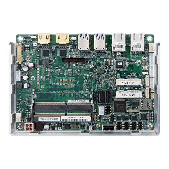
1.1 Introduction Figure 1-1: NANO-ULT3 The NANO-ULT3 series is an EPIC form factor single bard computer. It has an on-board 14nm Intel® Core™ i7/i5/i3 or Celeron® processor, and supports two 260-pin 2133/1866 MHz dual-channel DDR4 non-ECC unbuffered SDRAM SO-DIMM slots with up to 32.0 GB of memory. -
Page 17: Model Variations
NANO-ULT3 SBC 1.2 Model Variations The model variations of the NANO-ULT3 series are listed below. Model No. mSATA Intel® Core™ i7-6600U on-board SoC NANO-ULT3-i7-R10 Supported (up to 3.4 GHz, dual-core, 4 MB cache, TDP=15 W) Intel® Core™ i5-6300U on-board SoC... -
Page 18: Connectors
NANO-ULT3 SBC 1.4 Connectors The connectors on the NANO-ULT3 are shown in the figure below. Figure 1-2: Connectors Page 4... -
Page 19: Dimensions
NANO-ULT3 SBC 1.5 Dimensions The dimensions of the board are listed below: Figure 1-3: Dimensions (mm) Page 5... -
Page 20: Data Flow
NANO-ULT3 SBC 1.6 Data Flow Figure 1-4 shows the data flow between the system chipset, the CPU and other components installed on the motherboard. Figure 1-4: Data Flow Diagram Page 6... -
Page 21: Technical Specifications
NANO-ULT3 SBC 1.7 Technical Specifications NANO-ULT3 technical specifications are listed below. Specification NANO-ULT3 ® generation Intel mobile ULT on-board SoC: ® Intel Core™ i7-6600U on-board SoC (up to 3.4 GHz, dual-core, 4 MB cache, TDP=15 W) ® Intel Core™... - Page 22 Expansion 1 x Full-size PCIe Mini card slot (with SIM card socket and mSATA* support) ® ® * The NANO-ULT3-C SKU with Intel Celeron 3955U CPU does not support mSATA modules. Environmental and Power Specifications 12 V DC input only (AT/ATX support)
-
Page 23: Table 1-2: Technical Specifications
NANO-ULT3 SBC Specification NANO-ULT3 1 x Internal power connector by 4-pin (2x2) connector Power Connector ® +12 V @ 2.48 A (Intel Core™ i3-6100U with two 8 GB DDR4 Power Consumption memory) -20°C ~ 60°C Operating Temperature Storage Temperature -30°C ~ 70°C... -
Page 24: Unpacking
NANO-ULT3 SBC Chapter Unpacking Page 10... -
Page 25: Anti-Static Precautions
Only handle the edges of the PCB: Don't touch the surface of the motherboard. Hold the motherboard by the edges when handling. 2.2 Unpacking Precautions When the NANO-ULT3 is unpacked, please do the following: Follow the antistatic guidelines above. -
Page 26: Packing List
If any of the components listed in the checklist below are missing, do not proceed with the installation. Contact the IEI reseller or vendor the NANO-ULT3 was purchased from or contact an IEI sales representative directly by sending an email to sales@ieiworld.com. -
Page 27: Optional Items
NANO-ULT3 SBC One Key Recovery CD Quick Installation Guide 2.4 Optional Items The following are optional components which may be separately purchased: Item and Part Number Image KB/MS PS/2 Y-cable, 135 mm, p=2.0 (P/N: 32000-023800-RS) Dual USB cable (wo bracket), 210 mm, p=2.0... -
Page 28: Connectors
NANO-ULT3 SBC Chapter Connectors Page 14... -
Page 29: Peripheral Interface Connectors
NANO-ULT3 SBC 3.1 Peripheral Interface Connectors This chapter details all the jumpers and connectors. 3.1.1 NANO-ULT3 Layout The figures below show all the connectors and jumpers. Figure 3-1: Connector and Jumper Locations 3.1.2 Peripheral Interface Connectors The table below lists all the connectors on the board. - Page 30 NANO-ULT3 SBC Battery connector 2-pin wafer BAT1 Buzz connector 2-pin wafer Digital I/O connector 10-pin header DIO1 Debug card connector 12-pin wafer DBG_PORT1 Fan connector, CPU 4-pin wafer CPU/FAN1 Fan connector, system 4-pin wafer SYS/FAN1 Front panel connector 6-pin wafer...
-
Page 31: External Interface Panel Connectors
USB 3.0 connectors USB 3.0 USB_CON1, USB_CON2 Table 3-2: Rear Panel Connectors 3.2 Internal Peripheral Connectors The section describes all of the connectors on the NANO-ULT3. 3.2.1 +12V DC-IN Power Connector CN Label: CN10 CN Type: 4-pin Molex, p=4.2 mm... -
Page 32: Audio Connector
NANO-ULT3 SBC Figure 3-2: +12V DC-IN Power Connector Location PIN NO. DESCRIPTION PIN NO. DESCRIPTION +12V +12V Table 3-3: +12V DC-IN Power Connector Pinouts 3.2.2 Audio Connector CN Label: AUDIO1 CN Type: 10-pin header, p=2.00 mm CN Location: See Figure 3-3... -
Page 33: Battery Connector
NANO-ULT3 SBC Figure 3-3: Audio Connector Location PIN NO. DESCRIPTION PIN NO. DESCRIPTION LINE_OUTR LINEIN_R ANALOG_GND ANALOG_GND LINE_OUTL LINEIN_L ANALOG_GND ANALOG_GND MICIN1 MICIN2 Table 3-4: Audio Connector Pinouts 3.2.3 Battery Connector CAUTION: Risk of explosion if battery is replaced by an incorrect type. Only certified engineers should replace the on-board battery. -
Page 34: Buzzer Connector
NANO-ULT3 SBC CN Pinouts: See Table 3-5 The battery connector is connected to the system battery. The battery provides power to the system clock to retain the time when power is turned off. Figure 3-4: Battery Connector Location Description VBAT+ Table 3-5: Battery Connector Pinouts 3.2.4 Buzzer Connector... -
Page 35: Digital I/O Connector
NANO-ULT3 SBC Figure 3-5: Buzzer Connector Location Description Buzzer+ Buzzer- Table 3-6: Buzzer Connector Pinouts 3.2.5 Digital I/O Connector CN Label: DIO1 CN Type: 10-pin header, p=2.00 mm CN Location: See Figure 3-6 See Table 3-7 CN Pinouts: The 8-bit digital I/O connector provides programmable input and output for external devices. -
Page 36: Fan Connectors
NANO-ULT3 SBC PIN NO. DESCRIPTION PIN NO. DESCRIPTION DOUT3 DOUT2 DOUT1 DOUT0 DIN3 DIN2 DIN1 DIN0 Table 3-7: Digital I/O Connector Pinouts 3.2.6 Fan Connectors CN Label: CPU/FAN1, SYS/FAN1 CN Type: 4-pin wafer, p=2.54 mm CN Location: See Figure 3-7... -
Page 37: Front Panel Connector
NANO-ULT3 SBC 3.2.7 Front Panel Connector CN Label: CN11 6-pin wafer, p=2.00 mm CN Type: CN Location: See Figure 3-8 CN Pinouts: See Table 3-9 The front panel connector connects to the power LED indicator and HDD LED indicator on the system front panel. -
Page 38: Internal Displayport Connector
NANO-ULT3 SBC 3.2.8 Internal DisplayPort Connector NOTE: The iDP connector is disabled by default since the iDP connector is co-lay with the HDMI1 connector. To enable the iDP connector, use the HDMI/DP select switch to configure the settings. Please refer to Section 4.6.4 for detailed information. -
Page 39: Keyboard And Mouse Connector
NANO-ULT3 SBC Description Description Lane2+ Lane3+ Lane2- Lane3- Lane0+ Lane1+ Lane0- Lane1- VCC3 VCC5 Table 3-10: Internal DisplayPort Connector Pinouts 3.2.9 Keyboard and Mouse Connector CN Label: KB/MS1 6-pin wafer, p=2.00 mm CN Type: CN Location: See Figure 3-10 CN Pinouts:... -
Page 40: Lvds Backlight Inverter Connector
NANO-ULT3 SBC Description Mouse Clock Keyboard Data Keyboard Clock Table 3-11: Keyboard and Mouse Connector Pinouts 3.2.10 LVDS Backlight Inverter Connector CN Label: INV1 5-pin wafer, p=2.00 mm CN Type: CN Location: See Figure 3-11 CN Pinouts: See Table 3-12 The backlight inverter connector provides power to an LCD panel. -
Page 41: Lvds Lcd Connector
NANO-ULT3 SBC 3.2.11 LVDS LCD Connector CN Label: 30-pin crimp, p=1.25 mm CN Type: CN Location: See Figure 3-12 CN Pinouts: See Table 3-13 The LVDS connector is for an LCD panel to connect to the board. Figure 3-12: LVDS Connector Location... -
Page 42: Lan Led Connectors
NANO-ULT3 SBC Description Description +LCD VCC +LCD VCC +LCD VCC +LCD VCC Table 3-13: LVDS Connector Pinouts 3.2.12 LAN LED Connectors CN Label: JP1, JP2 CN Type: 2-pin header, p=2.00 mm CN Location: See Figure 3-13 CN Pinouts: See Table 3-14 The LAN LED connectors connect to the LAN link LEDs on the system. -
Page 43: Pcie Mini Card Slot, Full-Size
3955U CPU does not support mSATA modules. 2. If the mSATA module installed on the NANO-ULT3 can not be detected, please set CN8 as an mSATA slot manually in BIOS option (Chipset > PCH-IO Configuration > PCI Express Configuration > Full Size PCIE Mini Card Selection). -
Page 44: Pcie Mini Card Slot, Half-Size
NANO-ULT3 SBC Description Description 1.5 V VCC3 SIM_VCC SIM_IO CLK- SIM_CLK CLK+ SIM_RST SIM_VPP BUF_PLT_RST# VCC3 BUF_PLT_RST# SATA_RXN2_C VCC3 SATA_RXP2_C 1.5 V SMBCLK SATA_TXN2 SMBDATA SATA_TXP2 USB7- USB7+ VCC3 VCC3 RF_LINK# BLUELED# 1.5 V M-SATADET VCC3 Table 3-15: Full-size PCIe Mini Card Slot Pinouts 3.2.14 PCIe Mini Card Slot, Half-size... -
Page 45: Figure 3-15: Half-Size Pcie Mini Slot Location
NANO-ULT3 SBC The PCIe Mini card slot is for installing a half-size PCIe Mini expansion card with USB interface. Figure 3-15: Half-size PCIe Mini Slot Location Description Description PCIE_WAKE# VCC3 1.5 V VCC3 CLK_PCIE_MINI2_N CLK_PCIE_MINI2_P BUF_PLT_RST# VCC3 BUF_PLT_RST# PCIE_RX4DN VCC3 PCIE_RX4DP 1.5V... -
Page 46: Power Button
NANO-ULT3 SBC Description Description RF_LINK# BLUELED# 1.5 V VCC3 Table 3-16: Half-size PCIe Mini Slot Pinouts 3.2.15 Power Button CN Label: PWR_SW1 CN Type: Push button CN Location: See Figure 3-16 The on-board power button controls system power. Figure 3-16: Power Button Location 3.2.16 Power Button Connector... -
Page 47: Reset Button Connector
NANO-ULT3 SBC Figure 3-17: Power Button Connector Location Description PWR_BTN+ PWR_BTN- Table 3-17: Power Button Connector Pinouts 3.2.17 Reset Button Connector CN Label: RST_BTN1 CN Type: 2-pin wafer, p=2.00 mm CN Location: See Figure 3-18 CN Pinouts: See Table 3-18 The reset button connector is connected to a reset switch on the system chassis to enable users to reboot the system when the system is turned on. -
Page 48: Serial Port Connectors
NANO-ULT3 SBC Description RESET+ RESET- Table 3-18: Reset Button Connector Pinouts 3.2.18 RS-232 Serial Port Connectors CN Label: COM1, COM2 CN Type: 10-pin header, p=2.00 mm CN Location: See Figure 3-19 CN Pinouts: See Table 3-19 The serial connector provides RS-232 connection. -
Page 49: Rs-232/422/485 Serial Port Connector
NANO-ULT3 SBC 3.2.19 RS-232/422/485 Serial Port Connector CN Label: COM3 10-pin header, p=2.00 mm CN Type: CN Location: See Figure 3-20 CN Pinouts: See Table 3-20 This connector provides RS-232, RS-422 or RS-485 communications. The default mode is set to RS-232 in BIOS. To configure the connector as RS-422 or RS-485, please refer to Section 5.3.3.1.3. -
Page 50: Sata 6Gb/S Drive Connectors
NANO-ULT3 SBC Use the optional RS-422/485 cable to connect to a serial device. The pinouts of the DB-9 connector are listed below. RS-422 Pinouts RS-485 Pinouts Table 3-21: DB-9 RS-422/485 Pinouts 3.2.20 SATA 6Gb/s Drive Connectors CN Label: SATA1, SATA2... -
Page 51: Sata Power Connectors
NANO-ULT3 SBC 3.2.21 SATA Power Connectors CN Label: SATA_PWR1, SATA_PWR2 CN Type: 2-pin wafer, p=2.00 mm CN Location: See Figure 3-22 CN Pinouts: See Table 3-22 The SATA power connector provides +5 V power output to the SATA connector. Figure 3-22: SATA Power Connector Locations... -
Page 52: Sim Card Slot
NANO-ULT3 SBC Figure 3-23: SMBus Connector Location Description SMB_DATA SMB_CLK Table 3-23: SMBus Connector Pinouts 3.2.23 SIM Card Slot CN Label: SIM1 CN Type: SIM card slot CN Location: See Figure 3-24 The SIM card slot accepts a SIM card for 3G network communication. -
Page 53: Spi Flash Connector, Bios
NANO-ULT3 SBC 3.2.24 SPI Flash Connector, BIOS CN Label: JSPI1 6-pin wafer, p=1.25 mm CN Type: CN Location: See Figure 3-25 CN Pinouts: See Table 3-24 The 6-pin SPI Flash connector is used to flash the BIOS. Figure 3-25: SPI Flash Connector Location Description +3.3VA... -
Page 54: Usb Connector
NANO-ULT3 SBC The 6-pin SPI Flash connector is used to flash the embedded controller. Figure 3-26: SPI Flash Connector Location Description +3.3VA SPI_CS#0_CN_EC SPI_SO_SW_EC SPI_CLK_SW_EC SPI_SI_SW_EC Table 3-25: SPI Flash Connector Pinouts 3.2.26 USB Connector CN Label: USB1 CN Type: 8-pin header, p=2.00 mm... -
Page 55: Usb Connector, Type A
NANO-ULT3 SBC Figure 3-27: USB Connector Location PIN NO. DESCRIPTION PIN NO. DESCRIPTION DATA4- DATA5+ DATA4+ DATA5- Table 3-26: USB Connector Pinouts 3.2.27 USB Connector, Type A CN Label: USB2 CN Type: USB Type A CN Location: See Figure 3-27... -
Page 56: External Peripheral Interface Connector Panel
Description DATA6+ DATA6- Table 3-27: USB Connector Pinouts (Type A) 3.3 External Peripheral Interface Connector Panel Figure 3-29 shows the NANO-ULT3 external peripheral interface connector (EPIC) panel. The EPIC panel consists of the following: 2 x GbE connector ... -
Page 57: Hdmi Connectors
NANO-ULT3 SBC Figure 3-29: External Peripheral Interface Connector 3.3.1 HDMI Connectors CN Label: HDMI1, HDMI2 CN Type: HDMI connector CN Location: See Figure 3-29 See Table 3-28 CN Pinouts: The HDMI connectors can connect to HDMI devices. Description Description HDMI_DATA2... -
Page 58: Lan Connectors
NANO-ULT3 SBC Figure 3-30: HDMI Connector Pinout Locations NOTE: The HDMI1 connector is co-lay with the iDP connector. When the iDP connector is enabled, the HDMI1 connector will be disabled. This is controlled by the HDMI/DP select switch. Please refer to Section 4.6.4 for detailed information. -
Page 59: Usb Connectors
F igure 3-29 CN Pinouts: See Table 3-30 The NANO-ULT3 has four external USB 3.0 ports. The USB connector can be connected to a USB 2.0 or USB 3.0 device. The pinouts of USB 3.0 connectors are shown below. Description... -
Page 60: Installation
NANO-ULT3 SBC Chapter Installation Page 46... -
Page 61: Anti-Static Precautions
Electrostatic discharge (ESD) can cause serious damage to electronic components, including the NANO-ULT3. Dry climates are especially susceptible to ESD. It is therefore critical that whenever the NANO-ULT3 or any other electrical component is handled, the following anti-static precautions are strictly adhered to. - Page 62 Turn all power to the NANO-ULT3 off: When working with the NANO-ULT3, make sure that it is disconnected from all power supplies and that no electricity is being fed into the system. Before and during the installation of the NANO-ULT3 DO NOT: ...
-
Page 63: So-Dimm Installation
NANO-ULT3 SBC 4.3 SO-DIMM Installation To install an SO-DIMM, please follow the steps below and refer to Figure 4-1. Figure 4-1: SO-DIMM Installation Step 1: Locate the SO-DIMM socket. Place the board on an anti-static mat. Step 2: Align the SO-DIMM with the socket. Align the notch on the memory with the notch on the memory socket. -
Page 64: Figure 4-2: Removing The Retention Screw
NANO-ULT3 SBC Figure 4-2: Removing the Retention Screw Step 3: Insert into the socket at an angle. Line up the notch on the card with the notch on the slot. Slide the PCIe Mini card into the socket at an angle of about 20º... -
Page 65: Half-Size Pcie Mini Card Installation
NANO-ULT3 SBC Figure 4-4: Securing the Full-size PCIe Mini Card 4.4.2 Half-size PCIe Mini Card Installation To install a half-size PCIe Mini card, please follow the steps below. Step 1: Locate the half-size PCIe Mini card slot. See Chapter 3. -
Page 66: Figure 4-6: Inserting The Half-Size Pcie Mini Card Into The Slot At An Angle
NANO-ULT3 SBC Step 3: Insert into the socket at an angle. Line up the notch on the card with the notch on the slot. Slide the PCIe Mini card into the slot at an angle of about 20º (Figure 4-6). -
Page 67: Sim Card Installation
NANO-ULT3 SBC 4.5 SIM Card Installation To install a SIM card, please follow the steps below. Step 1: Locate the SIM card slot. See Section 3.2.23. Step 2: Unlock the SIM card slot cover by sliding the cover in the direction as shown by the arrow in Figure 4-8. -
Page 68: System Configuration
NANO-ULT3 SBC Step 4: Close the slot cover and lock it by sliding it in the direction as shown by the arrow in Figure 4-10. Figure 4-10: Lock SIM Card Slot Cover 4.6 System Configuration The system configuration is controlled by buttons, jumpers and switches. The system configuration should be performed before installation. -
Page 69: Clear Cmos Button
CN Location: See Figure 4-12 If the NANO-ULT3 fails to boot due to improper BIOS settings, use the button to clear the CMOS data and reset the system BIOS information. The location of the clear CMOS button is shown in Figure 4-12... -
Page 70: Flash Descriptor Security Override Jumper
NANO-ULT3 SBC 4.6.3 Flash Descriptor Security Override Jumper CN Label: ME_FLASH1 CN Type: 2-pin header, p=2.00 mm CN Location: See Figure 4-13 CN Settings: See Table 4-2 The Flash Descriptor Security Override jumper (ME_FLASH1) allows to enable or disable the ME firmware update. Refer to Figure 4-13 and Table 4-2 for the jumper location and settings. -
Page 71: Hdmi/Dp Select Switch
NANO-ULT3 SBC Step 2: Update the BIOS and ME firmware, and then turn off the system power. Step 3: Remove the metal clip on the Flash Descriptor Security Override jumper to its default setting. Step 4: Restart the system. The system will reboot 2 ~ 3 times to complete the ME firmware update.Step 0:... -
Page 72: Lvds Panel Resolution Select Switch
NANO-ULT3 SBC Figure 4-14: HDMI/DP Select Switch Location 4.6.5 LVDS Panel Resolution Select Switch Jumper Label: Jumper Type: DIP switch Jumper Settings: See Table 4-4 Jumper Location: See Figure 4-15 Selects the resolution of the LCD panel connected to the LVDS connector. -
Page 73: Figure 4-15: Lvds Panel Resolution Select Switch Location
NANO-ULT3 SBC SW1 (4-3-2-1) Description 0111 1366x768 18-bit S 1000 1366x768 24-bit S 1001 1440x960 24-bit D 1010 1400x1050 24-bit D 1011 1600x900 24-bit D 1100 1680x1050 24-bit D 1101 1600x1200 24-bit D 1110 1920x1080 24-bit D 1111 1920x1200 24-bit D... -
Page 74: Lvds Voltage Select Jumper
4.6.6 LVDS Voltage Select Jumper WARNING: Permanent damage to the screen and NANO-ULT3 may occur if the wrong voltage is selected with this jumper. Please refer to the user guide that came with the monitor to select the correct voltage. -
Page 75: Chassis Installation
using copper pillars to hold the board up from the chassis When the NANO-ULT3 is shipped, a heat sink is secured to the board with six retention screws. If the NANO-ULT3 must be removed from the heat sink, the six retention screws must be removed. -
Page 76: Motherboard Installation
Figure 4-17: Heat Sink Retention Screws 4.7.2 Motherboard Installation Each side of the heat sink enclosure has several screw holes allowing the NANO-ULT3 to be mounted into a chassis (please refer to Figure 1-3 for the detailed dimensions). The user can design or select a chassis that has screw holes matching up with the holes on the heat sink enclosure for installing the NANO-ULT3. -
Page 77: Figure 4-18: Motherboard Installation Example
NANO-ULT3 SBC Figure 4-18: Motherboard Installation Example Page 63... -
Page 78: Internal Peripheral Device Connections
This section outlines the installation of peripheral devices to the on-board connectors 4.8.1 AT Power Connection Follow the instructions below to connect the NANO-ULT3 to an AT power supply. WARNING: Disconnect the power supply power cord from its AC power source to prevent a sudden power surge to the NANO-ULT3. -
Page 79: Audio Kit Installation
Figure 4-20: Connect Power Cable to Power Supply 4.8.2 Audio Kit Installation The Audio Kit that came with the NANO-ULT3 connects to the audio connector on the NANO-ULT3. The audio kit consists of three audio jacks. Mic-in connects to a microphone. -
Page 80: Cable Connection
NANO-ULT3 SBC Figure 4-21: Audio Kit Cable Connection Step 3: Connect the audio devices. Connect speakers to the line-out audio jack. Connect the output of an audio device to the line-in audio jack. Connect a microphone to the mic-in audio jack.Step 0:... -
Page 81: Sata Drive Connection
Step 0: 4.8.4 SATA Drive Connection The NANO-ULT3 is shipped with a SATA drive cable. To connect the SATA drive to the connector, please follow the steps below. Step 1: Locate the SATA connector and the SATA power connector. The locations of the connectors are shown in Chapter 3. -
Page 82: Figure 4-23: Sata Drive Cable Connection
NANO-ULT3 SBC Figure 4-23: SATA Drive Cable Connection Step 3: Connect the cable to the SATA disk. Connect the connector on the other end of the cable to the connector at the back of the SATA drive. See Figure 4-23. -
Page 83: Intel ® Amt Setup Procedure
® 4.9 Intel AMT Setup Procedure The NANO-ULT3 is featured with the Intel® Active Management Technology (AMT). To enable the Intel® AMT function, follow the steps below. Step 1: Make sure at least one of the memory sockets is installed with a DDR4 SO-DIMM. -
Page 84: Bios
NANO-ULT3 SBC Chapter BIOS Page 70... -
Page 85: Introduction
NANO-ULT3 SBC 5.1 Introduction The BIOS is programmed onto the BIOS chip. The BIOS setup program allows changes to certain system settings. This chapter outlines the options that can be changed. NOTE: Some of the BIOS options may vary throughout the life cycle of the product and are subject to change without prior notice. -
Page 86: Getting Help
NANO-ULT3 SBC Function Decrease the numeric value or make changes F1 key General help, only for Status Page Setup Menu and Option Page Setup Menu F2 key Load previous values. F3 key Load optimized defaults F4 key Save changes and Exit BIOS Esc key Main Menu –... -
Page 87: Main
NANO-ULT3 SBC 5.2 Main The Main BIOS menu (BIOS Menu 1) appears when the BIOS Setup program is entered. Aptio Setup Utility – Copyright (C) 2016 American Megatrends, Inc. Main Advanced Chipset Security Boot Save & Exit BIOS Information BIOS Vendor American Megatrends Set the Date. -
Page 88: Advanced
NANO-ULT3 SBC The System Overview field also has two user configurable fields: System Date [xx/xx/xx] Use the System Date option to set the system date. Manually enter the day, month and year. System Time [xx:xx:xx] Use the System Time option to set the system time. Manually enter the hours, minutes and seconds. -
Page 89: Acpi Settings
NANO-ULT3 SBC 5.3.1 ACPI Settings The ACPI Settings menu ( B IOS Menu 3) configures the Advanced Configuration and Power Interface (ACPI) options. Aptio Setup Utility – Copyright (C) 2016 American Megatrends, Inc. Advanced ACPI Settings Select the highest ACPI... -
Page 90: Amt Configuration
NANO-ULT3 SBC 5.3.2 AMT Configuration The AMT Configuration menu (BIOS Menu 4) allows Intel® Active Management Technology (AMT) options to be configured. Aptio Setup Utility – Copyright (C) 2016 American Megatrends, Inc. Advanced Intel AMT [Enabled] Enable/Disable Intel (R) Un-configure ME... -
Page 91: F81866 Super Io Configuration
NANO-ULT3 SBC Enabled To perform ME unconfigure 5.3.3 F81866 Super IO Configuration Use the F81866 Super IO Configuration menu (BIOS Menu 5) to set or change the configurations for the serial ports. Aptio Setup Utility – Copyright (C) 2016 American Megatrends, Inc. -
Page 92: Serial Port N Configuration
NANO-ULT3 SBC 5.3.3.1 Serial Port n Configuration Use the Serial Port n Configuration menu (BIOS Menu 6) to configure the serial port n. Aptio Setup Utility – Copyright (C) 2016 American Megatrends, Inc. Advanced Serial Port 1 Configuration Enable or Disable Serial... -
Page 93: Serial Port 2 Configuration
NANO-ULT3 SBC IO=3F8h; IRQ=3, Serial Port I/O port address is 3F8h and the 4,5,6,7,9,10,11,12 interrupt address is IRQ3,4,5,6,7,9,10,11,12 Serial Port I/O port address is 2F8h and the IO=2F8h; IRQ=3, interrupt address is IRQ3,4,5,6,7,9,10,11,12 4,5,6,7,9,10,11,12 IO=3E8h; IRQ=3, Serial Port I/O port address is 3E8h and the... -
Page 94: Serial Port 3 Configuration
NANO-ULT3 SBC IO=2E8h; IRQ=3, Serial Port I/O port address is 2E8h and the 4,5,6,7,9,10,11,12 interrupt address is IRQ3,4,5,6,7,9,10,11,12 5.3.3.1.3 Serial Port 3 Configuration Serial Port [Enabled] Use the Serial Port option to enable or disable the serial port. -
Page 95: Iwdd H/W Monitor
NANO-ULT3 SBC Device Mode [RS232] Use the Device Mode option to select the Serial Port 3 signaling mode. Serial Port 3 signaling mode is RS-422 RS422 RS232 Serial Port 3 signaling mode is RS-232 EFAULT RS485 Serial Port 3 signaling mode is RS-485 5.3.4 iWDD H/W Monitor... -
Page 96: Smart Fan Mode Configuration
NANO-ULT3 SBC System temperature Fan Speed: CPU Fan Speed System Fan Speed Voltages CPU_CORE +12V +DDR +5VSB +3.3V +3.3VSB 5.3.4.1 Smart Fan Mode Configuration Use the Smart Fan Mode Configuration submenu (BIOS Menu 8) to configure fan temperature and speed settings. - Page 97 NANO-ULT3 SBC Manual Mode The fan spins at the speed set in the Manual EFAULT Mode option The fan adjusts its speed using these Auto Mode EFAULT settings: Auto mode fan start temperature Auto mode fan off temperature...
- Page 98 NANO-ULT3 SBC value, select the Auto mode fan start temperature option and enter a decimal number between 1 and 100. Auto mode fan off temperature [40] WARNING: Setting this value too high may cause the fan to speed up only when the CPU is at a very high temperature and therefore cause the system to be damaged.
-
Page 99: Rtc Wake Settings
NANO-ULT3 SBC 5.3.5 RTC Wake Settings The RTC Wake Settings menu (BIOS Menu 9) configures RTC wake event. Aptio Setup Utility – Copyright (C) 2016 American Megatrends, Inc. Advanced Wake system with Fixed Time [Disabled] Enable or disable System wake on alarm event. When... -
Page 100: Serial Port Console Redirection
NANO-ULT3 SBC Wake up second After setting the alarm, the computer turns itself on from a suspend state when the alarm goes off. 5.3.6 Serial Port Console Redirection The Serial Port Console Redirection menu (BIOS Menu 10) allows the console redirection options to be configured. -
Page 101: Legacy Console Redirection Settings
NANO-ULT3 SBC 5.3.6.1 Legacy Console Redirection Settings The Legacy Console Redirection Settings menu ( B IOS Menu 11) allows the legacy console redirection options to be configured. Aptio Setup Utility – Copyright (C) 2016 American Megatrends, Inc. Advanced Select a COM port to... -
Page 102: Console Redirection Settings
NANO-ULT3 SBC 5.3.6.2 Console Redirection Settings The Console Redirection Settings menu ( B IOS Menu 12) allows the console redirection options to be configured. The option is active when Console Redirection option is enabled. Aptio Setup Utility – Copyright (C) 2016 American Megatrends, Inc. - Page 103 NANO-ULT3 SBC Bits per second [115200] Use the Bits per second option to specify the serial port transmission speed. The speed must match the other side. Long or noisy lines may require lower speeds. 9600 Sets the serial port transmission speed at 9600.
-
Page 104: Cpu Configuration
NANO-ULT3 SBC Stop Bits [1] Use the Stop Bits option to specify the number of stop bits used to indicate the end of a serial data packet. Communication with slow devices may require more than 1 stop bit. ... - Page 105 NANO-ULT3 SBC Active Processor Cores [All] Use the Active Processor Cores BIOS option to enable numbers of cores in the processor package. Enable all cores in the processor package. EFAULT Enable one core in the processor package.
-
Page 106: Sata Configuration
NANO-ULT3 SBC 5.3.8 SATA Configuration Use the SATA Configuration menu (BIOS Menu 14) to change and/or set the configuration of the SATA devices installed in the system. Aptio Setup Utility – Copyright (C) 2016 American Megatrends, Inc. Advanced SATA Configuration... - Page 107 NANO-ULT3 SBC NOTE: Before accessing the RAID configuration utility, ensure to set the Option ROM Messages BIOS option in the Boot menu to Force BIOS. This is to allow the “Press <CTRL+I> to enter Configuration Utility……” message to appear during POST. Press Ctrl+I when prompted to enter the RAID configuration utility.
-
Page 108: Usb Configuration
NANO-ULT3 SBC 5.3.9 USB Configuration Use the USB Configuration menu (BIOS Menu 15) to read USB configuration information and configure the USB settings. Aptio Setup Utility – Copyright (C) 2016 American Megatrends, Inc. Advanced USB Configuration Enables Legacy USB support. AUTO option... -
Page 109: Iei Feature
NANO-ULT3 SBC Enabled Legacy USB support enabled EFAULT Legacy USB support disabled Disabled Auto Legacy USB support disabled if no USB devices are connected 5.3.10 IEI Feature Use the IEI Feature menu (BIOS Menu 16) to configure One Key Recovery function. -
Page 110: Chipset
NANO-ULT3 SBC 5.4 Chipset Use the Chipset menu (BIOS Menu 17) to configure the system chipset. Aptio Setup Utility – Copyright (C) 2016 American Megatrends, Inc. Main Advanced Chipset Boot Security Save & Exit Server Mgmt > System Agent (SA) Configuration System Agent (SA) >... -
Page 111: Graphics Configuration
NANO-ULT3 SBC VT-d [Disabled] Use the VT-d option to enable or disable VT-d support. Disable VT-d support. Disabled EFAULT Enabled Enable VT-d support. 5.4.1.1 Graphics Configuration Use the Graphics Configuration menu ( B IOS Menu 19) to configure the graphics settings. - Page 112 NANO-ULT3 SBC Internal Graphics [Enabled] Use the Internal Graphics option to enable or disable the internal graphics device. The internal graphics device is automatically detected Auto and enabled. Disable the internal graphics device. Disabled Enabled Enable the internal graphics device. The following...
-
Page 113: Lcd Control
NANO-ULT3 SBC 5.4.1.1.1 LCD Control Use the LCD Control submenu (BIOS Menu 20) to select a display device which will be activated during POST. Aptio Setup Utility – Copyright (C) 2016 American Megatrends, Inc. Chipset LCD Control Select the Video Device... - Page 114 NANO-ULT3 SBC On board LVDS [Enabled] Use the On board LVDS option enables or disables the on-board LVDS connector. The on-board LVDS connector is disabled. Disabled Enabled The on-board LVDS connector is disabled. EFAULT Backlight Control Mode [LED] Use the Backlight Control Mode option to specify the backlight control mode.
-
Page 115: Memory Configuration
NANO-ULT3 SBC 5.4.1.2 Memory Configuration Use the Memory Configuration submenu ( B IOS Menu 21) to display the memory information. Aptio Setup Utility – Copyright (C) 2016 American Megatrends, Inc. Chipset Memory Information Total Memory 4096 MB DIMM1 4096 MB --------------------- : Select Screen... -
Page 116: Pci Express Configuration
NANO-ULT3 SBC Restore AC Power Loss [Last State] Use the Restore AC Power BIOS option to specify what state the system returns to if there is a sudden loss of power to the system. Power Off The system remains turned off ... - Page 117 NANO-ULT3 SBC The MINI-PCIE (Half size) and MINI-PCIE (Full size) submenus both contain the following options: PCIe Speed [Auto] Use the PCIe Speed option to configure the PCIe interface speed. Auto EFAULT Gen 1 Gen 2 ...
-
Page 118: Hd Audio Configuration
NANO-ULT3 SBC 5.4.2.2 HD Audio Configuration Use the HD Audio Configuration submenu (BIOS Menu 24) to configure the High Definition Audio codec. Aptio Setup Utility – Copyright (C) 2016 American Megatrends, Inc. Chipset HD Audio Configuration Control Detection of the Azalia device. -
Page 119: Security
NANO-ULT3 SBC 5.5 Security Use the Security menu (BIOS Menu 25) to set system and user passwords. Aptio Setup Utility – Copyright (C) 2016 American Megatrends, Inc. Main Advanced Chipset Security Boot Save & Exit Password Description Set Administrator Password If ONLY the Administrator’s password is set,... -
Page 120: Boot
NANO-ULT3 SBC 5.6 Boot Use the Boot menu (BIOS Menu 26) to configure system boot options. Aptio Setup Utility – Copyright (C) 2016 American Megatrends, Inc. Main Advanced Chipset Security Boot Save & Exit Boot Configuration Select the keyboard Bootup NumLock State... - Page 121 NANO-ULT3 SBC Quiet Boot [Enabled] Use the Quiet Boot BIOS option to select the screen display when the system boots. Normal POST messages displayed Disabled Enabled OEM Logo displayed instead of POST messages EFAULT UEFI Boot [Disabled] Use the UEFI Boot option to enable or disable to boot from the UEFI devices.
-
Page 122: Exit
NANO-ULT3 SBC 5.7 Exit Use the Exit menu (BIOS Menu 27) to load default BIOS values, optimal failsafe values and to save configuration changes. Aptio Setup Utility – Copyright (C) 2016 American Megatrends, Inc. Main Advanced Chipset Security Boot Save & Exit... - Page 123 NANO-ULT3 SBC Save as User Defaults Use the Save as User Defaults option to save the changes done so far as user defaults. Restore User Defaults Use the Restore User Defaults option to restore the user defaults to all the setup options.
-
Page 124: Software Drivers
NANO-ULT3 SBC Chapter Software Drivers Page 110... -
Page 125: Software Installation
Visit the IEI website or contact technical support for the latest updates. 6.1 Software Installation All the drivers for the NANO-ULT3 are on the CD that came with the system. To install the drivers, please follow the steps below. Step 1: Insert the CD into a CD drive connected to the system. -
Page 126: Available Software Drivers
NANO-ULT3 SBC 6.2 Available Software Drivers All the drivers for the NANO-ULT3 are on the utility CD that came with the system. The utility CD contains drivers for Windows 7, Windows 8 and Windows 10 operating systems. If the drivers are not installed automatically, please install the following drivers manually. -
Page 127: Installing Windows 7 From Usb 3.0 Drives
The Windows 7 USB 3.0 Creator Utility automates the steps to update a Windows 7 installation image so that it contains USB 3.0 drivers. To install Windows 7 from a USB drive onto the NANO-ULT3, please follow the steps described below. Step 1: Create a USB flash drive installer. -
Page 128: A Regulatory Compliance
NANO-ULT3 SBC Appendix Regulatory Compliance Page 114... - Page 129 NANO-ULT3 SBC DECLARATION OF CONFORMITY This equipment has been tested and found to comply with specifications for CE marking. If the user modifies and/or installs other devices in the equipment, the CE conformity declaration may no longer apply. FCC WARNING This equipment complies with Part 15 of the FCC Rules.
-
Page 130: B Product Disposal
NANO-ULT3 SBC Appendix Product Disposal Page 116... - Page 131 NANO-ULT3 SBC CAUTION: Risk of explosion if battery is replaced by an incorrect type. Only certified engineers should replace the on-board battery. Dispose of used batteries according to instructions and local regulations. Outside the European Union–If you wish to dispose of used electrical and electronic products outside the European Union, please contact your local authority so as to comply with the correct disposal method.
-
Page 132: Cbios Menu Options
NANO-ULT3 SBC Appendix BIOS Menu Options Page 118... - Page 133 NANO-ULT3 SBC System Date [xx/xx/xx] ......................74 System Time [xx:xx:xx] .......................74 ACPI Sleep State [S3 (Suspend to RAM)]................75 Intel AMT [Enabled] ......................76 Un-configure ME [Disabled]....................76 Serial Port [Enabled]......................78 Change Settings [Auto] .......................78 Serial Port [Enabled]......................79 ...
- Page 134 NANO-ULT3 SBC USB Devices .........................94 Legacy USB Support [Enabled]..................94 Auto Recovery Function [Disabled]...................95 VT-d [Disabled]........................97 Primary Display [Auto] ......................97 Internal Graphics [Enabled] ....................98 DVMT Pre-Allocated [256M] ....................98 DVMT Total Gfx Mem [MAX]....................98 ...
-
Page 135: D Terminology
NANO-ULT3 SBC Appendix Terminology Page 121... - Page 136 NANO-ULT3 SBC AC ’97 Audio Codec 97 (AC’97) refers to a codec standard developed by Intel® in 1997. ACPI Advanced Configuration and Power Interface (ACPI) is an OS-directed configuration, power management, and thermal management interface. AHCI Advanced Host Controller Interface (AHCI) is a SATA Host controller register-level interface.
- Page 137 NANO-ULT3 SBC computer is usually a male DE-9 connector. The Digital-to-Analog Converter (DAC) converts digital signals to analog signals. Double Data Rate refers to a data bus transferring data on both the rising and falling edges of the clock signal.
- Page 138 NANO-ULT3 SBC PCIe PCI Express (PCIe) is a communications bus that uses dual data lines for full-duplex (two-way) serial (point-to-point) communications between the SBC components and/or expansion cards and the SBC chipsets. Each line has a 2.5 Gbps data transmission rate and a 250 MBps sustained data transfer rate.
- Page 139 NANO-ULT3 SBC USB 2.0 supports 480Mbps data transfer rates. The Video Graphics Array (VGA) is a graphics display system developed by IBM. Page 125...
-
Page 140: E Digital I/O Interface
NANO-ULT3 SBC Appendix Digital I/O Interface Page 126... -
Page 141: Introduction
NANO-ULT3 SBC E.1 Introduction The DIO connector on the NANO-ULT3 is interfaced to GPIO ports on the Super I/O chipset. The DIO has both 8-bit digital inputs and 8-bit digital outputs. The digital inputs and digital outputs are generally control signals that control the on/off circuit of external devices or TTL devices. -
Page 142: Assembly Language Sample
NANO-ULT3 SBC E.2 Assembly Language Sample 1 AX, 6F08H ;setting the digital port as input AL low byte = value AH – 6FH Sub-function: AL – 9 :Set the digital port as OUTPUT :Digital I/O input value E.3 Assembly Language Sample 2 AX, 6F09H ;setting the digital port as output... -
Page 143: F Watchdog Timer
NANO-ULT3 SBC Appendix Watchdog Timer Page 129... - Page 144 NANO-ULT3 SBC NOTE: The following discussion applies to DOS. Contact IEI support or visit the IEI website for drivers for other operating systems. The Watchdog Timer is a hardware-based timer that attempts to restart the system when it stops working. The system may stop working because of external EMI or software bugs.
- Page 145 NANO-ULT3 SBC NOTE: The Watchdog Timer is activated through software. The software application that activates the Watchdog Timer must also deactivate it when closed. If the Watchdog Timer is not deactivated, the system will automatically restart after the Timer has finished its countdown.
-
Page 146: G Hazardous Materials Disclosure
NANO-ULT3 SBC Appendix Hazardous Materials Disclosure Page 132... - Page 147 NANO-ULT3 SBC The details provided in this appendix are to ensure that the product is compliant with the Peoples Republic of China (China) RoHS standards. The table below acknowledges the presences of small quantities of certain materials in the product, and is applicable to China RoHS only.
- Page 148 NANO-ULT3 SBC 此附件旨在确保本产品符合中国 RoHS 标准。以下表格标示此产品中某有毒物质的含量符 合中国 RoHS 标准规定的限量要求。 本产品上会附有”环境友好使用期限”的标签,此期限是估算这些物质”不会有泄漏或突变”的 年限。本产品可能包含有较短的环境友好使用期限的可替换元件,像是电池或灯管,这些元 件将会单独标示出来。 部件名称 有毒有害物质或元素 铅 汞 镉 六价铬 多溴联苯 多溴二苯醚 (Pb) (Hg) (Cd) (CR(VI)) (PBB) (PBDE) 壳体 显示 印刷电路板 金属螺帽 电缆组装 风扇组装 电力供应组装 电池 O: 表示该有毒有害物质在该部件所有物质材料中的含量均在 SJ/T11363-2006 (现由 GB/T 26572-2011 取代)标...
Need help?
Do you have a question about the NANO-ULT3 and is the answer not in the manual?
Questions and answers