Table of Contents
Advertisement
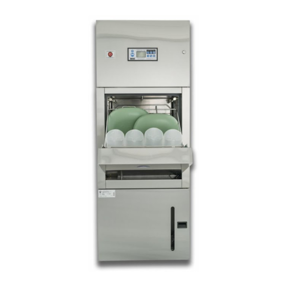
Washer Disinfector Sanitizer
Operation, Maintenance and Installation Manual
Serial Number: .....................................................
Date Installed: ......................................................
Note: Due to Malmet's Policy of continuous product improvement;
design and technical specifications are subject to change without notice.
ISSUE 5
Malmet (Australia) Pty Ltd
Head Office & Customer Service
9-11 McKay Avenue
LEETON NSW 2705
Phone: (02) 6953 7677
Email: inquiries@malmet-aus.com.au
WDS
PO Box 373
Supplied to: .....................................................
Installed by: .....................................................
1
Page
ABN 95 001 717 791
15/03/2016
Advertisement
Table of Contents

Summary of Contents for Malmet WDS
- Page 1 Operation, Maintenance and Installation Manual Serial Number: ............. Supplied to: ............. Date Installed: ............Installed by: ............. Note: Due to Malmet’s Policy of continuous product improvement; design and technical specifications are subject to change without notice. Page ISSUE 5 15/03/2016...
-
Page 2: Table Of Contents
Operation, Maintenance and Installation Manual Table of Contents Forward ........................Certifications and ..................Compliances Quality Policy ......................Safety Instructions ......................1.0 Design Parameters ....................1.1 Operating cycles 1.2 Detergent 1.3 Device Features 1.4 LCD Display Features 1.4 Operating Features 2.0 Installation and commissioning ................2.1 Installation 2.2 Service Connection and layout details 2.3 Plumbing... -
Page 3: Certifications And Compliances
Operation, Maintenance and Installation Manual Forward In order to obtain maximum life and efficiency from your Malmet WDS and to aid in the safe operation of the device, please read and understand this manual thoroughly and follow all instructions before operating the unit. -
Page 4: Safety Instructions
Operation, Maintenance and Installation Manual SAFETY INSTRUCTIONS WARNINGS Be aware of 240V / 415V Voltage. Disconnect power when servicing. Mains power ISO switch must be in an accessible position so devise can be isolated from mains power during service. Be aware of steam discharge Utensils and racks are hot to handle. -
Page 5: Design Parameters
Operation, Maintenance and Installation Manual 1.0 DESIGN PARAMETERS The WDS has been designed within the following parameters OPERATING CYCLES Three available operating (cleaning, disinfection and sanitizing) Urine / Bedpan Load: capacity: 2 x Small slipper pans, 2 x Large slipper pans, 2 x Standard bed pans and 4 x Standard... -
Page 6: Detergent
Operation, Maintenance and Installation Manual 1. 2 DETERGENT The 5 litre detergent container is accessed by opening the bottom door. Only use Malmet approved detergent (See technical data for detergent details) Pull handle on detergent door and open. Unscrew cap and pull out with suction hose (let hose hang on detergent chamber.) Remove empty bottle and replace with full bottle. -
Page 7: Device Features
Operation, Maintenance and Installation Manual DEVICE FEATURES Control panel with LCD display USB port Emergency cycle stop Wash Chamber Bowl / Utensil rack hinged Bed pan rack hinged Urine bottle rack Door Auto open and close Detergent access door CONTROL LCD DISPLAY FEATURES Page ISSUE 5 15/03/2016... -
Page 8: Operating Features
Operation, Maintenance and Installation Manual OPERATING FEATURES: POWER: On/Off Standby HANDS FREE SENSOR: For hands free opening and closing door. To operate, place hand in front of sensor. URINE ONLY: Select for Urine bottle only cycle BOWL / UTENSILS : Select for Bowls / Kidney dishes etc URINE / BEDPAN : Select for Urine bottles / Bedpans DOOR:... -
Page 9: Installation And Commissioning
WDS. If an existing soil line can be utilised this will represent a cost saving. The WDS is supplied with either an ‘S’ or ‘P’ Trap as nominated by the Purchaser. The ‘S’ Trap connects through •... - Page 10 MODEL HOT WATER COLD WATER SOIL LINE 240V 100mm ‘S’ or ‘P ’Trap Solenoid valve Solenoid valve 1 phase WDS 1ph Hot water discharge GB¾ Male GB¾ Male 20 amps 50 75-80° C hertz 415V 100mm ‘S’ or ‘P ’Trap...
-
Page 11: Service Connection And Layout Details
Operation, Maintenance and Installation Manual SERVICE CONNECTION AND LAYOUT DETAILS Page ISSUE 5 15/03/2016... -
Page 12: Plumbing
Operation, Maintenance and Installation Manual PLUMBING These Installation Guidelines must be followed to ensure the unit will operated as intended. Installations must be carried out by a qualified and licensed tradesperson. Service Connections NOTE: Plumbing connection must comply to AS3500 and Watermark Certified. Waste connection •... -
Page 13: Electrical
Operation, Maintenance and Installation Manual ELECTRICAL These Installation Guidelines must be followed to ensure the unit will operated as intended. Installations and service must be carried out by a qualified electrical licensed tradesperson. Model: WDS 1ph 240V 50Hz 1 ph 20Amp WDS 3ph... -
Page 14: Unit Loading And Operation
Operation, Maintenance and Installation Manual 3.0 UNIT LOADING AND OPERATION Refer to laminated WDS Instructions URINE BOTTLE / BEDPAN LOADING AND OPERATING CYCLE LOADING To open door, use or press Place racks into the correct positions Check that bowl Lift bedpan rack up and lock rack is in the up into position. - Page 15 Operation, Maintenance and Installation Manual 3.1.1 URINE BOTTLE / BEDPAN LOADING AND OPERATING CYCLE Refer to laminated WDS Instructions OPERATING CYCLE Open door, use or press Select URINE / BEDPAN cycle press Close door, use or press When door closes the cycle will start automatically.
-
Page 16: Urine Bottle Only Loading And Operating Cycle
Operation, Maintenance and Installation Manual URINE BOTTLE ONLY LOADING AND OPERATING CYCLE Refer to laminated WDS Instructions LOADING Open door, use or press Place racks into correct positions Bedpan rack can be in the Check that the bowl rack is in the... - Page 17 Operation, Maintenance and Installation Manual 3.2.1 URINE BOTTLE ONLY LOADING AND OPERATING CYCLE Refer to laminated WDS Instructions Operating cycle Open door, use or press Select URINE / BEDPAN cycle press Close door, use or press When door closes the cycle will start automatically.
-
Page 18: Bowl And Utensil Loading And Operating Cycle
Operation, Maintenance and Installation Manual BOWL / UTENSIL LOADING AND OPERATING CYCLE Refer to laminated WDS Instructions LOADING Open door, use or press Place racks into the correct positions Place bedpan rack Place the bowl into the down rack in the down position. - Page 19 Operation, Maintenance and Installation Manual 3.3.1 BOWL / UTENSIL LOADING AND OPERATING CYCLE Refer to laminated WDS Instructions OPERATING Open door, use or press Select Bowl / Utensil cycle, press Close door by using or press When door closes the cycle will start automatically.
-
Page 20: Cycle Of Operation
Operation, Maintenance and Installation Manual 4.0 CYCLE OF OPERATION 1. Press POWER ON BUTTON Display shows POWER POWER After short delay display shows alternating OPEN DOOR OPEN DOOR 2. OPEN DOOR: Display shows OPENING OPENING 3. WHEN DOOR IS OPEN: Display shows LOAD LOAD-ITEMS... - Page 21 Operation, Maintenance and Installation Manual 4 AFTER SELECT CYCLE: BEDPAN/URINE BOTTLE URINE ONLY OR BOWL Display shows CLOSE CLOSE-DOOR CLOSE-DOOR DOOR 5 WHEN DOOR IS CLOSING Display shows CLOSING CLOSING CLOSING 6. WHEN DOOR CLOSES UNIT STARTS OPERATING CYCLE 1: COLD FLUSH Display shows COLD-FILL 1 COLD...
- Page 22 Operation, Maintenance and Installation Manual CYCLE 3: HOT WASH PLUS DETERGENT CYCLE 2: HOT WASH PLUS DETERGENT Display shows HOT+DET HOT+DET HOT+DET-FILL 2 HOT+DET-FILL 3 FILL 3 FILL 2 When filled to correct level then shows HEATING HEATING HEATING-WATER 2 HEATING- WATER WATER 3...
- Page 23 Operation, Maintenance and Installation Manual 7. DISINFECTION / SANITIZING Display shows TEMP 50° c TEMP 50° to 93° c TEMP 50° c Steam heating chamber to 93° c When chamber reaches 93° c Disinfection for 1 min @ 93° c TEMP 93°...
-
Page 24: Detergent Warnings
Operation, Maintenance and Installation Manual TO CLOSE DOOR WITHOUT RUNNING CYCLE After the door is opened display shows LOAD ITEMS Then SELECT CYCLE Manually press DOOR BUTTON • Software will check that racks are in correct position before door closes. If racks have been moved, wrong rack will •... -
Page 25: Fault Indication
Operation, Maintenance and Installation Manual Second Warning When no full segments are showing EMPTY DETERGENT is flashing At this stage there is approximately 750mL to 1lt in bottle Third warning Fault 302 Detergent time out. No detergent in bottle When full bottle is installed the detergent line will require purging (refer to page 31) FAULT 302 FAULT 302 FAULT INDICATION... -
Page 26: Maintenance
Maintenance, preventative or breakdown, is to be completed by a qualified person. Failure to comply with this may result in unsafe conditions. The Malmet WDS is self-cleaning, however, proper care should be taken to ensure that the unit is cleaned and maintained. In accordance with maintenance instructions for Malmet WDS, regulatory and common sense practices. -
Page 27: Recommended Preventative Maintenance Schedule
Replace battery on processor PCB every 12 months. Check time and date, adjust if required. Malmet will make available on request circuit diagrams, component parts lists, descriptions, calibration instructions, or information which will assist the user’s appropriately qualified technical personnel to repair those parts of the product. -
Page 28: Fault Codes
Operation, Maintenance and Installation Manual FAULT CODES The device is controlled by a sophisticated micro-processor. The processor has fault detection capability and indicates faults by code on the LCD display as well as an audible buzzer. Software V3.03 FAULT STATE DESCRIPTION POSSIBLE CAUSES CODE... - Page 29 Operation, Maintenance and Installation Manual Incorrect spray nozzles fitted Cold Wash Run Door Open Door opened during wash cycle, faulty door interlock switch J11 J10 Cold Wash Run Pump run without solenoid Check Cycle Times parameters, Faulty solenoids Cold Wash Run Timeout before Level reached Low pump water flow, blocked spray nozzles, Faulty solenoid, Panel lockout...
- Page 30 Operation, Maintenance and Installation Manual Steam Heatup Steam Water Level Timeout Water Leakage, Steam fill solenoid failed, Steam Level Sensor Failed, Blocked inlet hose Steam Heatup Steam Water Low Level during Water Leakage, Steam fill solenoid failed, heatup Steam Level Sensor Failed, Blocked inlet hose Steam Heatup Steam Water Temperature High...
-
Page 31: Purge Reset
Operation, Maintenance and Installation Manual Purging must only be undertaken by Malmet service personal of Malmet trained facility maintenance personal. PURGE RESET Turn power OFF at control LCD display Turn power ON at control LCD display Hold down both SCROLL and SELECT buttons, when MENU is displayed, release buttons. - Page 32 Operation, Maintenance and Installation Manual DETERGENT LEVEL AND LOAD CELL CALIBRATION INSERT empty detergent bottle and also suction hose. Also make sure that the bottle is centrally located over the sensor plate. Check that the supporting plate is correctly located and is not obstructed by the detergent hose and can pivot freely.
-
Page 33: Device Service Component Identification And Part Listing
Operation, Maintenance and Installation Manual DEVICE SERVICE COMPONENT IDENTIFICATION AND PART LISTING L/H SIDE VIEW R/H SIDE VIEW REAR VIEW FRONT VIEW Page ISSUE 5 15/03/2016... - Page 34 Operation, Maintenance and Installation Manual ELECTRICAL 1 PH COMPONENTS 3 PH COMPONENTS TOP VIEW SPRAY LOCATIONS Page ISSUE 5 15/03/2016...
- Page 35 Door bottom switch J11 assy 92-4080 Water tank baffle assy 92-4043 Pump drain line assy 92-4045 Water tank screen assy 92-4042 WDS Pump assy 92-4044 Steam condenser coil 92-2092 USB adaptor socket 92-3124 Temp probe holder assy 92-4021 Spray line cool down assy...
-
Page 36: User Menu And Test Mode
Operation, Maintenance and Installation Manual USER MENU AND TEST MODE After normal Power On mode (not restart attempt), the operator can place the system into the MENU and test mode. To Enter the MENU model, press ENTER and simultaneously press SCROLL and hold for 5 seconds. The display will show “MENU”... - Page 37 Operation, Maintenance and Installation Manual LEVEL 0 LEVEL 1 SELECT COMMENTS TIME CURRENT hh:mm Displays curr Time Only HOUR hh(Increment 0..23) MINS mm(Increments 0..59) SAVE EXIT (Press Enter Toggles ON/OFF) TEST RELAYS OPEN ON/OF Door Open CLOS ON/OF Door Close COLD ON/OF Cold Tank Fill HOT ON/OF...
- Page 38 Operation, Maintenance and Installation Manual LEVEL 0 LEVEL 1 SELECT COMMENTS BP-UR Select Cycle Mode 0 URINE Select Cycle Mode 1 BOWL Select Cycle Mode 2 220: Cold Fill 1 CFLUSH 240: Cold Flush 260: Cold Fill 2 CWASH 280: Cold Wash HFD1 300: Hot Fill + Detergent HWASH...
-
Page 39: Technical Data
POWER AND WATER CONSUMPTION DATA MODEL Sanitizing Avg Cycles Avg Cycle Avg kWh CW Avg Lt HW Avg Lt per WDS 1 ph Time/ Temp per/Hr min/sec Per cycle cycle Cycle Bed pan / Urine 1 min @ 90° c 15.15... -
Page 40: Device Specifications
DEVICE SPECIFICATIONS Electrical Rating Volts 240V APPROVALS Phase / Hz 1 ph / 50 Hz Model WDS 1PH Amps 20 Amps Heater power supply pcb 1 pole 20A 240Vac Internal circuit breakers 1 ph Control power supply pcb 1 pole 10A 240Vac Steam Generator 4500W 240V 3x6.25A Star... - Page 41 750W 240V 1ph 4.6A Wash pump Horizontal multistage 116.7L/Mins s/s impeller and housing Detergent Concentrate ARTGC Class 1 Detergent Malmet specific (5Lt) Caustic Alkaline Self priming peristaltic Detergent pump 72 rpm 240V 50Hz Chemical feed pump PLUMBING Type ‘S’ or ‘P’ Trap (6mm PE) 80°...
-
Page 42: Wiring Diagram 1Ph
Operation, Maintenance and Installation Manual WIRING DIAGRAM 1PH Page ISSUE 5 15/03/2016... -
Page 43: Wiring Diagram 3 Ph
Operation, Maintenance and Installation Manual WIRING DIAGRAM 3 PH Page ISSUE 5 15/03/2016... -
Page 44: Data Logging
The D13447PC.ini file allows store of site specific data (Company Name and Site Location) which is linked to the serial number saved in the WDS unit. This is then used to generate the header information at beginning of the printed reports. - Page 45 The table is initially blank 6.5.4 Setup Pressing Setup button displays the Setup table as below: Numerous sites can be setup in the system. These sites are linked to a particular WDS machine by the site reference number. Page ISSUE 5 15/03/2016...
- Page 46 Operation, Maintenance and Installation Manual This information is printed on the Report Headers. To enter a new record, just start typing the data on the next new line. Press Save when completed. The Reference / Serial Number needs to match the Serial Number of the respective machine. This can be viewed on the machine using Diagnostics Command ’36 <Enter>’...
- Page 47 Operation, Maintenance and Installation Manual 6.5.8 How to Save Statistics The Statistics button analyses the current log data and produces a summary file eg: Report Date/Time: 23/02/2012 14:58:45 Site Reference: 12345678 Company Name: Leeton District Hospital Company Location: Palm Ave East, Leeton, NSW 2705 Report Start: 28/08/2000 13:50:30 Report End:...
- Page 48 Operation, Maintenance and Installation Manual Report Start: 25/11/2000 13:00:21 Report End: 29/05/2012 15:43:35 Total Number of wash process Starts: Mode=0 wash process starts: Mode=1 wash process starts: Mode=2 wash process starts: Total Number Completed – Success: Total Number Completed – Failed: Total Number Completed –...
- Page 49 Operation, Maintenance and Installation Manual 6.5.12 Clearing the System Log Data and Reset Cycle Counter The log data stored in the system FLASH memory can be cleared by connecting a PC with the USB port and setting the system to diagnostics mode. To clear only the log data –...
- Page 50 Website: www.malmet.com.au Warranty Statement Subject to the following conditions, we provide, from the date of purchase, the following warranty on Malmet units and spare parts: Functional components found within the unit to be defective in workmanship or material will be repaired or replaced •...
- Page 51 HOW TO MAKE A CLAIM UNDER THIS WARRANTY If you believe there is a defect in a unit you have purchased from Malmet, you must notify Malmet in writing of such defect, by sending a letter (“Notice of Defect”) to Malmet at PO Box 373, Leeton NSW 2705 prior to the expiration of the applicable warranty period set out in this warranty.
- Page 52 Please attach your proof of purchase. Your receipt/invoice is your warranty and will be required to validate any warranty. E.&O.E. In the interest of continued product improvement, Malmet (Australia) Pty Ltd reserves the right to alter specifications without notice. AUSTRALIAN CONSUMER LAW DISLAIMER: Our goods come with guarantees that cannot be excluded under the Australian Consumer Law.
- Page 53 Operation, Maintenance and Installation Manual Manufactured by Malmet (Australia) ABN 95 001 717 791 www.malmet.com.au Part No. 92-2226 Page ISSUE 5 15/03/2016...
Need help?
Do you have a question about the WDS and is the answer not in the manual?
Questions and answers