Table of Contents
Advertisement
Advertisement
Table of Contents

Related Manuals for D-Link DSG-1100-10/ME


Summary of Contents for D-Link DSG-1100-10/ME
-
Page 2: Table Of Contents
D-Link DGS-1100-10/ME User Manual Table of Contents Table of Contents ............................. i About This Guide ............................. 1 Terms/Usage ..............................1 Copyright and Trademarks ..........................1 Product Introduction ........................... 2 DGS-1100-10/ME ............................2 Front Panel ..............................2 Rear Panel ..............................2 Hardware Installation .......................... - Page 3 System > PPPoE Circuit ID Insertion Settings ..................28 System > Web Settings ..........................28 System > Telnet Settings ......................... 29 System > D-Link Discover Protocol Settings .................... 29 System > Ping Test ..........................29 System >Trace Route ..........................30 System >...
- Page 4 D-Link DGS-1100-10/ME User Manual RMON > RMON Basic Settings........................ 54 RMON > RMON Ethernet Statistics Configuration ................... 54 RMON > RMON History Control Configuration ..................54 RMON > RMON Alarm Configuration ...................... 55 RMON > RMON Event Configuration ....................... 56 Security >...
- Page 5 Safety Certifications..........................110 Features ..............................110 L2 Features ............................110 VLAN ..............................110 QoS (Quality of Service) ......................... 110 Security ..............................111 OAM ............................... 111 Management ............................111 D-Link Green Technology ........................111 Appendix C – Rack mount Instructions ....................112...
-
Page 6: About This Guide
Reproduction in any manner whatsoever without the written permission of D-Link Corporation is strictly forbidden. Trademarks used in this text: D-Link and the D-LINK logo are trademarks of D-Link Corporation; Microsoft and Windows are registered trademarks of Microsoft Corporation. Other trademarks and trade names may be used in this document to refer to either the entities claiming the marks and names or their products. -
Page 7: Product Introduction
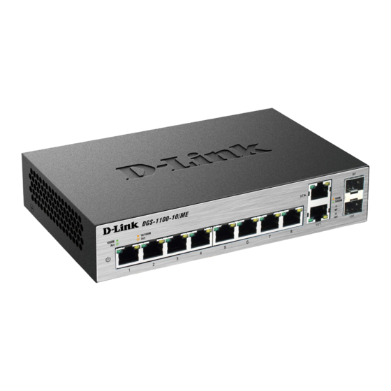
D-Link DGS-1100-10/ME User Manual Product Introduction The DGS-1100-10/ME is a member of the D-Link Metro Ethernet Switches. This Switch provides unsurpassed performance, fault tolerance, scalability, robust security, standard-based interoperability and impressive technology to future-proof departmental and enterprise network deployments. It allows IGMP Snooping and Authentication, QoS, Bandwidth Control, ACL and many security functions. It can be managed by Web UI, or commands through Telnet. -
Page 8: Hardware Installation
D-Link DGS-1100-10/ME User Manual Hardware Installation This chapter provides unpacking and installation information for the D-Link Metro Ethernet Switch. Step 1: Unpacking Open the shipping carton and carefully unpack its contents. Please consult the packing list located in the User Manual to make sure all items are present and undamaged. If any item is missing or damaged, please contact your local D-Link reseller for replacement. -
Page 9: Step 3 - Plugging In The Ac Power Cord
D-Link DGS-1100-10/ME User Manual Figure 2.2 – Wall mount installation Step 3 – Plugging in the AC Power Cord You may now connect the AC power cord into the rear of the switch and to an electrical outlet (preferably one that is grounded and surge protected). -
Page 10: Getting Started
This chapter introduces the management interface of D-Link Metro Ethernet Switch. Management Options The D-Link Metro Ethernet Switch can be managed through any port on the device by using the Web-based Management. Each switch must be assigned its own IP Address, which is used for communication with the Web-Based Management or a SNMP network manager. - Page 11 D-Link DGS-1100-10/ME User Manual Figure 3.2 –Enter the IP address 10.90.90.90 in the web browser NOTE: The switch's factory default IP address is 10.90.90.90 with a subnet mask of 255.0.0.0 and a default gateway of 0.0.0.0. When the following dialog box appears, enter your user name and password, and click OK.
-
Page 12: Configuration
Logout button first, then it will be seen as an abnormal exit and the login session will still be occupied. Click on the D-Link logo at the upper left corner of the screen to be redirected to the local D-Link website. -
Page 13: Tool Bar > Save Menu
D-Link DGS-1100-10/ME User Manual Tool Bar > Save Menu The Save Menu provides Save Configuration and Save Log functions. Figure 4.2 – Save Menu Save Configuration Select to save the entire configuration changes you have made to the device to switch’s non-volatile RAM. -
Page 14: Configuration Backup & Restore
D-Link DGS-1100-10/ME User Manual Figure 4.7 – Tool Menu > Reboot Device Configuration Backup & Restore Allow the current configuration settings to be saved to a file (not including the password), and if necessary, you can restore configuration settings from this file. Two methods can be selected: HTTP or TFTP. -
Page 15: Firmware Backup & Upgrade
The Online Help provides two ways of online support: Figure 4.11 – Online Help D-Link Support Site: This will re-direct you to the D-Link website where you can find online resources such as updated firmware images. User Guide: This can offer an immediate reference for the feature definition or configuration guide. -
Page 16: Function Tree
D-Link DGS-1100-10/ME User Manual Function Tree All configuration options on the switch are accessed through the Setup menu on the left side of the screen. Click on the setup item that you want to configure. The following sections provide more detailed description of each feature and function. -
Page 17: System > System Settings
D-Link DGS-1100-10/ME User Manual Figure4.13 – Device Information System > System Settings The System Setting allows you to configure the IP address and the basic system information of the Switch. IP Information: There are two ways for the switch to obtain an IP address: Static and DHCP (Dynamic Host Configuration Protocol). -
Page 18: System > Port Configuration > Port Settings
D-Link DGS-1100-10/ME User Manual name information in the DHCP reply packet. The TFTP server must be up and running and store the necessary configuration file in its base directory when the request is received from the Switch. Figure 4.15 – System > DHCP Auto Configuration Timeout (1-65535): Specify the timeout. -
Page 19: System > Port Configuration > Port Description
D-Link DGS-1100-10/ME User Manual Address Learning: Enable or disable the address learning function. The default setting is Enabled. System > Port Configuration > Port Description In the Port Description page, you may name various ports on the Switch. Figure 4.17 – System > Port Configuration > Port Description From Port / To Port: Specify the range of ports to describe. -
Page 20: System > Ipv6 Settings > Ipv6 Default Gateway Settings
D-Link DGS-1100-10/ME User Manual Figure 4.18 – System > IPv6 Settings > IPv6 System Settings IPv6 System Settings: Interface Name: Displays the IPv6 interface name. IPv6 State: Select to either enable or disable IPv6. DHCPv6 Client: Select to either enable or disable the switch as an IPv6 client. -
Page 21: System > Snmp Settings > Snmp Global State
D-Link DGS-1100-10/ME User Manual Link Layer MAC Address: Enter the link layer MAC address. Click Apply for the settings to take effect. Interface Name: Specifies the interface name of the IPv6 neighbor. To search for all the current interfaces on the Switch, go to the second Interface Name field in the middle part of the window, tick the All check box. -
Page 22: System > Snmp Settings > Snmp Group Table
D-Link DGS-1100-10/ME User Manual Click Apply to create a new SNMP user account or click Delete to remove any existing data. System > SNMP Settings > SNMP Group Table This page is used to maintain the SNMP Group Table associating to the users in SNMP User Table. -
Page 23: System > Snmp Settings > Snmp Community Table
D-Link DGS-1100-10/ME User Manual Subtree OID: The Object Identifier (OID) Subtree for the view. The OID identifies an object tree (MIB tree) that will be included or excluded from access by an SNMP manager. OID Mask: The mask of the Subtree OID. 1 means this object number is concerned, 0 means do not concerned. -
Page 24: System > Snmp Settings > Snmp Trap Settings
D-Link DGS-1100-10/ME User Manual System > SNMP Settings > SNMP Trap Settings From this page you can specify whether the device can send SNMP notifications. Figure 4.28 – System > SNMP Settings > SNMP Trap Settings SNMP Authentication Traps: Tick the box to send authentication failure notifications. -
Page 25: System > Arp Aging Time Settings
D-Link DGS-1100-10/ME User Manual Figure 4.30 – System > MAC Address Aging Time MAC Address Aging Time (10-600): Specifies the aging time of MAC address on the Switch. The range is from 10 to 600, and the default is 300 seconds. -
Page 26: System > Telnet Settings
Telnet protocol is 23. System > D-Link Discover Protocol Settings For the D-Link Discovery Protocol (DDP) supported device, this page is an option for you to disable DDP or configure the DDP packet report timer. Figure 4.35 – System > D-Link Discover Protocol Settings D-Link Discover Protocol State: Enable or disable the Discover Protocol state. -
Page 27: System >Trace Route
D-Link DGS-1100-10/ME User Manual Figure 4.36 – System > Ping Test The user may tick the Infinite times radio button to tell the ping program to keep sending ICMP Echo packets to the specified IP address until the program is stopped. You may opt to choose a specific number of times to ping the Target IPv4 or IPv6 Address by clicking its radio button and entering a number between 1 and 255. -
Page 28: System > System Log Configuration > System Log Settings
D-Link DGS-1100-10/ME User Manual Figure 4.38 – System > MAC Notification Settings MAC Notification Global Settings: State: Select to enable or disable MAC notification globally on the Switch. Interval (1-2147483647 sec): Enter the time in seconds between notifications. History Size (1-500): Enter the maximum number of entries listed in the history log used for notification. Up to 500 entries can be specified. -
Page 29: System > Time Profile
D-Link DGS-1100-10/ME User Manual Figure 4.40 - System > System Log Configuration > System Log Server Server ID: Select the Server ID. The field range is 1-4. Severity: Select the minimum severity from which warning messages are sent to the server. There are three levels. -
Page 30: System > Ieee802.3Az Eee Settings
D-Link DGS-1100-10/ME User Manual By reducing power consumption less heat is produced resulting in extended product life and lower operating costs. By default, Cable Length Detection and Link Status Detection are enabled. Select either Enabled or Disabled. If you select Enabled, make any changes to the settings below and click Apply. -
Page 31: Configuration > 802.1Q Vlan
D-Link DGS-1100-10/ME User Manual Figure 4.43 – System > IEEE802.3az EEE Settings From Port / To Port: A consecutive group of ports may be configured starting with the selected port. State: Enabled or Disabled the IEEE802.3az EEE for the specified ports. By default, all ports are enabled. - Page 32 D-Link DGS-1100-10/ME User Manual Figure4.45 – Configuration > 802.1Q VLAN > Add VLAN Click Apply and the 802.1Q VLAN Configuration Table will be displayed with updates. Figure 4.46 - Configuration > 802.1Q VLAN > Example VIDs Click the VID number to display the VLAN group configuration. Change the port assignment and then click Apply to implement changes made.
-
Page 33: Configuration > 802.1Q Management Vlan
D-Link DGS-1100-10/ME User Manual Configuration > 802.1Q Management VLAN The 802.1Q Management VLAN setting allows user to transfer the authority of the switch from the default VLAN to others created by users. This allows managing the whole network more flexible. -
Page 34: Configuration > Igmp Snooping > Igmp Snooping
D-Link DGS-1100-10/ME User Manual Role: Select either UNI or NNI. UNI – User-to-network interface which specifies that communication between the specified user and a specified network will occur. NNI –Network-to-network interface specifies that communication between two specified networks will occur. -
Page 35: Configuration > Igmp Snooping > Igmp Access Control Settings
D-Link DGS-1100-10/ME User Manual restarted whenever a Query control message is received over that port. If there were no Query control messages received for 'Router Port Purge Interval' time, the learned router port entry will be purged. Default is 260 seconds. -
Page 36: Configuration > Igmp Snooping > Host Table
D-Link DGS-1100-10/ME User Manual Configuration > IGMP Snooping > Host Table The Host Table page displays the information of Host Table. Including VLAN ID, Group, Port Number and Host IP. Figure 4.57 - Configuration > IGMP Snooping > Host Table Configuration >... -
Page 37: Configuration > Mld Snooping > Mld Host Table
D-Link DGS-1100-10/ME User Manual Max Response Time (10-25 sec): Specifies the time interval in seconds after which a port is removed from the Multicast membership group. Ports are removed from the Multicast membership when the port sends a Done Message, indicating the port requests to leave the Multicast group. The field range is 10-25 seconds. -
Page 38: Configuration > Jumbo Frame
D-Link DGS-1100-10/ME User Manual Figure 4.63 - Configuration > ISM VLAN Settings ISM VLAN Global State: Enable or disable the IGMP Snooping Multicast (ISM) VLAN Global State. Click the Apply button to confirm the ISM VLAN Global State. VID: Add the corresponding VLAN ID of the Multicast VLAN. You may enter a value between 2 and 4094. -
Page 39: Configuration > Port Mirroring
D-Link DGS-1100-10/ME User Manual Configuration > Port Mirroring Port Mirroring is a method of monitoring network traffic that forwards a copy of each incoming and/or outgoing packet from one port of the Switch to another port, where the packet can be studied. This enables network managers to better monitor network performances. -
Page 40: Configuration > Sntp Settings > Time Settings
D-Link DGS-1100-10/ME User Manual Recover Time (0 or 60-1000000): Time allowed (in seconds) for recovery when a Loopback is detected. The Loop Detection Recover Time can be set at 0 seconds, or 60 to 1000000 seconds. Entering 0 will disable the Loop Detection Recover Time. The default is 60 seconds. -
Page 41: Configuration > Dhcp Relay > Dhcp Relay Global Settings
D-Link DGS-1100-10/ME User Manual Figure 4.69 – Configuration > SNTP > TimeZone Settings Daylight Saving Time State: Enable or disable the DST Settings. Daylight Saving Time Offset: Use this drop-down menu to specify the amount of time that will constitute your local DST offset - 30, 60, 90, or 120 minutes. -
Page 42: Configuration > Dhcp Relay > Dhcp Relay Interface Settings
D-Link DGS-1100-10/ME User Manual (if the relay agent is configured), to the packet. Once the option 82 information has been added to the packet it is sent on to the DHCP server. When the DHCP server receives the packet, if the server is capable of option 82, it can implement policies like restricting the number of IP addresses that can be assigned to a single remote ID or circuit ID. -
Page 43: Configuration > Dhcp Local Relay Settings
D-Link DGS-1100-10/ME User Manual Figure 4.71 - Configuration > DHCP Relay > DHCP Relay Interface Settings Interface: The IP interface on the Switch that will be connected directly to the server. Server IP: Enter the IP address of the DHCP server. Up to four server IPs can be configured per IP Interface. -
Page 44: Configuration > 802.3Ah Ethernetlink Oam > Ethernet Oam Port Settings
D-Link DGS-1100-10/ME User Manual DHCPv6 Relay Hops Count Limit (1-32): The field allows and entry between 1 and 32 to define the maximum number of router hops DHCPv6 messages can be forwarded. The default hop count is 4. DHCPv6 Relay Option37 State: Specifies the DHCPv6 Relay Option37 State to be enabled or disabled. -
Page 45: Configuration > Duld > Duld Port Settings
Click Apply to implement changes made. Configuration > DULD > DULD Port Settings The Switch features a D-Link Unidirectional Link Detection (DULD) module. The unidirectional link detection provides a mechanism that can be used to detect unidirectional link for Ethernet switches whose PHYs do not support unidirectional OAM operation. -
Page 46: Configuration > Multicast Forwarding & Filter > Multicast Forwarding
D-Link DGS-1100-10/ME User Manual Admin State: Enable or disable the administration state. This indicates these ports unidirectional link detection status. The default state is Disabled. Mode: Toggle between Shutdown and Normal. When Shutdown is selected if any unidirectional link is detected, this feature will disable the port and log an event. -
Page 47: Configuration > Multicast Forwarding & Filter > Ip Multicast Profile Settings
D-Link DGS-1100-10/ME User Manual Figure4.78 - Configuration > Multicast Forwarding & Filter > Multicast Filter Mode From Port / To Port: Specify the ports of the VLAN on which the corresponding MAC address belongs to. Multicast Filtering Mode: Select an action from the drop-down menu when the Switch receives a multicast packet that is to be forwarded to one of the ports in the range specified above. -
Page 48: Configuration > Multicast Forwarding & Filter > Max Multicast Group Settings
D-Link DGS-1100-10/ME User Manual Figure 4.80 - Configuration > IGMP Snooping > Limited Multicast Range Settings From Port / To Port: Select the port ranges to be configured. Profile Type: Select IPv4 or IPv6. Profile ID: Select the Profile ID. - Page 49 D-Link DGS-1100-10/ME User Manual Figure4.82 – QoS > Traffic Control From Port/To Port: Select a range of ports to be configured. Drop Threshold (64Kbps * N): If storm control is enabled (default is disabled), the threshold is from of 64 ~ 1,024,000 Kbit per second, with steps (N) of 64Kbps.
-
Page 50: Qos > Bandwidth Control
D-Link DGS-1100-10/ME User Manual QoS > Bandwidth Control The Bandwidth Control page allows network managers to define the bandwidth settings for a specified port’s transmitting and receiving data rates. Figure 4.83 – QoS > Bandwidth Control From Port / To Port: Select a range of ports to be configured. -
Page 51: Rmon > Rmon Basic Settings
D-Link DGS-1100-10/ME User Manual Select QoS Mode: Select PortBase, 802.1p, or DSCP. Quening Mechanism: Strict Priority: Selecting this will set the highest queue to be emptied first while the other queues will follow the weighted round-robin scheduling scheme WRR: Use the weighted round-robin (WRR) algorithm to handle packets in an even distribution in priority classes of service. -
Page 52: Rmon > Rmon Alarm Configuration
D-Link DGS-1100-10/ME User Manual Figure 4.87 - RMON > RMON History Control Configuration The History Control Configuration contains the following fields: Index (1 - 65535): Enter the history control entry number. Port: Enter the port from which the RMON information was taken. -
Page 53: Rmon > Rmon Event Configuration
Click Apply for the settings to take effect. Security > Safeguard Engine D-Link’s Safeguard Engine is a robust and innovative technology that automatically throttles the impact of packet flooding into the switch's CPU. This function helps protect the Switch from being interrupted by malicious viruses or worm attacks. -
Page 54: Security > Port Security > Port Security Fdb Entry
D-Link DGS-1100-10/ME User Manual Figure 4.91 - Security > Port Security > Port Security Settings The Port Security page contains the following fields: From Port/To Port: Select a range of ports to be configured. Admin State: Select either enable or disable Port Security (locked MAC address table for the selected ports). - Page 55 D-Link DGS-1100-10/ME User Manual software and the RADIUS server. Depending on the authenticated results, the port is either made available to the user, or the user is denied access to the network. The RADIUS servers make the network a lot easier to manage for the administrator by gathering and storing the user lists.
-
Page 56: Security > 802.1X > 802.1X User
D-Link DGS-1100-10/ME User Manual If ForceUnauthorized is selected, the port will remain in the unauthorized state, ignoring all attempts by the client to authenticate. The Switch cannot provide authentication services to the client through the interface. If Auto is selected, it will enable 802.1X and cause the port to begin in the unauthorized state, allowing only EAPOL frames to be sent and received through the port. -
Page 57: Security > 802.1X > 802.1X Guest Vlan
D-Link DGS-1100-10/ME User Manual Figure 4.96 - Security > 802.1X > 802.1X Authentication RUDIUS Index: Select the desired RADIUS server to configure: 1, 2 or 3. IP Address: Select IPv4 or IPv6 and enter the IP address. Authentication Port (1 - 65535): Enter the RADIUS authentic server(s) UDP port. The default port is 1812. - Page 58 D-Link DGS-1100-10/ME User Manual Figure 4.98 - Security > MAC Address Table > Static Mac Address The Static MAC Address List table displays static MAC addresses that are connected, as well as the VID. Click Add Mac to add a new MAC address, you also need to select the assigned Port number, enter both the Mac Address and VID and Click Apply.
-
Page 59: Security > Mac Address Table > Dynamic Forwarding Table
D-Link DGS-1100-10/ME User Manual Figure 4.99 - Security > MAC Address Table > Static Mac Address-add MAC Security > MAC Address Table > Dynamic Forwarding Table This allows the Switch’s dynamic MAC address forwarding table to be viewed. When the Switch learns an association between a MAC address and a port number, it makes an entry into its forwarding table. -
Page 60: Security > Access Authentication Control > Authentication Policy Settings
D-Link DGS-1100-10/ME User Manual Security > Access Authentication Control > Authentication Policy Settings This feature will enable an administrator-defined authentication policy for users trying to access the Switch. When enabled, the device will check the Login Method List and choose a technique for user authentication upon login. -
Page 61: Security > Access Authentication Control > Authentication Server
D-Link DGS-1100-10/ME User Manual Figure 4.103 – Security > Access Authentication control > Authentication Server Group Enter a group name of no more than 15 alphanumeric characters to define the user group. After clicking Apply, the new user-defined group will be displayed in the Server Group table. Here, it can be configured as the user desires. -
Page 62: Security > Access Authentication Control > Login Method Lists
D-Link DGS-1100-10/ME User Manual RADIUS – Enter this parameter if the server host utilizes the RADIUS protocol. Authentication Port (1 - 65535): Enter a number between 1 and 65535 to define the virtual port number of the authentication protocol on a server host. The default port number is 1812 but the user may set a unique port number for higher security. -
Page 63: Security > Access Authentication Control > Local Enable Password Settings
D-Link DGS-1100-10/ME User Manual Figure 4.107 – Security > Access Authentication control > Enable Method Lists To define an Enable Login Method List, set the following parameter and click Apply: Method List Name: Enter a method list name defined by the user of up to 15 characters. -
Page 64: Monitoring > Statistics
D-Link DGS-1100-10/ME User Manual Figure 4.109 – Security > Traffic Segmentation Configure traffic segmentation by selecting a port or ports from the drop-down menu, then next to Port Map, select what ports to map to. Click Apply. Click Select All to select all port maps or click Clear to uncheck port maps. -
Page 65: Monitoring > Session Table
D-Link DGS-1100-10/ME User Manual Previous Page: Go back to the Statistics main page. Refresh: To renew the details collected and displayed. Clear Counter: To reset the details displayed. Monitoring > Session Table The Session Table allows you to view detailed information on the current configuration session of the Switch. -
Page 66: Monitoring > Port Utilization
D-Link DGS-1100-10/ME User Manual Figure 4.114 – Monitoring > Memory Utilization The information is described as follows: Time Interval: Select the desired setting between 1s and 60s, where "s" stands for seconds. The default value is one second. Record Number: Select the number of times the Switch will be polled between 20 and 200. The default value is 200. -
Page 67: Monitoring > Packet Size
D-Link DGS-1100-10/ME User Manual Record Number: Select the number of times the Switch will be polled between 20 and 200. The default value is 200. Show/Hide: Check whether to display Utilization. Clear: Click to clear all statistic counters on this window. -
Page 68: Monitoring > Packets > Transmitted (Tx)
D-Link DGS-1100-10/ME User Manual The following fields can be set or viewed: Time Interval: Select the desired setting between 1s and 60s, where “s” stands for seconds. The default value is one second. Record Number: Select the number of times the Switch will be polled between 20 and 200. The default value is 200. -
Page 69: Monitoring > Packets > Received (Rx)
D-Link DGS-1100-10/ME User Manual Figure 4.119 - Monitoring > Packet s > Transmitted (TX) (table for Bytes and Packets) The following fields can be set or viewed: Time Interval: Select the desired setting between 1s and 60s, where “s” stands for seconds. The default value is one second. - Page 70 D-Link DGS-1100-10/ME User Manual Figure 4.120 - Monitoring > Packets > Received (RX) (line graph for Bytes and Packets) To view the Received Packets Table, click the link View Table, which will show the following table: Figure 4.121 - Monitoring > Packet s > Received (RX) (table for Bytes and Packets) The following fields can be set or viewed: Time Interval: Select the desired setting between 1s and 60s, where “s”...
-
Page 71: Monitoring > Packets > Umb Cast (Rx)
D-Link DGS-1100-10/ME User Manual Show/Hide: Check whether or not to display Bytes and Packets. Clear: Click to clear all statistic counters on this window. View Table: Click to display a table rather than a line graph. View Line Chart: Click to display a line graph rather than a table. -
Page 72: Monitoring > Errors > Received (Rx)
D-Link DGS-1100-10/ME User Manual The following fields can be set or viewed: Time Interval: Select the desired setting between 1s and 60s, where “s” stands for seconds. The default value is one second. Record Number: Select the number of times the Switch will be polled between 20 and 200. The default value is 200. -
Page 73: Monitoring > Errors > Transmitted (Tx)
D-Link DGS-1100-10/ME User Manual Figure 4.125 - Monitoring > Errors > Received (RX) (table) The following fields can be set or viewed: Time Interval: Select the desired setting between 1s and 60s, where “s” stands for seconds. The default value is one second. - Page 74 D-Link DGS-1100-10/ME User Manual Figure 4.126 - Monitoring > Errors > Transmitted (TX) (line graph) To view the Transmitted Error Packets Table, click the link View Table, which will show the following table: Figure 4.127 - Monitoring > Errors > Transmitted (TX) (table) The following fields can be set or viewed: Time Interval: Select the desired setting between 1s and 60s, where “s”...
-
Page 75: Monitoring > Cable Diagnostics
D-Link DGS-1100-10/ME User Manual LateColl: Counts the number of times that a collision is detected later than 512 bit-times into the transmission of a packet. ExColl: Excessive Collisions. The number of packets for which transmission failed due to excessive collisions. -
Page 76: Monitoring > Browse Arp Table
D-Link DGS-1100-10/ME User Manual Figure 4.129 - Monitoring > System Log ID: Displays an incremented counter of the System Log entry. The Maximum entries are 500. Time: Displays the time in days, hours, and minutes the log was entered. Log Description: Displays the description of event recorded. -
Page 77: Monitoring > Ethernet Oam > Browse Ethernet Oam Statistics
D-Link DGS-1100-10/ME User Manual Figure 4.131 - Monitoring > Ethernet OAM > Browse Ethernet OAM Event Log Select a Port and click Find to display the Ethernet OAM event log information. Enter a Port or check All Ports then click Clear to remove Ethernet OAM event log information. - Page 78 D-Link DGS-1100-10/ME User Manual Figure 4.133 - Monitoring > Port Access Control > RADIUS Authentication You may also select the desired time interval to update the statistics, between 1s and 60s, where “s” stands for seconds. The default value is one second. To clear the current statistics shown, click the Clear button in the top left corner.
-
Page 79: Monitoring > Port Access Control > Radius Account Client
D-Link DGS-1100-10/ME User Manual Monitoring > Port Access Control > RADIUS Account Client This RADIUS Account Client page shows managed objects used for managing RADIUS accounting clients, and the current statistics associated with them. It displays one row for each RADIUS authentication server that the client shares a secret with. -
Page 80: Lldp > Basic Lldp Port Settings
D-Link DGS-1100-10/ME User Manual keep the information in the Management Information Base (MIB). SNMP utilities can learn the network topology by obtaining the MIB information in each LLDP device. The LLDP function is enabled by default. Figure 4.135 – LLDP > LLDP Global Settings LLDP: When this function is Enabled, the switch can start to transmit, receive and process the LLDP packets. -
Page 81: Lldp > 802.1 Extension Lldp Port Settings
D-Link DGS-1100-10/ME User Manual Port Description: Specifies whether the Port Description TLV is enabled on the port. The possible field values are: Enabled – Enables the Port Description TLV on the port. Disabled – Disables the Port Description TLV on the port. -
Page 82: Lldp > Lldp Management Address Settings
D-Link DGS-1100-10/ME User Manual Figure4.138 – LLDP > 802.3 Extension LLDP Port Settings From Port/To Port: Select a range of ports to be configured. MAC/PHY Configuration/Status: Select either Enabled or Disabled. Maximum Frame Size: Select either Enabled or Disabled. Once configured click Apply to implement changes made and click Refresh to refresh the table information. -
Page 83: Lldp > Lldp Management Address Table
D-Link DGS-1100-10/ME User Manual Figure 4.140 – LLDP > LLDP Statistics Table The following information can be viewed: LLDP Statistics System: Displays the counters that refer to the whole switch. Last Change Time – Displays the time for when the last change entry was last deleted or added. It is also displays the time elapsed since last change was detected. -
Page 84: Lldp > Lldp Local Port Table
D-Link DGS-1100-10/ME User Manual IF Type: Displays the IF Type. OID: Displays the SNMP OID. Advertising Ports: Displays the advertising ports. LLDP > LLDP Local Port Table The LLDP Local Port Table page displays LLDP local port information. Figure 4.142 –LLDP > LLDP Local Port Table Port : Displays the port number. -
Page 85: Lldp > Lldp Remote Port Table
D-Link DGS-1100-10/ME User Manual LLDP > LLDP Remote Port Table This LLDP Remote Port Table page is used to display the LLDP Remote Port Brief Table. Select the port number and click Search to display additional information. Figure 4.145 – LLDP > LLDP Remote Port Table To view the settings for a remote port, click View Normal and the following page is displayed. -
Page 86: Appendix A - Ethernet Technology
D-Link DGS-1100-10/ME User Manual Appendix A - Ethernet Technology This chapter will describe the features of the D-Link DGS-1100-10/ME and provide some background information about Ethernet/Fast Ethernet/Gigabit Ethernet switching technology. Gigabit Ethernet Technology Gigabit Ethernet is an extension of IEEE 802.3 Ethernet utilizing the same packet structure, format, and support for CSMA/CD protocol, full duplex, and management objects, but with a tenfold increase in theoretical throughput of over 100-Mbps Fast Ethernet and a hundredfold increase over 10-Mbps Ethernet. -
Page 87: Appendix B - Technical Specifications
D-Link DGS-1100-10/ME User Manual Appendix B - Technical Specifications Physical & Environment Hardware Specifications input, 100~240 VAC, 50/60Hz, Key Components / Performance internal universal power supply Switching Capacity: 20Gbps Acoustic Value: 0dB (Fan-less) Max. Forwarding Rate: 14.88Mpps Operation Temperature -5~50°C Forwarding Mode: Store and Forward Storage Temperature -40~70°C... -
Page 88: Security
D-Link DGS-1100-10/ME User Manual - DSCP - Power Saving by LED Shut-Off: Posered LEDs can be turned on/off by port or system Supports Strict / WRR mode in queue through schedule. handling Support Port based bandwidth control - Power Saving by Port Shut-Off: Each port on the system can be turned on/off by schedule. -
Page 89: Appendix C – Rack Mount Instructions
D-Link DGS-1100-10/ME User Manual Appendix C – Rack mount Instructions Safety Instructions - Rack Mount Instructions - The following or similar rack-mount instructions are included with the installation instructions: A) Elevated Operating Ambient - If installed in a closed or multi-unit rack assembly, the operating ambient temperature of the rack environment may be greater than room ambient.
Need help?
Do you have a question about the DSG-1100-10/ME and is the answer not in the manual?
Questions and answers