
Subscribe to Our Youtube Channel
Related Manuals for Arbor Technology EPIC-747E


Summary of Contents for Arbor Technology EPIC-747E
- Page 1 EPIC-747E Wide Range Temperature EPIC Compact Board User’s Manual Version 1.0 2012.09...
- Page 2 This page is intentionally left blank.
-
Page 3: Table Of Contents
Index Contents Chapter 1 - Introduction ..........1 1.1 Copyright Notice ............2 1.2 Declaration of Conformity..........2 1.3 About this User’s Manual ...........3 1.4 Warning ...............3 1.5 Replacing the Lithium Battery ........4 1.6 Technical Support ............4 1.7 Warranty ..............4 1.8 Packing List..............5 1.9 Ordering Information ..........5 1.10 Specifications ............6 1.11 Board Dimensions ............7... - Page 4 Index USB3~4: USB Connectors ........31 DIO1: Digital IO Connector ........32 JFRT1: Switched and Indicators ......33 MINIPCI1: Mini PCI slot ..........34 MC1: Mini-Card Slot ..........35 JBATT1: External Battery Connector ....36 SIM1: SIM card Socket ...........37 SATA1: Serial ATA Connectors ......38 12VIN1: +12V Connector ........39 SAPO1: Small 4P Power Connector .....40 2.3 The Installation Paths of CD Driver......41 Chapter 3 - BIOS ............
-
Page 5: Chapter 1 Introduction
Introduction Chapter 1 Introduction Chapter 1 - Introduction - 1 -... -
Page 6: Copyright Notice
Introduction 1.1 Copyright Notice All Rights Reserved. The information in this document is subject to change without prior notice in order to improve the reliability, design and function. It does not represent a commitment on the part of the manufacturer. Under no circumstances will the manufacturer be liable for any direct, indirect, special, incidental, or consequential damages arising from the use or inability to use the product or documentation, even if advised of the possibility of such... -
Page 7: About This User's Manual
Introduction RoHS ARBOR Technology Corp. certifies that all components in its products are in compliance and conform to the European Union’s Restriction of Use of Hazardous Substances in Electrical and Electronic Equipment (RoHS) Directive 2002/95/EC. The above mentioned directive was published on 2/13/2003. The main... -
Page 8: Replacing The Lithium Battery
Introduction 1.5 Replacing the Lithium Battery Incorrect replacement of the lithium battery may lead to a risk of explosion. The lithium battery must be replaced with an identical battery or a battery type recommended by the manufacturer. Do not throw lithium batteries into the trash-can. It must be disposed of in accordance with local regulations concerning special waste. -
Page 9: Packing List
Packing List Before you begin installing your single board, please make sure that the following materials have been shipped: 1 x EPIC-747E EPIC Compact Board with heat sink 1 x Power cable 1 x Driver CD 1 x Quick Installation Guide If any of the above items is damaged or missing, contact your vendor im- mediately. -
Page 10: Specifications
Introduction 1.10 Specifications Form Factor EPIC Compact Board Soldered onboard Intel Atom N455 1.6GHz processor ® Chipset Intel ICH8M ® System Memory Soldered onboard DDR3 2GB SDRAM Integrated Intel Graphics Media Accelerator 3150, ® Display Analog RGB/ Single Channel 18-bit LVDS/ Dual Independent Display 2 x Realtek RTL8111E PCIe Gigabit Ethernet Ethernet... -
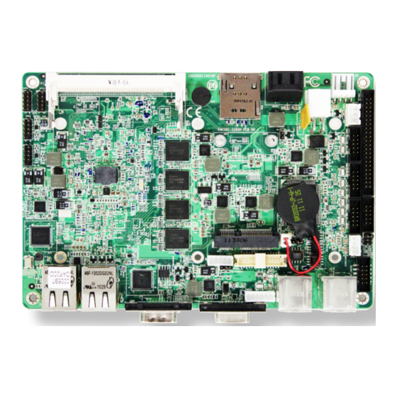
Page 11: Board Dimensions
Introduction 1.11 Board Dimensions Top View - 7 -... - Page 12 Introduction This page is intentionally left blank. - 8 -...
-
Page 13: Chapter 2 Installation
Installation Chapter 2 Installation Chapter 2 - Installation - 9 -... -
Page 14: Block Diagram
Installation 2.1 Block Diagram Analog R.G.B. Intel® Atom Single Channel DDR3 Soldered on board N455 1.6GHz DDR3 2GB SDRAM 667MHz Single Channel 18-bit LVDS LVDS DF13-30 DMIx4 COM1~ COM5 COM1 ~ COM5 COM1,3,5: RS-232 8 x USB ports USB I/F COM2: RS-232/422/485 port selectable AUDIO HD Link... -
Page 15: Jumpers And Connectors
Installation 2.2 Jumpers and Connectors Jumpers JRS1 JBAT1 JAT1 4 JVLCD1 - 11 -... - Page 16 Installation Connectors COM2 IDE1 AUDIO1 EATX1 JCOM1 SAPO1 COM3 COM4 COM5 USB2 12VIN1 USB1 SATA1 EKBMS1 SIM1 VGA1 JBATT1 LVDS1 COM1 INV1 MPCI1 26 LAN2 LAN1 JFRT1 25 DIO1 USB3 USB4 - 12 -...
-
Page 17: Jumpers
Installation Jumpers JRS1: COM2 RS-232/422/485 Mode Selection (1) The onboard COM2 port can be configured to operate in RS-232, RS-422 or RS-485 modes. RS-422 modes differ in the way RX/TX is being handled. Jumper JRS1 switches between RS-232 or RS-422/485 mode. Connector type: 2.00mm pitch 2x3-pin headers. -
Page 18: Jbat1: Clear Cmos Setting
Installation JBAT1: Clear CMOS Setting (2) If the board refuses to boot due to inappropriate CMOS settings here is how to proceed to clear (reset) the CMOS to its default values. Connector type: 2.00mm pitch 1x3-pin headers Mode Keep CMOS (Default) Clear CMOS You may need to clear the CMOS if your system cannot boot up because you forgot your password, the CPU clock setup is incorrect, or the CMOS settings... - Page 19 Installation - 15 -...
-
Page 20: Jvlcd1: Lcd Panel Voltage Selection
Installation JVLCD1: LCD Panel Voltage Selection (3) The voltage of LCD panel could be selected by JVLCD1 in +5V or +3.3V. Connector type: 2.00 mm pitch 1x3-pin headers Voltage +3.3V (Default) - 16 -... -
Page 21: Jat1: At/Atx Power Mode Selection
Installation JAT1: AT/ATX Power Mode Selection (4) The power mode jumper selects the power mode for the system. Connector type: 2.00mm pitch 1x2-pin headers. Mode Short AT Mode Open ATX Mode (Default) Note: 1. To activate the ATX power mode, you must turn on the power button switch first (the connector for power button swtich is located in JFRT1). -
Page 22: Connectors
Installation Connectors IDE1: IDE Connector (5) An IDE drive ribbon cable has two connectors to support two IDE devices. If a ribbon cable connects to two IDE drives at the same time, one of them has to be configured as Master and the other has to be configured as Slave by setting the drive select jumpers on the drive. - Page 23 Installation 43 44 - 19 -...
- Page 24 Installation EATX1: ATX Feature Connector (6) Connector type: 2.54mm pitch 1x3-pin box wafer connector Description PS-ON 5V_SB - 20 -...
-
Page 25: Com2~5: Serial Port Connectors
Installation COM2~5: Serial Port Connectors (7, 8, 9, 10) Connector type: 2.00mm pitch 2x5-pin box headers. Description Description DCD# DTR# DSR# RTS# CTS# 9 10 COM3 COM4 COM5 COM2 - 21 -... -
Page 26: Audio1: Audio Connector
Installation AUDIO1: AUDIO Connector (11) Connect a tape player or another audio source to the light blue Line-in connector to record audio on your computer or to play audio through your computer’s sound chip and speakers. Connect a micro-phone to the pink microphone connector to record audio to your computer. -
Page 27: Jcom1: Rs-422/485 Output Connector
Installation JCOM1: RS-422/ 485 Output Connector (12) Connector type: 2.00mm pitch 1x4 box wafer connector RS-422 RS-485 Data+ Data- - 23 -... -
Page 28: Usb1~2: Usb Connectors
Installation USB1~2: USB Connectors (13, 14) The USB connector supports two USB 2.0 ports w/ 480Mb/s. Connector type: double stack USB type A. 1 2 3 4 1 2 3 4 USB1 USB2 - 24 -... -
Page 29: Ekbms1: Keyboard & Mouse Connector
Installation EKBMS1: Keyboard & Mouse Connector (15) Connector Type: 2.0mm pitch 1x6-pin box wafer connector Description KB_DATA MS_DATA KB_CLK KB_VCC MS_CLK EKBMS1 - 25 -... -
Page 30: Vga1: Analog Rgb Connector
Installation VGA1: Analog RGB Connector (16) Connector type: D-Sub 15-pin female. Description Description GREEN BLUE D-DATA H-SYNC V-SYNC D-DCLK VGA1 - 26 -... -
Page 31: Lvds1: Lvds Lcd Connector
Installation LVDS1: LVDS LCD Connector (17) The LVDS connector supports 18-bit single channel LVDS. VDD could be selected by JVLCD1 in +5V or +3.3V. Connector type: DF-13-30DP-1.25V Description Description TX1CLK+ TX1CLK- TX1D0+ TX1D0- TX1D1+ TX1D1- TX1D2+ TX1D2- - 27 -... -
Page 32: Com1: Serial Port Connector
Installation COM1: Serial Port Connector (18) Connector type: D-Sub 9-pin male. Description Description DCD# DSR# RTS# CTS# DTR# COM1 - 28 -... -
Page 33: Inv1: Lcd Inverter Connector
Installation INV1: LCD Inverter Connector (19) Connector type: 2.00mm pitch 1x5-pin box wafer connector. Description +12V Backlight on/off Brightness control - 29 -... -
Page 34: Lan1~2: Gigabit Ethernet Connectors
Installation LAN1~2: Gigabit Ethernet Connectors (20, 21) Connector type: RJ-45 LAN1 LAN2 - 30 -... -
Page 35: Usb3~4: Usb Connectors
Installation USB3~4: USB Connectors (22, 23) Connector type: 2.00 mm pitch 2x5-pin headers. Description Description USBD- USBD- USBD+ USBD+ N/C (Key) USB3 USB4 - 31 -... -
Page 36: Dio1: Digital Io Connector
Installation DIO1: Digital I/O Connector (24) DIO1 is a 8-bit DIO connector that supports 8-bit programmable digital input and output. Connector type: 2.00 mm pitch 2x5-pin headers. Description Description DIO0 DIO1 DIO2 DIO3 DIO4 DIO5 DIO6 DIO7 - 32 -... -
Page 37: Jfrt1: Switched And Indicators
Installation JFRT1: Switches and Indicators (25) It provides connectors for system indicators that provides light indication of the computer activities and switches to change the computer status. Connector type: 2.00 mm pitch 2x5-pin headers Description Description RESET+ RESET- Power LED+ Power LED- HDD LED+ HDD LED-... -
Page 38: Minipci1: Mini Pci Slot
Installation MINIPCI1: Mini PCI slot (26) - 34 -... -
Page 39: Mc1: Mini-Card Slot
Installation MC1: Mini-Card Slot (27) - 35 -... -
Page 40: Jbatt1: External Battery Connector
Installation JBATT1: External Battery Connector (28) Connector type: 2.00 mm pitch 1x2-pin box headers. Description +3.3V - 36 -... -
Page 41: Sim1: Sim Card Socket
Installation SIM1: SIM card Socket (29) Connector type: Foxconn WL618E2-U05-7F CX1 socket Description - 37 -... -
Page 42: Sata1: Serial Ata Connectors
Installation SATA1: Serial ATA Connectors (30) The CPU board on board supports two SATA connectors, second generation SATA drives transfer data at speeds as high as 300MB/s, twice the transfer speed of first generation SATA drives. Description SATA1 - 38 -... -
Page 43: 12Vin1: +12V Connector
Installation 12VIN1: +12V Connector (31) PWR1 supplies the CPU operation at +12V (Vcore). Description Description +12V +12V - 39 -... -
Page 44: Sapo1: Small 4P Power Connector
Installation SAPO1: Small 4P Power Connector (32) Connector type: 2.54mm pitch 1x4-pin wafer one wall 90D connector Description +12V SAPO1 - 40 -... -
Page 45: The Installation Paths Of Cd Driver
Installation 2.3 The Installation Paths of CD Driver Windows XP Driver Path CHIPSET \EmCORE-i290H\CHIPSET\WinXP\INF 9.1.1.1020 \EmCORE-i290H\GRAPHICS\WinXP\6.14.10.5260 AUDIO \EmCORE-i290H\AUDIO\REALTEK_HD_ALC888\WinXP \EmCORE-i290H\ETHERNET\WinXP_5794_03162012 Windows 7 Driver Path CHIPSET \EmCORE-i290H\CHIPSET\Win7\INF 9.1 \EmCORE-i290H\GRAPHICS\Win7 AUDIO \EmCORE-i290H\AUDIO\REALTEK_HD_ALC888\Win7 \EmCORE-i290H\ETHERNET\Win7_7053_03162012 - 41 -... - Page 46 Installation This page is intentionally left blank. - 42 -...
-
Page 47: Chapter 3 - Bios
BIOS Chapter 3 BIOS Chapter 3 - BIOS - 43 -... -
Page 48: Bios Introduction
BIOS 3.1 BIOS Introduction The AMI BIOS provides a Setup utility program for specifying the system configurations and settings. The BIOS ROM of the system stores the Setup utility and configurations. When you turn on the computer, the AMI BIOS is immediately activated. To enter the BIOS SETUP UTILILTY, press “Delete”... -
Page 49: System Time
BIOS Key Commands BIOS Setup Utility is mainly a key-based navigation interface. Please refer to the following key command instructions for navigation process. Move to highlight a particular configuration screen from “←”“→” the top menu bar / Move to highlight items on the screen “↓”... -
Page 50: Advanced Settings
BIOS 3.2 Advanced Settings The “Advanced” screen provides the setting options to configure CPU, IDE, Super IO and other peripherals. You can use “←” and “→” keys to select “Advanced” and use the “↓” and “↑” to select a setup item. BIOS SETUP UTILITY Advanced Main... -
Page 51: Cpu Configuration
BIOS 3.2.1 CPU Configuration Press “Enter” on “CPU Configuration” and you will be able to configure the CPU on the “Configure advanced CPU settings” screen. BIOS SETUP UTILITY Advanced Configure advanced CPU settings Enabled for Windows XP and Linux4 (OS optimiz- Manufacture: Intel ed for Hyper Threading... -
Page 52: Ide Configuration
BIOS 3.2.2 IDE Configuration Select the “IDE Configuration to configure the IDE settings. When an item is selected, there is a status description appearing at the right. You can use “Page Up/+” and “Page Down/-” keys to change the value of a selected item. BIOS SETUP UTILITY Main Advanced... - Page 53 BIOS Primary, Secondary/ Third IDE Master/Slave The BIOS Setup displays all the available, connected IDE devices as well as the IDE status. You may enter a specific IDE device to do particular configurations. Press “Enter” to access the submenu of an IDE device on the list.
-
Page 54: Super Io Configuration
BIOS 3.2.3 Super IO Configuration Use “Super IO Configuration to specify address and modes for Serial Port. BIOS SETUP UTILITY Advanced Configure Win627UHG Super IO Chipset Allows BIOS To Select Serial Port1 Address [3F8] Serial Port1 Base Serial Port1 IRQ Addresses. -
Page 55: Hardware Health Configuration
BIOS 3.2.4 Hardware Health Configuration The “Hardware Health Configuration” lists out the temperature and voltage information that is being monitored. The default for “H/W Health Function” is “Enabled. BIOS SETUP UTILITY Advanced Hardware Health Configuration System Temperature : 34 C/93 CPU Temperature : 74 C/116... -
Page 56: Usb Configuration
BIOS 3.2.5 USB Configuration BIOS SETUP UTILITY Advanced USB Configuration Enables support for legacy USB. AUTO Hyper Threading Technology [Enabled] option disables USB 2.0 Controller Mode [FullSpeed] legacy support if BIOS EHCI Hand-Off [Enabled] no USB devices are connected. Select Screen Select Item Change Field General Help... -
Page 57: Advanced Chipset Settings
BIOS 3.3 Advanced Chipset Settings Select “Chipset” to access to “North Bridge Configuration” and “South Bridge Configuration”. You can enter the sub menu of the two configuration options. BIOS SETUP UTILITY Main Advanced Chipset PCIPnP Boot Security Exit Advanced Chipset Settings Configure North Bridge Features. -
Page 58: North Bridge Chipset Configuration
BIOS 3.3.1 North Bridge Chipset Configuration BIOS SETUP UTILITY Chipset North Bridge Chipset Configuration Select which graphics controller to use as Initate Graphic Adapter [IGD] the primary boot Internal Graphics Mode Select [Enabled, 8MB] device. DVMT Mode Select [DVMT Mode] DVMT/FIXED Memory [256MB] Boot Display Device... -
Page 59: Boot Display Device
BIOS Boot Display Device Boot setting for the display device connected to the computer, such as “CRT” monitor. The Choice: CRT, LVDS, CRT + LVDS Flat Panel Type Select the Flat Panel Type. The choice: 640x480 800x600 1024x768 1280x768 1280x800 - 55 -... -
Page 60: South Bridge Chipset Configuration
BIOS 3.3.2 South Bridge Chipset Configuration Normally, the south bridge controls the basic I/O functions, such as USB and audio. This screen allows you to access to the configurations of the I/Os. BIOS SETUP UTILITY Chipset Options South Bridge Chipset Configuration USB Function [10 USB Ports] Disabled... - Page 61 BIOS USB 2.0 Controller Select “Enabled” if your system contains a Universal Serial Bus 2.0 (USB 2.0) controller and you have USB peripherals. The Choice: Enabled, Disabled. HDA Controller This item allows you to select the chipset family to support HD Audio Controller.
-
Page 62: Advanced Pci/Pnp Settings
BIOS 3.3 Advanced PCI/PnP Settings BIOS SETUP UTILITY Main Advanced Chipset PCIPnP Boot Security Exit Advanced PCI/PnP Settings YES: Assigns IRQ to PCI VGA card if card WARNING: Setting wrong values in below sections requests IRQ. may cause system to malfucntion. NO: Does not assign IRQ to PCI VGA card Allocate IRQ to PCI VGA... -
Page 63: Boot Settings
BIOS 3.4 Boot Settings BIOS SETUP UTILITY Main Advanced Chipset PCIPnP Boot Security Exit Boot Settings Configure Settings during System Boot. Boot Settings Configuration Boot Device Priority Hard Disk Drives Select Screen Select Item Enter Go to Sub Screen General Help Save and Exit Exit v02.68 (C) Copyright 1985 - 2009, American Megatrends, Inc. -
Page 64: Boot Settings Configuration
BIOS 3.4.1 Boot Settings Configuration BIOS SETUP UTILITY Boot Boot Settings Configuration Disabled: Displays normal POST messages. Quiet Boot [Disabled] Enabled: Displays OEM Boot Num-Lock [On] Logo instead of POST messages. Select Screen Select Item Change Option General Help Save and Exit Exit v02.68 (C) Copyright 1985 - 2009, American Megatrends, Inc. -
Page 65: Security
BIOS 3.5 Security BIOS SETUP UTILITY Advanced Chipset PCIPnP Boot Security Exit Main Security Settings Install or Change the password. Supervisor Password : Not Installed Change Supervisor Password Select Screen Select Item Enter Change General Help Save and Exit Exit v02.68 (C) Copyright 1985 - 2009, American Megatrends, Inc. - Page 66 BIOS To disable a password, just press <Enter> when you are prompted to enter the password. A message will confirm the password will be disabled. Once the password is disabled, the system will boot and you can enter Setup freely. PASSWORD DISABLED.
-
Page 67: Exit Options
BIOS 3.6 Exit Options BIOS SETUP UTILITY Main Advanced Chipset PCIPnP Boot Security Exit Exit Options Exit system setup after saving the Save Changes and Exit changes. Discard Changes and Exit Load Optimal Defaults F10 key can be used for this operation. Select Screen Select Item Enter... - Page 68 BIOS This page is intentionally left blank. - 64 -...
-
Page 69: Appendix
Appendix Appendix Appendix - 65 -... -
Page 70: Appendix-A I/O Port Address Map
Appendix Appendix-A I/O Port Address Map Each peripheral device in the system is assigned a set of I/O port addresses which also becomes the identity of the device. The following table lists the I/O port addresses used. Address Device Description 00000000 - 00000CF7 PCI Controller 00000000 - 00000CF7... - Page 71 Appendix 000000E0 - 000000EF Motherboard resource 000000F0 - 000000FF Math Co-processor 000001F0 - 000001F7 Primary IDE channel 00000274 - 00000277 ISAPNP Read Data Port 00000279 - 00000279 ISAPNP Read Data Port 000002E8 - 000002EF Communications Port (COM4, If use) 000002F8 - 000002FF Communications Port (COM2, If use) 000003B0 - 000003BB Intel(R) Graphics Media Accelerator 3150...
- Page 72 Appendix Intel(R) ICH8 Family USB Universal Host 0000BC00 - 00000BC1F Controller - 2830 Intel(R) ICH8M 3 port Serial ATA Storage 0000C080 - 00000C08F Controller - 2828 Intel(R) ICH8M 3 port Serial ATA Storage 0000C400 - 00000C40F Controller - 2828 Intel(R) ICH8M 3 port Serial ATA Storage 0000C480 - 00000C483 Controller - 2828 Intel(R) ICH8M 3 port Serial ATA Storage...
-
Page 73: Appendix-B Interrupt Request Lines (Irq)
Appendix Appendix-B Interrupt Request Lines (IRQ) Peripheral devices use interrupt request lines to notify CPU for the service required. The following table shows the IRQ used by the devices on board. Level Function IRQ 0 System Timer IRQ 3 Communications Port (COM2) IRQ 4 Communications Port (COM1) IRQ 5... -
Page 74: Appendix-C Bios Memory Mapping
Appendix Appendix-C BIOS memory mapping Address Device Description 00000h - 9FFFFh DOS Kernel Area A0000h, BFFFFh EGA and VGA Video Buffer (128KB) C00000h - CFFFFh EGA/VGA ROM D0000h - DFFFFh Adaptor ROM E00000h - FFFFFh System BIOS - 70 -... -
Page 75: Appendix-D Watchdog Timer (Wdt) Setting
Appendix Appendix-D Watchdog Timer (WDT) Setting WDT is widely used for industry application to monitoring the activity of CPU. Application software depends on its requirement to trigger WDT with adequate timer setting. Before WDT time out, the functional normal system will reload the WDT. -
Page 76: Appendix-E Digital I/O Setting
Appendix Appendix-E Digital I/O Setting Below are the source codes written in C language, please take them for Digital I/O application examples. C Language Code /*----- Include Header Area -----*/ #include “math.h” #include “stdio.h” #include “dos.h” /*----- routing, sub-routing -----*/ void main() outportb(0x2e, 0x87);...
Need help?
Do you have a question about the EPIC-747E and is the answer not in the manual?
Questions and answers