
Related Manuals for Arbor Technology EasyBoard-650E


Summary of Contents for Arbor Technology EasyBoard-650E
- Page 1 EasyBoard-650E Wide Range Temperature 3.5” Compact Board User’s Manual Version 1.0 2012.09...
- Page 2 This page is intentionally left blank.
-
Page 3: Table Of Contents
Index Contents Chapter 1 - Introduction ............1 1.1 Copyright Notice ................2 1.2 Declaration of Conformity ............2 1.3 About This User’s Manual ............4 1.4 Warning ..................4 1.5 Replacing the Lithium Battery.............4 1.6 Technical Support ................4 1.7 Warranty ..................5 1.8 Packing List ..................6 1.9 Ordering Information ..............6 1.10 Specifications ................7 1.11 Board Dimensions ..............8... - Page 4 Index DIO1: Digital I/O Connector ...........30 JFRT1: Switches and Indicators ...........31 12VIN1: ATX +12V Connector ..........33 EATX1: ATX Feature Connector ..........34 MC1: Mini-card Socket ............35 FAN1: CPU Fan Connector ............36 LAN1, 2: Gigabit Ethernet Connectors .........37 USB3: USB Port Connectors ..........38 DVI1: DVI Connector ..............39 COM1: Serial Port Connector ..........41 CFast1: CFast Socket ............42...
-
Page 5: Chapter 1 Introduction
Introduction Chapter 1 Introduction Chapter 1 - Introduction - 1 -... -
Page 6: Copyright Notice
Introduction 1.1 Copyright Notice All Rights Reserved. The information in this document is subject to change without prior notice in order to improve the reliability, design and function. It does not represent a commitment on the part of the manufacturer. Under no circumstances will the manufacturer be liable for any direct, indirect, special, incidental, or consequential damages arising from the use or inability to use the product or documentation, even if advised of the possibility of such... - Page 7 RoHS ARBOR Technology Corp. certifies that all components in its products are in compliance and conform to the European Union’s Restriction of Use of Haz- ardous Substances in Electrical and Electronic Equipment (RoHS) Directive 2002/95/EC.
-
Page 8: About This User's Manual
Introduction 1.3 About This User’s Manual This user’s manual provides general information and installation instructions about the product. This User’s Manual is intended for experienced users and integrators with hardware knowledge of personal computers. If you are not sure about any description in this booklet. please consult your vendor before further handling. -
Page 9: Warranty
Introduction 1.7 Warranty This product is warranted to be in good working order for a period of two years from the date of purchase. Should this product fail to be in good working order at any time during this period, we will, at our option, replace or repair it at no additional charge except as set forth in the following terms. -
Page 10: Packing List
Packing List Before you begin installing your single board, please make sure that the following materials have been shipped: 1 x EasyBoard-650E 3.5" Compact Board with heatsink 1 x Power cable 1 x Driver CD 1 x Quick Installation Guide If any of the above items is damaged or missing, contact your vendor immediately. -
Page 11: Specifications
Introduction 1.10 Specifications Form Factor 3.5" Compact Board Soldered onboard Intel® Atom™ N2600 at 1.6GHz processor Chipset Intel® PCH NM10 1 x 204-pin DDR3 SO-DIMM socket supporting 1066MHz System Memory SDRAM up to 2GB Graphics Chipset Integrated Intel® Graphics Media Accelerator 3600 DVI-I: Analog RBG support up to 1920 x 1200 @60Hz DVI support up to 1920 x 1200 @60Hz Graphics Interface... -
Page 12: Board Dimensions
Introduction 1.11 Board Dimensions 145.95 (23) 33.51 64.00 Heat sink area 3.35 20.99 18.5 56.95 Heat sink area 87.21 Unit: mm 8.62 DVI Type VGA Type - 8 -... -
Page 13: Chapter 2 Installation
Installation Chapter 2 Installation Chapter 2 - Installation - 9 -... -
Page 14: Block Diagram
Installation 2.1 Block Diagram DC input DDI1 (HDMI/ DVI) Intel® DVI-I connector 1 x SO-DIMM socket Single Channel DDR3 Atom N2600 Analog R.G.B. (Top Side) 800/ 1067MHz at 1.60GHz DDI0 (eDP/DP) 24-bit Dual Channels LVDS Chrontel LVDS CH7511 DMIx2 4 x USB ports USB0 ~ 3 (COM1: RS-232, USB BH... -
Page 15: Jumpers
Installation 2.2 Jumpers LED3 JRS1 JCV1 JAT1 JVLCD1 JBAT1 - 11 -... -
Page 16: Connectors
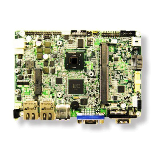
Installation 2.3 Connectors FAN1 EATX1 12VIN1 LED3 JFRT1 LAN1 DIO1 USB1 LAN2 USB2 JCOM1 USB3 COM2 DVI1 COM1 AUDIO1 CFAST1 (bottom side) INV1 LVDS1 SATA1 PWROUT1 - 12 -... -
Page 17: Jumpers
Installation Jumpers JBAT1: Clear CMOS Setting (1) If the board refuses to boot due to inappropriate CMOS settings here is how to proceed to clear (reset) the CMOS to its default values. Connector type: 2.54mm pitch 1x3-pin headers Mode Keep CMOS (Default) Clear CMOS You may need to clear the CMOS if your system cannot boot up because you forgot your password, the CPU clock setup is incorrect, or the CMOS settings... - Page 18 Installation JBAT1 PC17 - 14 -...
-
Page 19: Jat1: At/Atx Power Mode Selection
Installation JAT1: AT/ATX Power Mode Selection (2) The power mode jumper selects the power mode for the system. Connector type: 2.00mm pitch 1x2-pin headers. Mode Short AT Mode Open ATX Mode (Default) JAT1 PC17 - 15 -... -
Page 20: Jcv1: Com Port Power Selector
Installation JCV1: COM Port Power Selector (3) The pin-9 of COM1 and COM2 ports could be selected to +5V or +12V. Connector type: 2.54mm pitch 1x3-pin headers. Mode +5V (Default) +12V JCV1 PC17 - 16 -... -
Page 21: Jv1/ Jv2: Voltage/ Ri Selector For Com1/ Com2
Installation JV1/ JV2: Voltage/ RI Selector for COM1/ COM2 (4, 5) The pin-9 of COM1 and COM2 ports could be selected to +5V or +12V by JCV1 and be selected to RI by JV1/ JV2. Connector type: 2.54mm pitch 1x3-pin headers. Mode RI (Default) +5V/+12V (depends on... -
Page 22: Jrs1: Com2 Rs-232/422/485 Mode Selection
Installation JRS1: COM2 RS-232/422/485 Mode Selection (6) The onboard COM2 port can be configured to operate in RS-422 or RS-485 modes. RS-422 modes differ in the way RX/TX is being handled. Jumper JRS1 switches between RS-232 or RS-422/485 mode. All RS-232/422/482 modes are available on COM2. - Page 23 Installation JRS1 PC17 - 19 -...
-
Page 24: Jvlcd1: Lvds1 Lcd Panel Voltage Selection
Installation JVLCD1: LVDS1 LCD Panel Voltage Selection (7) The voltage of LCD panel could be selected by JVLCD1 in +5V or +3.3V. Connector type: 2.00 mm pitch 1x3-pin headers Voltage +3.3V (Default) PC17 JVLCD1 - 20 -... -
Page 25: Connectors
Installation Connectors INV1: LCD Inverter Connector (8) Connector type: 2.00mm pitch 1x5-pin box wafer connector. Description +12V on/off Brightness control PC17 INV1 - 21 -... -
Page 26: Lvds1: Lvds Connector
Installation LVDS1: LVDS Connector (9) The LVDS connector supports single channel 18-bit or 24-bit LVDS. VDD could be selected by JVLCD1 in +5V or +3.3V. Connector type: DF-13-30DP-1.25V Description Description TX1_CLK+ TX1_CLK- TX1_D0+ TX1_D0- TX1_D1+ TX1_D1- TX1_D2+ TX1_D2- TX1_D3+ TX1_D3- - 22 -... - Page 27 Installation PC17 LVDS1 - 23 -...
-
Page 28: Sata1: Serial Ata Connector
Installation SATA1: Serial ATA Connector (10) There are on board two SATA connectors, third generation SATA drives transfer data at speeds as high as 600MB/s, twice the transfer speed of first generation SATA drives. Description SATA1 PC17 - 24 -... -
Page 29: Pwrout1: Sata Power Connector
Installation PWROUT1: SATA Power Connector (11) Connector type: 2.54mm pitch 1x4-pin wafer one wall connector Description +12V PWROUT1 PC17 - 25 -... -
Page 30: Audio1: Audio Connector
Installation AUDIO1: AUDIO Connector (12) Connector type: 2.00mm pitch 2x5-pin box header. Description Description Lin_In_Left Line_In_Right MICL MICR Speaker Left Speaker Right AUDIO1 PC17 - 26 -... -
Page 31: Com2: Serial Port Connector
Installation COM2: Serial Port Connector (13) Connector type: 2.00mm pitch 2x5-pin box header. Description Description DCD#2 RXD2 TXD2 DTR#2 DSR#2 RTS#2 CTS#2 COM2 PC17 - 27 -... -
Page 32: Jcom1: Com2 Rs-422/ 485 Connector
Installation JCOM1: COM2 RS-422/ 485 Connector (14) Connector type: 2.00mm pitch 1x4 box wafer connector RS-422 RS-485 Data+ Data- JCOM1 PC17 - 28 -... -
Page 33: Usb1, 2: Usb Connectors
Installation USB1, 2: USB Connectors (15, 16) The CPU board on board supports two headers USB1, USB2 that can connect up to 4 high-speed (Data transfers at 480Mb/s), full-speed (Data transfers at 12Mb/s) or low-speed (Data transfers at 1.5Mb/s) USB devices. Connector type: 2.00mm 2x5-pin headers Description Description... -
Page 34: Dio1: Digital I/O Connector
Installation DIO1: Digital I/O Connector (17) DIO1 is a 8-bit DIO connector that supports 8-bit programmable digital Input and Output. Connector type: 2.00 mm pitch 2x5-pin headers. Description Description DIO1 DIO2 DIO3 DIO4 DIO5 DIO6 DIO7 DIO8 DIO1 PC17 - 30 -... -
Page 35: Jfrt1: Switches And Indicators
Installation JFRT1: Switches and Indicators (18) It provides connectors for system indicators that provides light indication of the computer activities and switches to change the computer status. Connector type: 2.00 mm pitch 2x5-pin headers Description Description RESET+ RESET- POWER_LED+ POWER_LED- HDD_LED+ HDD_LED- SPEAK+... - Page 36 Installation JFRT1 PC17 - 32 -...
-
Page 37: 12Vin1: Atx +12V Connector
Installation 12VIN1: ATX +12V Connector (19) PWR1 supplies the CPU operation at +12V (Vcore). Description Description +12V +12V 12VIN1 PC17 - 33 -... -
Page 38: Eatx1: Atx Feature Connector
Installation EATX1: ATX Feature Connector (20) Connector type: 2.54mm pitch 1x3-pin box wafer connector Description PS-ON 5V_SB EATX1 PC17 - 34 -... -
Page 39: Mc1: Mini-Card Socket
Installation MC1: Mini-card Socket (21) PC17 - 35 -... -
Page 40: Fan1: Cpu Fan Connector
Installation FAN1: CPU Fan Connector (22) FAN1 is a 3-pin header for the CPU fan. The fan must be a +12V fan. Description +12V FAN Speed PC17 FAN1 - 36 -... -
Page 41: Lan1, 2: Gigabit Ethernet Connectors
Installation LAN1, 2: Gigabit Ethernet Connectors (23, 24) These connectors support Gigabit Ethernet. PC17 LAN1 LAN2 - 37 -... -
Page 42: Usb3: Usb Port Connectors
Installation USB3: USB Port Connectors (25) Connector type: double stack USB type A. PC17 USB3 - 38 -... -
Page 43: Dvi1: Dvi Connector
Installation DVI1: DVI Connector (26) Connector type: DVI-I female. DVI-I Connector Description Description Description DATA2- DATA1- DATA0- DATA2+ DATA1+ DATA0+ DATA 2/4 DATA 1/3 DATA 0/5 SHIELD SHIELD SHIELD DATA 4- (LINK DATA 3- (LINK DATA 5- (LINK 1, NC 1, NC 1, NC DATA 4+ (LINK... - Page 44 Installation PC17 DVI1 - 40 -...
-
Page 45: Com1: Serial Port Connector
Installation COM1: Serial Port Connector (27) Connector type: D-Sub 9-pin male. Description Description DCD#1 DSR#1 RXD1 RTS#1 TXD1 CTS#1 DTR#1 PC17 COM1 - 41 -... -
Page 46: Cfast1: Cfast Socket
Installation CFast1: CFast Socket (28, battom side) Description SGND1 SGND2 SGND PC17 LED1 LED2 PC10 PC11 PC12 PC13 3.3V PC14 3.3V PC15 PC16 PC17 - 42 -... - Page 47 Installation CFast1 (on bottom PC17 side) - 43 -...
-
Page 48: The Installation Paths Of Cd Driver
Installation 2.3 The Installation Paths of CD Driver Windows 7 Driver Path CHIPSET \EmETXe-i250x\CHIPSET\WIN7 \EmETXe-i250x\GRAPHICS AUDIO \EmETXe-i250x\AUDIO \EmETXe-i250x\ETHERNET - 44 -... -
Page 49: Chapter 3 - Bios
BIOS Chapter 3 BIOS Chapter 3 - BIOS - 45 -... -
Page 50: Bios Main Setup
Set the Date. Use Tab to BIOS Vendor American Megatrands switch between Data elements. Core Version 4.6.5.1 Compliancy UEFI 2.3; PI 1.2 BIOS Version EasyBoard-650E 1.01 Build Date and Time 09/13/2012 14:48:24 System Date [Wed 09/26/2012] System Time [17:04:19] Select Screen Select Item... -
Page 51: Advanced Settings
BIOS System Time Set the system time. The time format is: Hour : 00 to 23 Minute : 00 to 59 Second : 00 to 59 3.2 Advanced Settings Aptio Setup Utility - Copyright (C) 2011 American Megatrends, Inc. Advanced Chipset Boot Security... -
Page 52: Acpi Settings
BIOS 3.2.1 ACPI Settings Aptio Setup Utility - Copyright (C) 2011 American Megatrends, Inc. Advanced ACPI Settings Enables or Disables BIOS ACPI Auto Configuration. Enable ACPI Auto Configuration [Disabled] Enable Hibernation [Enabled] ACPI Sleep State [S1 (CPU Stop Clock)] Select Screen Select Item Enter Select... -
Page 53: Cpu Configuration
BIOS 3.2.2 CPU Configuration The CPU Configuration setup screen varies depending on the installed processor. Aptio Setup Utility - Copyright (C) 2011 American Megatrends, Inc. Advanced XD can prevent certain classes CPU Configuration of malicious buffer overflow Aattacks when combined with a Processor Type Intel(R) Atom(TM) CPU supporting OS (Windows Server... -
Page 54: Sata Configuration
BIOS 3.2.3 SATA Configuration It allows you to select the operation mode for SATA controller. Aptio Setup Utility - Copyright (C) 2011 American Megatrends, Inc. Advanced SATA Ports (0-3) Device Names SATA Port0 Not Present if Present and Enabled. SATA Port1 GLS85SL1008A C (8.0GB SATA Controller(s) [Enabled]... -
Page 55: Usb Configuration
BIOS 3.2.4 USB Configuration Aptio Setup Utility - Copyright (C) 2011 American Megatrends, Inc. Advanced This is a workaround for OSes USB Configuration without EHCI hand-off support. The EHCI ownership change USB Devices: should be claimed by EHCI 1 Keyboard, 1 Mouse driver. -
Page 56: H/W Monitor
BIOS Device power-up delay Maximum time the device will take before it properly reports itself to the host controller. ‘Auto’ uses default value: for a Root port it is 100ms, for a Hub port the delay is taken from hub descriptor. The choice: Auto (Default); Manual Mass Storage Devices This item displays information when USB devices are detected. -
Page 57: Super Io Configuration
BIOS 3.2.6 Super IO Configuration You can use this item to set up or change the Super IO configuration for parallel ports and serial ports. Aptio Setup Utility - Copyright (C) 2011 American Megatrends, Inc. Advanced Set Parameters of Serial Port 1 F81866 Super IO Configuration F81866 Super IO Chip F81866... -
Page 58: Serial Port
BIOS Serial Port 1~2 Configuration Aptio Setup Utility - Copyright (C) 2011 American Megatrends, Inc. Advanced Enable or Disable Serial Port Serial Port 1 Configuration (COM) Serial Port [Enabled] Device Settings IO=3F8h; IRQ=4; Change Settings [Auto] Select Screen Select Item Enter Select Change Opt. -
Page 59: Chipset
BIOS 3.3 Chipset This section allows you to configure and improve your system; also, set up some system features according to your preference. Aptio Setup Utility - Copyright (C) 2011 American Megatrends, Inc. Advanced Chipset Boot Security Save & Exit Main Host Bridge Parameters Host Bridge... -
Page 60: Host Bridge Parameters
BIOS 3.3.1 Host Bridge Parameters Memory Frequency and Timing Aptio Setup Utility - Copyright (C) 2011 American Megatrends, Inc. Chipset Config Intel IGD Settings. Intel IGD Configuration ******* Memory Information ******* Memory Frequency 1067 MHz (DDR3) Total Memory 1024 MB DIMM#0 Not Present DIMM#1... -
Page 61: Intel Igd Configuration
BIOS Intel IGD Configuration Aptio Setup Utility - Copyright (C) 2011 American Megatrends, Inc. Chipset Select the Video Device which Intel IGD Configuration will be activated during POST. IGFX - Boot Type [CRT] This has no effect if LCD Panel Type [1024x768 LVDS] external graphics present. -
Page 62: Sb Configuration
BIOS 3.3.2 SB Configuration Aptio Setup Utility - Copyright (C) 2011 American Megatrends, Inc. Chipset Select a minimum assertion width of the SLP_S4# signal High Precision Event Timer Configuration High Precision Timer [Enabled] SLP_S4 Assertion Width [1-2 Seconds] Select Screen Select Item Enter Select... -
Page 63: Boot Settings
BIOS 3.4 Boot Settings The Boot menu items allow you to change the system boot options. Aptio Setup Utility - Copyright (C) 2011 American Megatrends, Inc. Advanced Chipset Boot Security Save & Exit Main Select the keyboard NumLock Boot Configuration Boot NumLock State [On] state... -
Page 64: Security
BIOS 3.5 Security Aptio Setup Utility - Copyright (C) 2011 American Megatrends, Inc. Advanced Chipset Boot Security Save & Exit Main Set Administrator Password Password Description If ONLY the Administrator’s password is set, then this only limits access to Setup and is only asked for when entering Setup. - Page 65 BIOS changing any part of your system configuration. Additionally, when a password is enabled, you can also require the BIOS to request a password every time your system is rebooted. This would prevent unauthorized use of your computer. You can determine when the password is required within the BIOS Features Setup Menu and its Security option.
-
Page 66: Save & Exit
BIOS 3.6 Save & Exit Aptio Setup Utility - Copyright (C) 2011 American Megatrends, Inc. Advanced Chipset Boot Security Save & Exit Main Exit system setup after saving Save Changes and Exit Discard Changes and Exit the changes. Restore Defaults Boot Override SATA SM: GLS85LS1008A CS 08GB Select Screen... -
Page 67: Ami Bios Checkpoints
BIOS 3.7 AMI BIOS Checkpoints 3.7.1 Checkpoint Ranges Status Code Range Description 0x01 – 0x0B SEC execution 0x0C – 0x0F SEC errors PEI execution up to and including memory 0x10 – 0x2F detection 0x30 – 0x4F PEI execution after memory detection 0x50 –... -
Page 68: Standard Checkpoints
BIOS 3.7.2 Standard Checkpoints SEC Phase Status Code Description 0x00 Not used Progress Codes 0x01 Power on. Reset type detection (soft/hard). 0x02 AP initialization before microcode loading 0x03 North Bridge initialization before microcode loading 0x04 South Bridge initialization before microcode loading 0x05 OEM initialization before microcode loading 0x06... - Page 69 BIOS PEI Phase Status Code Description Progress Codes 0x10 PEI Core is started 0x11 Pre-memory CPU initialization is started 0x12 Pre-memory CPU initialization (CPU module specific) 0x13 Pre-memory CPU initialization (CPU module specific) 0x14 Pre-memory CPU initialization (CPU module specific) 0x15 Pre-memory North Bridge initialization is started Pre-Memory North Bridge initialization (North Bridge...
- Page 70 BIOS 0x32 CPU post-memory initialization is started 0x33 CPU post-memory initialization. Cache initialization CPU post-memory initialization. Application Processor(s) 0x34 (AP) initialization CPU post-memory initialization. Boot Strap Processor 0x35 (BSP) selection CPU post-memory initialization. System Management 0x36 Mode (SMM) initialization 0x37 Post-Memory North Bridge initialization is started Post-Memory North Bridge initialization (North Bridge 0x38...
- Page 71 BIOS 0x55 Memory not installed 0x56 Invalid CPU type or Speed 0x57 CPU mismatch 0x58 CPU self test failed or possible CPU cache error CPU micro-code is not found or micro-code update is 0x59 failed 0x5A Internal CPU error 0x5B reset PPI is not available 0x5C-0x5F Reserved for future AMI error codes...
- Page 72 BIOS 0xF9 Recovery capsule is not found 0xFA Invalid recovery capsule 0xFB – 0xFF Reserved for future AMI error codes DXE Phase Status Code Description 0x60 DXE Core is started 0x61 NVRAM initialization 0x62 Installation of the South Bridge Runtime Services 0x63 CPU DXE initialization is started 0x64...
- Page 73 BIOS South Bridge DXE Initialization (South Bridge module 0x74 specific) South Bridge DXE Initialization (South Bridge module 0x75 specific) South Bridge DXE Initialization (South Bridge module 0x76 specific) South Bridge DXE Initialization (South Bridge module 0x77 specific) 0x78 ACPI module initialization 0x79 CSM initialization 0x7A –...
- Page 74 BIOS 0xA4 SCSI initialization is started 0xA5 SCSI Reset 0xA6 SCSI Detect 0xA7 SCSI Enable 0xA8 Setup Verifying Password 0xA9 Start of Setup 0xAA Reserved for ASL (see ASL Status Codes section below) 0xAB Setup Input Wait 0xAC Reserved for ASL (see ASL Status Codes section below) 0xAD Ready To Boot event 0xAE...
- Page 75 BIOS 0xD7 No Console Input Devices are found 0xD8 Invalid password 0xD9 Error loading Boot Option (LoadImage returned error) 0xDA Boot Option is failed (StartImage returned error) 0xDB Flash update is failed 0xDC Reset protocol is not available ACPI/ASL Checkpoints Status Code Description 0x01...
-
Page 76: Appendix
Appendix Appendix Appendix - 72 -... -
Page 77: Appendix A: I/O Port Address Map
Appendix Appendix A: I/O Port Address Map Each peripheral device in the system is assigned a set of I/O port addresses which also becomes the identity of the device. The following table lists the I/O port addresses used. Address Device Description 0x00000000-0x00000CF7 PCI bus 0x00000000-0x00000CF7... - Page 78 Appendix 0x000000BC-0x000000BD Programmable interrupt controller 0x000004D0-0x000004D1 Programmable interrupt controller 0x000004D0-0x000004D1 Motherboard resources 0x0000002E-0x0000002F Motherboard resources 0x0000004E-0x0000004F Motherboard resources 0x00000061-0x00000061 Motherboard resources 0x00000063-0x00000063 Motherboard resources 0x00000065-0x00000065 Motherboard resources 0x00000067-0x00000067 Motherboard resources 0x00000070-0x00000070 Motherboard resources 0x00000070-0x00000070 System CMOS/real time clock 0x00000080-0x00000080 Motherboard resources 0x00000080-0x00000080 Motherboard resources 0x00000092-0x00000092...
- Page 79 Appendix 0x00000064-0x00000064 Standard 101/102-Key or Microsoft Natural PS/2 Keyboard 0x000003F8-0x000003FF Communications Port (COM1) 0x000002F8-0x000002FF Communications Port (COM2) 0x00000378-0x0000037F Printer Port (LPT1) 0x00000010-0x0000001F Motherboard resources 0x00000022-0x0000003F Motherboard resources 0x00000044-0x0000005F Motherboard resources 0x00000072-0x0000007F Motherboard resources 0x00000084-0x00000086 Motherboard resources 0x00000088-0x00000088 Motherboard resources 0x0000008C-0x0000008E Motherboard resources 0x00000090-0x0000009F Motherboard resources...
-
Page 80: Appendix B: Interrupt Request Lines (Irq)
Appendix 0x000001CE-0x000001CF VgaSave 0x000002E8-0x000002EF VgaSave Appendix B: Interrupt Request Lines (IRQ) Peripheral devices use interrupt request lines to notify CPU for the service required. The following table shows the IRQ used by the devices on board. Level Function IRQ 9 Microsoft ACPI-Compliant System IRQ 16 PCI standard PCI-to-PCI bridge... -
Page 81: Appendix C: Bios Memory Map
Appendix Appendix C: BIOS Memory Map Address Device Description 0xA0000-0xBFFFF PCI bus 0xA0000-0xBFFFF VgaSave 0xD0000-0xD3FFF PCI bus 0xD4000-0xD7FFF PCI bus 0xD8000-0xDBFFF PCI bus 0xDC000-0xDFFFF PCI bus 0xE0000-0xE3FFF PCI bus 0xE4000-0xE7FFF PCI bus 0x7DA00000-0xFEAFFFFF PCI bus 0x7DA00000-0xFEAFFFFF Motherboard resources 0xF7800000-0xF7BFFFFF Video Controller (VGA Compatible) 0xE0000000-0xEFFFFFFF Video Controller (VGA Compatible) 0xF7C2B000-0xF7C2B00F... - Page 82 Appendix 0xFED19000-0xFED19FFF Motherboard resources 0xF8000000-0xFBFFFFFF Motherboard resources 0xFED20000-0xFED3FFFF Motherboard resources 0xFED90000-0xFED93FFF Motherboard resources 0xFED45000-0xFED8FFFF Motherboard resources 0xFEE00000-0xFEEFFFFF Motherboard resources 0x20000000-0x201FFFFF System board 0x40000000-0x401FFFFF System board - 78 -...
-
Page 83: Appendix D: Digital I/O Setting
Appendix Appendix D: Digital I/O Setting Below are the source codes written in C, please take them for Digital I/O application examples. The default I/O address is 4Eh/4Fh. C language Code #define SIO_ID 0x1010 #define SIO_INDEX 0x4E #define SIO_DATA 0x4F #define SIO_EN 0x87 #define SIO_DN... - Page 84 Appendix SetPortVal(SIO_INDEX,SIO_DN,1); // SIO - Disable if( iID == SIO_ID ) return true; return false; //--------------------------------------------------------------------------- unsigned char __fastcall TForm1::GPIO_Set(unsigned oMode,unsigned char oData) DWORD iData; // SIO - Enable SetPortVal(SIO_INDEX,SIO_EN,1); SetPortVal(SIO_INDEX,SIO_EN,1); // LDN - GPIO SetPortVal(SIO_INDEX,LDN_ADDR,1); SetPortVal(SIO_DATA,0x06,1); // GPIO5 - Mode SetPortVal(SIO_INDEX,0xA0,1);...
- Page 85 Appendix bool __fastcall TForm1::DIO_Test(int iPIN) int i = iPIN; bool bTest = true; unsigned char InData; unsigned char oMode[8] = {0x0F,0x0F,0x0F,0x0F,0xF0,0xF0,0xF0,0xF0}; unsigned char oDataL[8] = {0xF7,0xFD,0xFE,0xFB,0xEF,0xDF,0xBF,0x7F}; unsigned char oDataH[8] = {0xF8,0xF2,0xF1,0xF4,0x1F,0x2F,0x4F,0x8F}; unsigned char iData[8] = {0x10,0x20,0x40,0x80,0x08,0x02,0x01,0x04}; InData = GPIO_Set(oMode[i],oDataL[i]) & iData[i]; // Low Test if( !(InData == 0x00) ) bTest = false;...
- Page 86 Appendix Digital IO usage table (Super IO chipaset Fintek F81866D) Description Chipset Pin# Chipset Pin description DIO1 GPIO50 DIO2 GPIO51 DIO3 GPIO52 DIO4 GPIO53 DIO5 GPIO54 DIO6 GPIO55 DIO7 GPIO56 DIO8 GPIO57 - 82 -...
Need help?
Do you have a question about the EasyBoard-650E and is the answer not in the manual?
Questions and answers