
Related Manuals for Arbor Technology EmETXe-i87M0


Summary of Contents for Arbor Technology EmETXe-i87M0
- Page 1 EmETXe-i87M0 COM Express Compact ® Type 6 CPU Module User’s Manual Version 1.0 2013.12...
-
Page 2: Revision History
Revision History Version Date Description 2013/12 initial release... -
Page 3: Table Of Contents
Contents Table of Contents Preface..................iii Copyright Notice ..............iii Declaration of Conformity ..........iii CE ..................iii FCC Class A ..............iii RoHS ................iv SVHC / REACH .............iv Warning ................v Replacing the Lithium Battery ...........v Technical Support ..............v Warranty ................vi Chapter 1 - Introduction............1 1.1 The Product ..............2 1.2 About This Manual............2 1.3 Specifications ..............3... - Page 4 Content 4.2.3 SATA Configuration ..........25 4.2.4 AMT Configuration ...........26 4.2.5 USB Configuration ...........27 4.2.6 H/W Monitor ............28 4.2.7 Super IO Configuration ........29 4.2.8 Intel(R) Ethernet Network Connect ....31 4.3 Chipset ...............33 4.3.1 PCI Express Configuration ......34 4.3.2 USB Configuration ...........36 4.3.3 PCH Azalia Configuration ........37 4.3.4 Display Control ..........38 4.3.5 Graphics Configuration ........39...
-
Page 5: Preface
This product has passed the CE test for environmental specifications when shielded cables are used for external wiring. We recommend the use of shielded cables. This kind of cable is available from ARBOR. Please contact your local supplier for ordering information. -
Page 6: Rohs
RoHS ARBOR Technology Corp. certifies that all components in its products are in compliance and conform to the European Union’s Restriction of Use of Haz- ardous Substances in Electrical and Electronic Equipment (RoHS) Directive 2002/95/EC. -
Page 7: Warning
Technical Support If you have any technical difficulties, please consult the user’s manual first ftp://ftp.arbor.com.tw/pub/manual Please do not hesitate to call or e-mail our customer service when you still can- not find out the answer. -
Page 8: Warranty
Preface Warranty This product is warranted to be in good working order for a period of two years from the date of purchase. Should this product fail to be in good working order at any time during this period, we will, at our option, replace or repair it at no additional charge except as set forth in the following terms. -
Page 9: Chapter 1 Introduction
Introduction Chapter 1 Introduction - 1 -... -
Page 10: The Product
Introduction 1.1 The Product The EmETXe-i87M0 is a space-conscious CPU board of 125 mm x 95 mm to take up only small footprint in your system. By the architecture of Type 6, the board has two high-performance connectors to promise stable data passing rate. -
Page 11: Specifications
Introduction 1.3 Specifications System ® Intel 4th Generation Core™ i5 4402E 1.6GHz processor 2 x DDR3L SO-DIMM sockets, supporting up to Memory 16GB SDRAM Intel PCH QM87 Chipset ® UEFI BIOS BIOS ® 1~255 levels reset Watchdog Timer 12 x USB ports: USB Port - 8 x USB 2.0 ports - 4 x USB 3.0 ports... -
Page 12: Inside The Package
1.4 Inside the Package Before you begin installing your single board, please make sure that the following materials have been shipped: 1 x EmETXe-i87M0 COM Express CPU Module 1 x Driver CD 1 x Quick Installation Guide If any of the above items is damaged or missing, contact your vendor immediately. -
Page 13: The Installation Paths Of Cd Driver
DO install Chipset→Graphic→Audio before the rest to prevent errors. Find the drivers on CD by the following paths: Windows 8 Driver Path Chipset EmETXe-i87M0\Chipset EmETXe-i87M0\Graphic\32 Bit\Win32_V9.18.10.3107 Graphic EmETXe-i87M0\Graphic\64 Bit\win64_V9.18.10.3107 EmETXe-i87M0\Audio\win7_win8\32Bit Audio EmETXe-i87M0\Audio\win7_win8\64Bit EmETXe-i87M0\Ethernet\Win8\32Bit EmETXe-i87M0\Ethernet\Win8\64Bit EmETXe-i87M0\ME\ME9.0_5M_V9.0.2.1345... - Page 14 This page is intentionally left blank. - 6 -...
-
Page 15: Chapter 2 - Board Overview
Board Overview Chapter 2 Board Overview - 7 -... -
Page 16: What Is "Com Express
Module Type 1 and 10 support single connector with two rows (220 pins). Module Type 2, 3, 4, 5 and 6 support two connectors with four rows (440 pins). EmETXe-i87M0 is a Type-6 module. Difference between Standard Type 6 and EmETXe-i87M0 is listed as below: Module Type Standard Type 6... -
Page 17: Board Dimensions
Board Overview 2.2 Board Dimensions The following illustration shows the dimension of EmETXe-i87M0, with the mea- surements in width, depth, and height called out. 70.64 55.68 79.53 45.35 Unit: mm Ø2.6*Ø6.5 - 9 -... -
Page 18: Block Diagram
Board Overview 2.3 Block Diagram 1 x PCIex16 (Gen3) DDR3L-1600MHz 2 x SO-DIMM DDR3L sockets Configurable as 1 x PCIex8, 2 x PCIex4 2 x PCIex8 Soldered DDI3 (DP) onboard 4th Gen Intel® DDI2 (DVI) Core Processor (Haswell) DDI1 (DP) DDI1 PTN3460 Dual Chnnels... -
Page 19: Connector Pin Definition
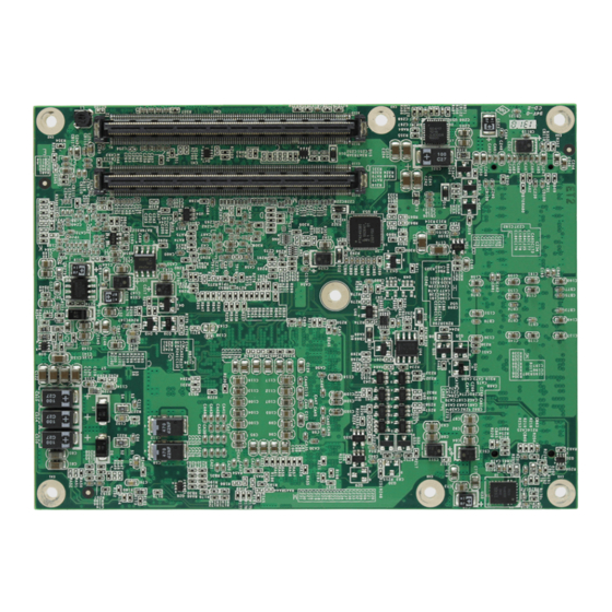
Board Overview 2.4 Connector Pin Definition Being a most commonly-used Type 6, the EmETXe-i87M0 features two board- to-board connectors on bottom side. Top Side BE BD BE BD 9 8 7 6 5 4 3 2 1 9 8 7 6... - Page 20 Board Overview COM Express AB Connector (bottom side) GND (FIXED) GND (FIXED) PCIE_RX4- PCIE_TX4- GBE0_ACT# GBE0_MDI3- GPO2 GBE0_MDI3+ LPC_FRAME# PCIE_RX3+ PCIE_TX3+ LPC_AD0 GBE0_LINK100# PCIE_RX3- PCIE_TX3- LPC_AD1 GBE0_LINK1000# GBE0_MDI2- LPC_AD2 PCIE_RX2+ PCIE_TX2+ LPC_AD3 GBE0_MDI2+ PCIE_TX2- PCIE_RX2- LPC_DRQ0# GPO3 GPI1 GBE0_MDI1- LPC_DRQ1# PCIE_RX1+ PCIE_TX1+ LPC_CLK...
- Page 21 Board Overview COM Express CD Connector (bottom side) GND (FIXED) GND (FIXED) PEG_TX1- PEG_RX1- TYPE2# TYPE1# USB_SSRX0- PEG_RX2+ USB_SSTX0- PEG_TX2+ USB_SSTX0+ USB_SSRX0+ PEG_TX2- PEG_RX2- GND (FIXED) GND (FIXED) USB_SSRX1- PEG_RX3+ USB_SSTX1- PEG_TX3+ USB_SSTX1+ USB_SSRX1+ PEG_TX3- PEG_RX3- RSVD RSVD USB_SSRX2- RSVD USB_SSTX2- RSVD USB_SSTX2+...
- Page 22 This page is intentionally left blank. - 14 -...
-
Page 23: Chapter 3 - Installation & Maintenance
Installation & Maintenance Chapter 3 Installation & Maintenance - 15 -... -
Page 24: Installing The Cpu Module On Carrier Board
1. Find the COM Express connectors on carrier board PBE-1702, which is available in Section 1.5.1 Optional Accessories on page 2. Embed EmETXe-i87M0 into PBE-1702 via COM Express connectors as below; that is, COM Express AB to AB and CD to CD. - 16 -... -
Page 25: Installing The Heatsink
Installation & Maintenance 3.2 Installing the Heatsink 1. Locate EmETXe-i87M0 mounted on PBE-1702. 2. Prepare the heatspred included in optional accessories. (See Section 1.5.1 Optional Accessories on page 4) Put heatspred on the CPU module and lock it. Make sure thermal grease in contact with CPU and chipset on CPU module. - Page 26 This page is intentionally left blank. - 18 -...
-
Page 27: Chapter 4 - Bios
BIOS Chapter 4 BIOS - 19 -... -
Page 28: Main
Advanced Chipset Boot Security Save & Exit Main Choose the system BIOS Information default language BIOS Vendor American Megatrends Core Version 4.6.5.4 BIOS Version EmETXe-i87M0 1.00 Build Date and Time 06/18/2013 20:03:34 [English] System Language System Date [Fri 06/21/2013] System Time [09:18:21] →←: Select Screen ↓↑: Select Item... - Page 29 BIOS Set the system time. Use Tab to switch between Time elements. System Time The time format is: Hour: 00 to 23 ► Minute: 00 to 59 Second: 00 to 59 Key Commands BIOS Setup Utility is mainly a key-based navigation interface. Please refer to the following key command instructions for navigation process.
-
Page 30: Advanced
BIOS 4.2 Advanced The “Advanced” setting page provides you the options to configure the details of your hardware, such as ACPI, CPU, SATA, AMT, USB and Super IO. Aptio Setup Utility - Copyright (C) 2012 American Megatrends, Inc. Main Chipset Security Save &... -
Page 31: Acpi Settings
BIOS H/W Monitor See Section 4.2.6 H/W Monitor on page 28 See Section 4.2.7 Super IO Configuration on Super IO Configuration page 29 Intel(R) Ethernet Network See Section 4.2.8 Intel(R) Ethernet Network Connect Connect on page 31 4.2.1 ACPI Settings Aptio Setup Utility - Copyright (C) 2012 American Megatrends, Inc. -
Page 32: Cpu Configuration
BIOS 4.2.2 CPU Configuration Aptio Setup Utility - Copyright (C) 2012 American Megatrends, Inc. Advanced CPU Configuration Enabled for Windows XP and Linux (OS Intel(R) Core(TM) i5-4402E CPU @ 1.60GHz optimized for Hyper- CPU Signature 306c2 Threading Technology) CPU Speed 1600 MHz and Disabled for other Processor Cores... -
Page 33: Sata Configuration
BIOS When enabled, a VMM can utilize the additional Intel Virtualization hardware capabilities provided by Vanderpool Tech- Technology nology Options: Enabled (default) or Disabled ► EIST Enable (default)/Disable Intel SpeedStep 4.2.3 SATA Configuration Aptio Setup Utility - Copyright (C) 2012 American Megatrends, Inc. Advanced SATA Controller(s) [Enabled]... -
Page 34: Amt Configuration
BIOS Identify the SATA port is connected to Solid State SATA Device Type Drive or Hard Disk Drive (default). On an edge detect from 0 to 1, the PCH starts a Spin Up Device COMRESET initialization sequence to the device. Options: Enabled or Disabled (default) ►... -
Page 35: Usb Configuration
BIOS 4.2.5 USB Configuration Aptio Setup Utility - Copyright (C) 2012 American Megatrends, Inc. Advanced USB Configuration Enables Legacy USB support. AUTO option disables legacy USB Devices: support if no USB 1 Keyboard, 1 Mouse devices are connected. DISABLE option will Legacy USB Support [Enabled] keep USB devices... -
Page 36: H/W Monitor
BIOS 4.2.6 H/W Monitor Aptio Setup Utility - Copyright (C) 2012 American Megatrends, Inc. Advanced Pc Health Status CPU temperature1 : +62˚c System temperature1 : +45˚c CPU Speed : N/A : +3.448 V VCORE : +1.802 V : +5.175 V +1.05V : +1.050 V →←: Select Screen... -
Page 37: Super Io Configuration
BIOS 4.2.7 Super IO Configuration Aptio Setup Utility - Copyright (C) 2012 American Megatrends, Inc. Advanced Super IO Configuration Set Parameters of Serial Port 1 Super IO Chip F71869E ► Serial Port 1 Configuration ► Serial Port 2 Configuration ► Parallel Port Configuration Power On After Power Fail [Power Off] →←: Select Screen... - Page 38 BIOS Serial Port 1~2/ Parallel Port Configuration Aptio Setup Utility - Copyright (C) 2012 American Megatrends, Inc. Advanced Serial Port 1/Parallel Port Configuration Enable or Disable Serial Port (COM)/ Parallel Port (LPT/ Serial/Parallel Port [Enabled] LPTE) Device Settings IO=378h; IRQ=7; Change Settings [IO=378h;...
-
Page 39: Intel(R) Ethernet Network Connect
BIOS 4.2.8 Intel(R) Ethernet Network Connect Aptio Setup Utility - Copyright (C) 2012 American Megatrends, Inc. Advanced PORT CONFIGURATION MENU Click to configure the ► NIC Configuration network device port. Blink LEDs (range 0-15 seconds) PORT CONFIGURATION INFORMATION Intel(R) 1GbE DEV 5.1.00 UEFI Driver: FFFFFF-0FF Adapter PBA:... -
Page 40: Nic Configuration
BIOS NIC Configuration Aptio Setup Utility - Copyright (C) 2012 American Megatrends, Inc. Advanced Link Speed [AutoNeg] Change link speed and Wake on LAN [Enabled] duplex for current port. →←: Select Screen ↓↑: Select Item Enter: Select +/-: Change Opt. F1: General Help F2: Previous Values F9: Optimized Defaults... -
Page 41: Chipset
BIOS 4.3 Chipset Aptio Setup Utility - Copyright (C) 2012 American Megatrends, Inc. Main Advanced Boot Security Save & Exit Chipset PCI Express PCH-IO Configuration Configuration settings ► PCI Express Configuration ► USB Configuration ► PCH Azalia Configuration System Agent (SA) Configuration ►... -
Page 42: Pci Express Configuration
BIOS 4.3.1 PCI Express Configuration Aptio Setup Utility - Copyright (C) 2012 American Megatrends, Inc. Chipset Enable or disable PCI PCI Express Configuration Express Subtractive Decode. Subtractive Decode [Disabled] ► PCI Express x1 Slot 1 ► PCI Express x1 Slot 2 PCIE Port 4 is assigned to LAN ►... - Page 43 BIOS PCI Express x1/x4 Slot (1/2) Aptio Setup Utility - Copyright (C) 2012 American Megatrends, Inc. Chipset Control the PCI PCI Express x1/x4 Slot (1/2) [Enabled] Express Root Port. ASPM Support [Disabled] PCIe Speed [Auto] Detect Non-Compliant Device [Enabled] →←: Select Screen ↓↑: Select Item Enter: Select +/-: Change Opt.
-
Page 44: Usb Configuration
BIOS 4.3.2 USB Configuration Aptio Setup Utility - Copyright (C) 2012 American Megatrends, Inc. Chipset Control each of the USB Configuration USB ports (0~13) disabling. USB Ports Per-Port Disable Control [Disabled] →←: Select Screen ↓↑: Select Item Enter: Select +/-: Change Opt. F1: General Help F2: Previous Values F9: Optimized Defaults... -
Page 45: Pch Azalia Configuration
BIOS 4.3.3 PCH Azalia Configuration Aptio Setup Utility - Copyright (C) 2012 American Megatrends, Inc. Chipset Control Detection of PCH Azalia Configuration the Azalia device. Disabled = Azalia will Azalia [Enabled] be unconditionally disabled Enabled = Azalia will be unconditionally Enabled Auto = Azalia will be enabled if present,... -
Page 46: Display Control
BIOS 4.3.4 Display Control Aptio Setup Utility - Copyright (C) 2012 American Megatrends, Inc. Chipset Select the Video Display Control Device which will be activated during POST. Boot Display [CRT] This has no effect if LCD Panel Type [1024x768 LVDS] external graphics LVDS Channel Type [Single]... -
Page 47: Graphics Configuration
BIOS 4.3.5 Graphics Configuration Aptio Setup Utility - Copyright (C) 2012 American Megatrends, Inc. Chipset Select which of IGFX/ Primary Display [Auto] PEG/PCI Graphics Internal Graphics [Auto] device should be Primary Display Or select SG for Switchable Gfx. →←: Select Screen ↓↑: Select Item Enter: Select +/-: Change Opt. -
Page 48: Memory Configuration
BIOS 4.3.6 Memory Configuration Aptio Setup Utility - Copyright (C) 2012 American Megatrends, Inc. Chipset Memory Information Memory RC Version 1.4.0.3 Memory Frequency 1600 Mhz Total Memory 16384 MB (DDR3) Memory Voltage 1.35v DIMM#1 8192 MB (DDR3) DIMM#2 8192 MB (DDR3) CAS Latency (tCL) Minimum delay time CAS to RAS (tRCDmin) -
Page 49: Boot
BIOS 4.4 Boot Aptio Setup Utility - Copyright (C) 2012 American Megatrends, Inc. Main Advanced Chipset Security Save & Exit Boot Select the keyboard Boot Configuration NumLock state Bootup NumLock State [On] Quiet Boot [Enabled] Boot Option Priorities →←: Select Screen ↓↑: Select Item Enter: Select +/-: Change Opt. -
Page 50: Security
BIOS 4.5 Security The Security menu sets up the administrator password. Aptio Setup Utility - Copyright (C) 2012 American Megatrends, Inc. Main Advanced Chipset Boot Security Save & Exit Set Administrator Password Description Password Minimum length Maximum length Administrator Password →←: Select Screen ↓↑: Select Item Enter: Select... -
Page 51: Save & Exit
BIOS 4.6 Save & Exit Aptio Setup Utility - Copyright (C) 2012 American Megatrends, Inc. Main Advanced Chipset Boot Security Save & Exit Exit system setup Save Changes and Exit after saving the Discard Changes and Exit changes. Restore Defaults Boot Override →←: Select Screen ↓↑: Select Item... - Page 52 This page is intentionally left blank. - 44 -...
-
Page 53: Appendix
Appendix Appendix - 45 -... -
Page 54: Appendix A: I/O Port Address Map
Appendix Appendix A: I/O Port Address Map Each peripheral device in the system is assigned a set of I/O port addresses which also becomes the identity of the device. The following table lists the I/O port addresses used. Address Device Description 0x00001854-0x00001857 Motherboard resources 0x00000020-0x00000021... - Page 55 Appendix 0x00000093-0x0000009F Direct memory access controller 0x000000C0-0x000000DF Direct memory access controller Intel(R) 8 Series/C220 Series SMBus Con- 0x0000F040-0x0000F05F troller - 8C22 0x00000060-0x00000060 Standard PS / 2 Keyboard 0x00000064-0x00000064 Standard PS / 2 Keyboard 0x00000378-0x0000037F Printer Port (LPT1) 0x000003F8-0x000003FF Communications Port (COM1) 0x000002F8-0x000002FF Communications Port (COM2) 0x00000D00-0x0000FFFF...
- Page 56 Appendix 0x00000092-0x00000092 Motherboard resources 0x000000B2-0x000000B3 Motherboard resources 0x00000680-0x0000069F Motherboard resources 0x0000FFFF-0x0000FFFF Motherboard resources 0x0000FFFF-0x0000FFFF Motherboard resources 0x0000FFFF-0x0000FFFF Motherboard resources 0x00001C00-0x00001CFE Motherboard resources 0x00001D00-0x00001DFE Motherboard resources 0x00001E00-0x00001EFE Motherboard resources 0x00001F00-0x00001FFE Motherboard resources 0x00001800-0x000018FE Motherboard resources 0x0000164E-0x0000164F Motherboard resources Intel(R) 8 Series SATA AHCI Controller - 0x0000F0D0-0x0000F0D7 8C03 Intel(R) 8 Series SATA AHCI Controller -...
-
Page 57: Appendix B: Bios Memory Mapping
Appendix Appendix B: BIOS Memory Mapping Address Device Description 0xFF000000-0xFFFFFFFF Intel(R) 82802 Firmware Hub Device 0xFF000000-0xFFFFFFFF Motherboard resources Intel(R) 8 Series/C220 Series PCI Express 0xF7C00000-0xF7CFFFFF Root Port #3 - 8C14 0xF7C00000-0xF7CFFFFF PCI standard PCI-to-PCI bridge 0xF7D30000-0xF7D33FFF High Definition Audio Controller 0xFED00000-0xFED003FF High Precision Event Timer, HPET 0xF7800000-0xF7BFFFFF... -
Page 58: Appendix C: Interrupt Request Lines (Irq)
Appendix 0xF8000000-0xFBFFFFFF Motherboard resources 0xFED20000-0xFED3FFFF Motherboard resources 0xFED90000-0xFED93FFF Motherboard resources 0xFED45000-0xFED8FFFF Motherboard resources 0xFEE00000-0xFEEFFFFF Motherboard resources 0xF7FEF000-0xF7FEFFFF Motherboard resources 0xF7FF0000-0xF7FF0FFF Motherboard resources 0xF7D00000-0xF7D1FFFF Intel(R) Ethernet Connection I217-LM 0xF7D3D000-0xF7D3DFFF Intel(R) Ethernet Connection I217-LM 0xF7D20000-0xF7D2FFFF Intel (R) USB 3.0 Extensible Host Controller Intel(R) 8 Series SATA AHCI Controller - 0xF7D3A000-0xF7D3A7FF 8C03... -
Page 59: Appendix D: Watchdog Timer (Wdt) Setting
Appendix Appendix D: Watchdog Timer (WDT) Setting WDT is widely used for industry application to monitor the activity of CPU. Ap- plication software depends on its requirement to trigger WDT with adequate timer setting. Before WDT time out, the functional normal system will reload the WDT. - Page 60 Appendix /* Configuration and Control Register - Enable WDTOUT10# output */ bData = SMB_Byte_READ(SMB_PORT_AD,SMB_DEVICE_ADD,0x01); bData = bData | 0x20; SMB_Byte_WRITE(SMB_PORT_AD,SMB_DEVICE_ADD,0x01,bData); delay(DELAY_TIME); /* Watchdog Timer Control Register */ SMB_Byte_WRITE(SMB_PORT_AD,SMB_DEVICE_ADD,0x36,0x28); delay(DELAY_TIME); /* WDTOUT10 Control Register - Enable WDTOUT10 Output Timer */ SMB_Byte_WRITE(SMB_PORT_AD,SMB_DEVICE_ADD,0x35,(0x80|WDTCount)); int WDT_Count(void) unsigned char bData; bData = SMB_Byte_READ(SMB_PORT_AD,SMB_DEVICE_ADD,0x35) & 0xFF7F; return bData; unsigned char SMB_Byte_READ(int SMPORT, int DeviceID, int iREG_INDEX) unsigned char iData; unsigned char iFlag; int iError = 0; outportb(SMPORT+00, 0x1E); iFlag = inportb(SMPORT+00); if( iError++ > 0x8000 ) return 2; while( ( iFlag & 0x9F ) != 0 ); outportb(SMPORT+04, DeviceID+1); outportb(SMPORT+03, iREG_INDEX); outportb(SMPORT+02, 0x48); iError = 0; if( iError++ > 0x8000) return 2; if( ( inportb(SMPORT+0x00) & 0x06 ) == 0x06 ) return 1; while( (inportb(SMPORT+0x00) & 0x06 ) != 0x02 ); iData = inportb(SMPORT+05); return iData; - 52 -...
- Page 61 Appendix void SMB_Byte_WRITE(int SMPORT, int DeviceID, int oREG_INDEX, int oREG_DATA) unsigned char iFlag; int iError = 0; outportb(SMPORT+00, 0x1E); iFlag = inportb(SMPORT+00); if( iError++ > 0x8000 ) return; while( ( iFlag & 0x9F ) != 0 ); outportb(SMPORT+04, DeviceID); outportb(SMPORT+03, oREG_INDEX); outportb(SMPORT+05, oREG_DATA); outportb(SMPORT+02, 0x48); iError = 0; iError++; if( iError > 0x8000) return; if( ( inportb(SMPORT+0x00) & 0x06 ) == 0x06 ) return; while( (inportb(SMPORT+0x00) & 0x06 ) != 0x02 ); - 53 -...
-
Page 62: Appendix E: Digital I/O Setting
Appendix Appendix E: Digital I/O Setting Below are the source codes written in C, please take them for Digital I/O application examples. The default I/O address is 6Eh. /*----- Include Header Area -----*/ #include “math.h” #include “stdio.h” #include “dos.h” #define DELAY_TIME int SMB_PORT_AD = 0xF040;... - Page 63 Appendix unsigned char iFlag; int iError = 0; outportb(SMPORT+00, 0x1E); iFlag = inportb(SMPORT+00); if( iError++ > 0x8000 ) return 2; while( ( iFlag & 0x9F ) != 0 ); outportb(SMPORT+04, DeviceID+1); outportb(SMPORT+03, iREG_INDEX); outportb(SMPORT+02, 0x48); iError = 0; if( iError++ > 0x8000) return 2; if( ( inportb(SMPORT+0x00) & 0x06 ) == 0x06 ) return 1; while( (inportb(SMPORT+0x00) & 0x06 ) != 0x02 ); iData = inportb(SMPORT+05); return iData; void SMB_Byte_WRITE(int SMPORT, int DeviceID, int oREG_INDEX, int oREG_DATA) unsigned char iFlag; int iError = 0; outportb(SMPORT+00, 0x1E); iFlag = inportb(SMPORT+00); if( iError++ > 0x8000 ) return; while( ( iFlag & 0x9F ) != 0 ); outportb(SMPORT+04, DeviceID); outportb(SMPORT+03, oREG_INDEX); outportb(SMPORT+05, oREG_DATA); outportb(SMPORT+02, 0x48); iError = 0; iError++; if( iError > 0x8000) return; if( ( inportb(SMPORT+0x00) & 0x06 ) == 0x06 ) return; while( (inportb(SMPORT+0x00) & 0x06 ) != 0x02 ); - 55 -...
Need help?
Do you have a question about the EmETXe-i87M0 and is the answer not in the manual?
Questions and answers