Xilinx VC707 Getting Started
Virtex-7 fpga
Hide thumbs
Also See for VC707:
- User manual (116 pages) ,
- Manual (82 pages) ,
- Quick start manual (18 pages)
Table of Contents
Advertisement
Quick Links
Download this manual
See also:
User Manual
Advertisement
Table of Contents

Related Manuals for Xilinx VC707


Summary of Contents for Xilinx VC707
- Page 1 Getting Started with the Virtex-7 FPGA VC707 Evaluation Kit UG848 (v1.4.1) October 14, 2015 XPM 0402902-04...
-
Page 2: Revision History
(including loss of data, profits, goodwill, or any type of loss or damage suffered as a result of any action brought by a third party) even if such damage or loss was reasonably foreseeable or Xilinx had been advised of the possibility of the same. -
Page 3: Table Of Contents
............. 2 Chapter 1: Getting Started with the Virtex-7 FPGA VC707 Evaluation Kit Introduction . - Page 4 Getting Started with the VC707 Evaluation Kit Send Feedback UG848 (v1.4.1) October 14, 2015...
-
Page 5: Chapter 1: Getting Started With The Virtex-7 Fpga Vc707 Evaluation Kit
This document describes how to use the materials provided in the VC707 Evaluation Kit to set up the VC707 board and a host computer to run two reference designs, which test and demonstrate some of the key features of the XC7VX485T FPGA and the VC707 board: •... -
Page 6: Host Computer Requirements
The BIST design uses a terminal program to communicate between the host computer and the VC707 board. To configure the host computer COM port for this purpose: Connect the VC707 board to the host computer and power supply as shown in Figure 1-1. - Page 7 In the properties window, select the Port Settings tab, verify the settings match the values shown in Figure 1-3 and then click Advanced. X-Ref Target - Figure 1-3 UG848_c1_03_071112 Figure 1-3: Port Settings Getting Started with the VC707 Evaluation Kit www.xilinx.com Send Feedback UG848 (v1.4.1) October 14, 2015...
- Page 8 LogMeTT download page. To communicate with the VC707 board, configure the New Connection and Serial Port settings as shown in Figure 1-5. These settings must match the host computer COM port...
- Page 9 Preliminary Setup Verify Jumpers are in Default Positions Verify the jumpers on the VC707 board are positioned as shown in Table 1-1. See Figure 1-6 for the location of the jumpers. Table 1-1: Default Jumper Settings Schematic Default Jumper Callout...
-
Page 10: Built-In Self Test
Figure 1-6: VC707 Board Jumper Header Locations Built-In Self Test The BIST tests several XC7VX485T FPGA and VC707 board features. The BIST interface is a menu of tests displayed by a terminal program running on the host computer. Project Files... - Page 11 Built-In Self Test Run BIST Complete the tasks under Preliminary Setup, page Connect the VC707 board to the host computer and power supply as shown in Figure 1-7. X-Ref Target - Figure 1-7 USB cable standard-A plug Board Power Host...
-
Page 12: Ams 101 Card Demonstration
The GUI was developed with National Instruments LabVIEW 2011 software. To enable use of the GUI without a LabVIEW license, Xilinx bundled the LabVIEW run-time engine with the GUI installer. During the installation process, the run-time engine is installed on the www.xilinx.com... - Page 13 Navigate to the software version that you are using, click + to expand the document type list, and click Targeted Reference Designs. Download the “AMS Targeted Reference Design for Virtex-7 FPGA VC707 Evaluation Kit” zip file. After downloading the design files, open the xadc_eval_design_vc707_vxx folder and unzip the files to a working directory on the host computer.
- Page 14 Reference buffer for DAC. Turn off the VC707 board power (SW12) before installing the AMS 101 card on the VC707 board XADC header J35. Plug the AMS 101 Card into the XADC header J35 on the VC707 board as shown in Figure 1-11.
- Page 15 AMS 101 Card Demonstration After the AMS Evaluator installer files are installed, a red Xilinx logo (“X”) is displayed on the host PC desktop. Click the “X” to open the AMS Evaluator tool (Figure 1-12). X-Ref Target - Figure 1-12...
-
Page 16: Next Steps
Review and run the reference designs available at the VC707 Evaluation Kit website from the Docs & Designs tab. Additional Information VC707 board reference design files, user guides, schematics, and bill of materials, can be downloaded from the VC707 Evaluation Kit website. -
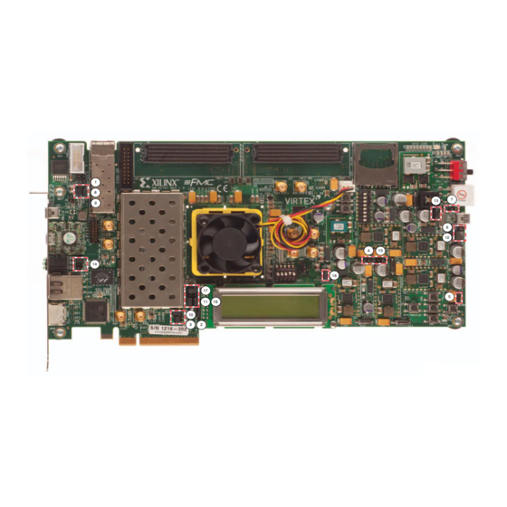
Page 17: Appendix A: Vc707 Board Components
VC707 Board Components The VC707 board block diagram is shown in Figure A-1. The VC707 board schematics are available for download from the VC707 Evaluation Kit product page on the Docs & Designs tab at VC707 Evaluation Kit website Caution! The VC707 board can be damaged by electrostatic discharge (ESD). -
Page 18: Feature Descriptions
Silicon Labs SI570BAB0000544DG 156.250 MHz default frequency (back side of board) J31, J32 User SMA clock Rosenberger 32K10K-400L5 J25, J26 GTX transceiver SMA reference clock Rosenberger 32K10K-400L5 www.xilinx.com Getting Started with the VC707 Evaluation Kit Send Feedback UG848 (v1.4.1) October 14, 2015... - Page 19 Feature Descriptions Table A-1: VC707 Board Component Descriptions (Cont’d) Schematic Reference 0381418 Callout Component Description Notes Designator Page Number Jitter attenuated clock (back side of board) Silicon Labs SI5324C-C-GM GTX transceiver Quad 111 – Quad 119 Embedded within FPGA U1 12 –...
- Page 20 Appendix A: VC707 Board Components www.xilinx.com Getting Started with the VC707 Evaluation Kit Send Feedback UG848 (v1.4.1) October 14, 2015...
-
Page 21: Appendix B: Additional Resources
Topics include design assistance, advisories, and troubleshooting tips. References The most up to date information related to the VC707 board and its documentation is available on these websites: Virtex-7 VC707 Evaluation Kit... - Page 22 Appendix B: Additional Resources www.xilinx.com Getting Started with the VC707 Evaluation Kit Send Feedback UG848 (v1.4.1) October 14, 2015...
- Page 23 For any breach by Xilinx of this limited warranty, the exclusive remedy of Customer and the sole liability of Xilinx shall be, at the option of Xilinx, to replace or repair the affected products, or to refund to Customer the price of the affected products. The availability of replacement products is subject to product discontinuation policies at Xilinx.
- Page 24 Printed in Singapore...
Need help?
Do you have a question about the VC707 and is the answer not in the manual?
Questions and answers