Xilinx VC707 Manual
Ethernet design
Hide thumbs
Also See for VC707:
- User manual (116 pages) ,
- Manual (82 pages) ,
- Getting started (24 pages)
Advertisement
Quick Links
Advertisement

Related Manuals for Xilinx VC707


Summary of Contents for Xilinx VC707
- Page 1 VC707 Ethernet Design October 2012 XTP148...
-
Page 2: Revision History
NOTICE OF DISCLAIMER: The information disclosed to you hereunder (the “Information”) is provided “AS-IS” with no warranty of any kind, express or implied. Xilinx does not assume any liability arising from your use of the Information. You are responsible for obtaining any rights you may require for your use of this Information. - Page 3 Overview VC707 Board VC707 Setup Run SGMII Ethernet Example Design References Note: This presentation applies to the VC707...
- Page 4 VC707 Supports SGMII Capability – Board TX to Host LogiCORE Ethernet Example Design – RDF0164.zip – Available through http://www.xilinx.com/vc707 – Content generated using AR46384 LogiCORE IP Tri-Mode Ethernet MAC – See UG777 for details Note: Presentation applies to the VC707...
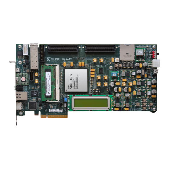
- Page 5 Xilinx VC707 Board Note: Presentation applies to the VC707...
- Page 6 ISE Software Requirements Xilinx ISE 14.3 software Note: Presentation applies to the VC707...
- Page 7 ChipScope Pro Software Requirement Xilinx ChipScope Pro 14.3 software Note: Presentation applies to the VC707...
- Page 8 ChipScope Pro Software Requirement Wireshark Protocol Analyzer available at http://www.wireshark.org/ Note: Presentation applies to the VC707...
- Page 9 Download VC707 Ethernet Design Unzip the VC707 Ethernet Design Files (14.3 CES) – Available through http://www.xilinx.com/vc707 Note: Presentation applies to the VC707...
- Page 10 VC707 Setup Connect a USB Type-A to Micro-B cable to the USB JTAG (Digilent) connector on the VC707 board – Connect this cable to your PC...
- Page 11 VC707 Setup Connect a Ethernet cable to the VC707 – Connect this cable to your PC – Power on the VC707 board...
- Page 12 VC707 Setup Set SW2 to 01000000 (1 = on, Position 1 → Position 8) This the device to 1 Gbps and turns off the packet generator...
- Page 13 Run Ethernet Example Design Open ChipScope Pro and select JTAG Chain → Digilent USB Cable… Verify 30 MHz operation and click OK (2) Note: Presentation applies to the VC707...
- Page 14 Run Ethernet Example Design Click OK (1) Note: Presentation applies to the VC707...
- Page 15 Run Ethernet Example Design Right-click DEV:0 MyDevice0 (XC7VX485T) and select Configure… Select <Design Path>\ready_for_download\vc707_sgmii.bit Note: Presentation applies to the VC707...
- Page 16 Run Ethernet Example Design Open Wireshark and select Capture → Options…...
- Page 17 Run Ethernet Example Design Select your PC’s Gigabit Ethernet connection; click on Capture filter...
- Page 18 Run Ethernet Example Design Type in the following filter and click OK: Ethernet address da:01:02:03:04:05 ether host da:01:02:03:04:05 Note: Presentation applies to the VC707...
- Page 19 Run Ethernet Example Design Click Start Note: Presentation applies to the VC707...
- Page 20 Run Ethernet Example Design Open your Network Connections control panel Right click on the Gigabit network connection and select Status The status dialog will show you the speed and number of packets Note: Presentation applies to the VC707...
- Page 21 Run Ethernet Example Design Wireshark should show no packets...
- Page 22 Run Ethernet Example Design The status dialog shows a few packets received Note: Presentation applies to the VC707...
- Page 23 Run Ethernet Example Design Set SW2 to 01100000 (1 = on, Position 1 → Position 8) for a moment to run the packet generator Set SW2 back to 01000000...
- Page 24 Run Ethernet Example Design Wireshark captures and displays the actual packets...
- Page 25 Run Ethernet Example Design Select a packet in the upper panel...
- Page 26 Run Ethernet Example Design Use the arrow keys to move to the next packet...
- Page 27 Run Ethernet Example Design Viewing several packets, you can see a simple changing pattern...
- Page 28 References...
- Page 29 References Tri-Mode Ethernet Media Access Controller – Tri-Mode Ethernet MAC Product Overview • http://www.xilinx.com/products/intellectual-property/TEMAC.htm – Tri-Mode Ethernet MAC Data Sheet – DS818 • http://www.xilinx.com/support/documentation/ip_documentation/ tri_mode_eth_mac/v5_2/ds818_tri_mode_eth_mac.pdf – LogiCORE IP Tri-Mode Ethernet MAC User Guide – UG777 • http://www.xilinx.com/support/documentation/ip_documentation/ tri_mode_eth_mac/v5_2/ug777_tri_mode_eth_mac.pdf...
- Page 30 Documentation...
- Page 31 Documentation Virtex-7 – Virtex-7 FPGA Family • http://www.xilinx.com/products/silicon-devices/fpga/virtex-7/index.htm VC707 Documentation – Virtex-7 FPGA VC707 Evaluation Kit • http://www.xilinx.com/products/boards-and-kits/EK-V7-VC707-G.htm – VC707 User Guide • http://www.xilinx.com/support/documentation/boards_and_kits/ ug885_VC707_Eval_Bd.pdf...
Need help?
Do you have a question about the VC707 and is the answer not in the manual?
Questions and answers