Advertisement
Quick Links
Advertisement

Subscribe to Our Youtube Channel
Related Manuals for Xilinx VCU118


Summary of Contents for Xilinx VCU118
- Page 1 VCU118 Software Install and Board Setup October 2017 XTP449...
-
Page 2: Revision History
NOTICE OF DISCLAIMER: The information disclosed to you hereunder (the “Information”) is provided “AS-IS” with no warranty of any kind, express or implied. Xilinx does not assume any liability arising from your use of the Information. You are responsible for obtaining any rights you may require for your use of this Information. - Page 3 VCU118 Software Install and Board Setup Xilinx VCU118 Board Software Requirements VCU118 Hardware Setup UART Driver Install Clock Setup Ethernet Setup Optional Hardware Setup References Note: This presentation applies to the VCU118...
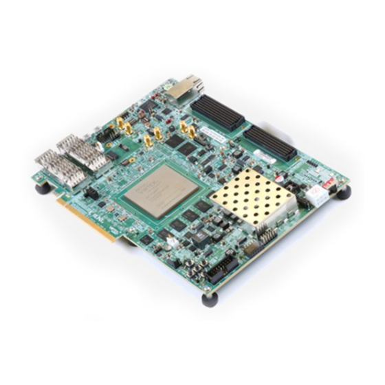
- Page 4 Xilinx VCU118 Board...
-
Page 5: Software Requirements
Software Requirements Xilinx Vivado Design Suite 2017.3.1, Design Edition with SDK – Note: 2017.3.1 has final production speed files for the Rev 2.0 VCU118 Silicon – This installs over your existing 2017.3 Vivado tools Note: Presentation applies to the VCU118... - Page 6 Software Requirements The Rev. 2.0 VCU118 board has a -2 Production device and VCCINT is set to 0.85 V DS923 notes in this case, the speed grade is considered to -2LE Note: Presentation applies to the VCU118...
- Page 7 Kit Hardware contents – VCU118 Board – QSFP+ Loopback – FMC+ Loopback – Samtec FireFly Loopback – XM107 FMC Loopback – PCIe Loopback board – Ethernet cable – Three Micro USB cables – Power supply Note: Presentation applies to the VCU118...
-
Page 8: Hardware Setup
Hardware Setup Set JTAG mode (M[2:0] = 101) for downloading Disable System Controller booting (Position 1 off) Set SW16 to 0101 (1 = on, Position 1 → Position 4) Note: JTAG mode is required for downloading bitstreams... - Page 9 VCU118 Hardware Setup QSFP Loopback Adapter – http://www.molex.com – QSFP+ Universal Loopback Adapter, 0dB – Part # 74763-0020 Insert this adapter into the Top QSFP cage (J1) on the VCU118 Note: Presentation applies to the VCU118...
- Page 10 VCU118 Hardware Setup Connect a Micro USB cable to the PCIe Loopback card for power – Connect this cable to your PC Attach to the PCIe connector (U2) on the VCU118 Note: KCU105 board shown...
- Page 11 VCU118 Hardware Setup Attach the FMC XM107 board to the J2 HPC1 FMC connector...
- Page 12 VCU118 Hardware Setup Attach the FMC+ Loopback board to the J22 HPC FMC+ connector...
- Page 13 VCU118 Hardware Setup Samtec FireFly Loopback – https://www.samtec.com/optics/optical-cable/mid-board/firefly – Part # HDR-190945-01-ECUE Attach the Samtec FireFly Loopback...
- Page 14 FireFly Insertion and Removal From Samtec PDF: – FireFly Mating...
- Page 15 VCU118 Hardware Setup Connect the power supply to the VCU118 (J15) – Connect this cable to a power outlet Note: Presentation applies to the VCU118...
- Page 16 USB JTAG (Digilent) and to the USB UART connectors on the VCU118 board – Connect these cables to your PC – Power on the VCU118 board for the UART driver installation Note: Presentation applies to the VCU118...
- Page 17 UART Driver Install Install Si Labs CP210x USB UART Drivers – Refer to UG1033 for details on installing the USB to UART Drivers Note: Presentation applies to the VCU118...
- Page 18 – The Enhanced COM Port is the System Controller COM Port – The COM Port numbers will vary from system to system These COM Port Numbers will be used in several of the tutorials Note: Presentation applies to the VCU118...
-
Page 19: Terminal Setup
Terminal Setup Refer to UG1036 regarding Tera Term installation Board Power must be on before starting Tera Term Start the Terminal Program – Select your USB Com Port – Set the baud to 115200 Note: See AR63771 regarding SDK Terminal Program... - Page 20 Terminal Setup If 115200 UART output occurs while set to 9600, you may need to reset Tera Term. From the menu select: Control -> Reset Terminal Note: Presentation applies to the VCU118...
- Page 21 Setting the clocks with the System Controller GUI See XTP447 for details on using the System Controller GUI Select the Set tab underneath the Clocks tab Enter 156.25 for the Si5328 and click Set Si5328 Frequency Note: Presentation applies to the VCU118...
- Page 22 Setting FMC HPC clock With the FMC+ Loopback card attached, select the XM107 tab For the IBERT FMC+ testing, set 156.25, and click Set SI570 Note: Presentation applies to the VCU118...
-
Page 23: Ethernet Setup
Ethernet Setup Open the Windows Control Panel – Set to View by Category Click on “View network status and tasks” Note: Presentation applies to the VCU118... - Page 24 Ethernet Setup Click on “Change adapter settings” Note: Presentation applies to the VCU118...
- Page 25 Ethernet Setup Right-click on the Gigabit Ethernet Adapter that you will be using for this test and select Properties Note: Presentation applies to the VCU118...
- Page 26 Ethernet Setup Click Configure – Set the Link Speed & Duplex to Auto Negotiation then click OK Note: Presentation applies to the VCU118...
- Page 27 Ethernet Setup Reopen the properties after the last step Double-click the Internet Protocol Version 4 Set your host (PC) to this IP Address: Note: Remember to restore your IP settings when finished...
- Page 28 Optional Hardware Setup A second QSFP Loopback Adapter – http://www.molex.com – QSFP+ Universal Loopback Adapter, 5dB – Part # 74763-0025 Insert this adapter into the Bottom QSFP cage (J96) on the VCU118 Note: Presentation applies to the VCU118...
- Page 29 Optional Hardware Setup Connect PMOD headers Both J52 and J53: – 1 to 2 – 3 to 4 – 5 to 6 – 7 to 8 Note: Presentation applies to the VCU118...
- Page 30 SMA Blocking Capacitors – Required for MGT226 and MGT233 SMA connections – Not needed on Rev 2.0 boards – www.minicircuits.com – Part number: BLK-18-S+ Optional: Splitters – www.minicircuits.com – Part number: ZFRSC-42-S+ Note: Presentation applies to the VCU118...
- Page 31 – MGT226_CLK0, J30, J31 (Black) – MGT233_CLK0, J32, J33 (Yellow) – USER_CLK, J34, J35 (Red) MGT226 and MGT233 require DC Blocking Capacitors – On all VCU118 boards through Rev 1.1 Use splitters if desired Note: Presentation applies to the VCU118...
- Page 32 References...
- Page 33 References Vivado Release Notes – Vivado Design Suite User Guide - Release Notes – UG973 • https://www.xilinx.com/support/documentation/sw_manuals/xilinx2017_3/ ug973-vivado-release-notes-install-license.pdf – Vivado Design Suite 2017 - Vivado Known Issues • https://www.xilinx.com/support/answers/68923.html Vivado Programming and Debugging – Vivado Design Suite Programming and Debugging User Guide – UG908 •...
- Page 34 Documentation...
- Page 35 – Virtex UltraScale+ FPGA VCU118 Evaluation Kit • https://www.xilinx.com/products/boards-and-kits/vcu118.html – VCU118 Board User Guide – UG1224 • https://www.xilinx.com/support/documentation/boards_and_kits/vcu118/ ug1224-vcu118-eval-bd.pdf – VCU118 Evaluation Kit Quick Start Guide User Guide – XTP453 • https://www.xilinx.com/support/documentation/boards_and_kits/vcu118/ xtp453-vcu118-quickstart.pdf – VCU118 - Known Issues and Release Notes Master Answer Record • https://www.xilinx.com/support/answers/68268.html...
Need help?
Do you have a question about the VCU118 and is the answer not in the manual?
Questions and answers