Xilinx VC707 Manual
Built-in self test flash application
Hide thumbs
Also See for VC707:
- User manual (116 pages) ,
- Manual (53 pages) ,
- Getting started (24 pages)
Advertisement
Quick Links
Advertisement

Related Manuals for Xilinx VC707


Summary of Contents for Xilinx VC707
- Page 1 VC707 Built-In Self Test Flash Application April 2015 XTP205...
-
Page 2: Revision History
NOTICE OF DISCLAIMER: The information disclosed to you hereunder (the “Information”) is provided “AS-IS” with no warranty of any kind, express or implied. Xilinx does not assume any liability arising from your use of the Information. You are responsible for obtaining any rights you may require for your use of this Information. - Page 3 Xilinx VC707 Board Software Requirements VC707 Setup VC707 BIST (Built-In Self Test) Run the USB Design Compile VC707 BIST Design Program VC707 with BIST Design Run the USB2 Design Run the LwIP Ethernet Design References Note: This presentation applies to the VC707...
- Page 4 – The Built-In System Test (BIST) application uses an IPI MicroBlaze system to verify board functionality. A UART based terminal program interface offers users a menu of tests to run. Block Design Source – VC707 BIST Design Files (2015.1 C) ZIP file – Available through http://www.xilinx.com/vc707 Note: Presentation applies to the VC707...
- Page 5 – Peripherals: AXI USB2, AXI Ethernet, AXI EMC, AXI IIC, AXI GPIO, AXI UART 16550, XADC Wizard – Other IP: Constant, Concat, gte2_top • Vivado Design Suite Tcl Command Reference Guide (UG835) • Designing IP Subsystems Using IP Integrator (UG994) Note: Presentation applies to the VC707...
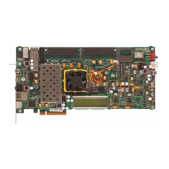
- Page 6 Xilinx VC707 Board...
-
Page 7: Vivado Software Requirements
Vivado Software Requirements Xilinx Vivado Design Suite 2015.1, Design Edition + SDK – Combined installer Note: Presentation applies to the VC707... - Page 8 VC707 Setup Connect a USB Type-A to Mini-B cable to the USB UART connector on the VC707 board – Connect this cable to your PC...
- Page 9 VC707 Setup Connect a USB Type-A to Micro-B cable to the USB JTAG (Digilent) connector on the VC707 board – Connect this cable to your PC – Power on the VC707 board for UART Drivers Installation...
- Page 10 VC707 Setup Install USB UART Drivers – Refer to UG1033 for details on installing the USB to UART Drivers Note: Presentation applies to the VC707...
- Page 11 VC707 Setup Reboot your PC if necessary Right-click on My Computer and select Properties – Select the Hardware tab – Click on Device Manager Note: Presentation applies to the VC707...
- Page 12 VC707 Setup Expand the Ports Hardware – Right-click on Silicon Labs CP210x USB to UART Bridge and select Properties Note: Presentation applies to the VC707...
- Page 13 VC707 Setup Under Port Settings tab – Click Advanced – Set the COM Port to an open Com Port setting from COM1 to COM4 Note: Presentation applies to the VC707...
- Page 14 VC707 Setup Refer to UG1036 regarding Tera Term installation Board Power must be on before starting Tera Term Start the Terminal Program – Select your USB Com Port – Set the baud to 9600 Note: Presentation applies to the VC707...
- Page 15 VC707 Setup Unzip the VC707 BIST Design Files (2015.1 C) ZIP file – Available through http://www.xilinx.com/vc707 Note: Presentation applies to the VC707...
- Page 16 VC707 BIST Open a Vivado Tcl Shell: Start → All Programs → Xilinx Design Tools → Vivado 2015.1 → Vivado 2015.1 Tcl Shell Note: Presentation applies to the VC707...
- Page 17 VC707 BIST Download the BIST bitstream with Vivado In the Vivado Tcl Shell type: cd C:/vc707_bist/ready_for_download source bist_download.tcl Note: Presentation applies to the VC707...
- Page 18 VC707 BIST View initial BIST screen Note: Presentation applies to the VC707...
- Page 19 VC707 BIST UART Test – Type “1” to start the UART Test – After each test, press any key to return to the main menu Note: Presentation applies to the VC707...
- Page 20 VC707 BIST LED Test – Type 2 to begin LED Test View Walking 1’s pattern on GPIO LEDs – Sequence repeats twice Note: Presentation applies to the VC707...
- Page 21 VC707 BIST IIC Test – Type 3 to begin IIC Test Note: Presentation applies to the VC707...
- Page 22 VC707 BIST Flash Test – Type 4 to begin Flash test Note: Presentation applies to the VC707...
- Page 23 VC707 BIST Timer Test – Type 5 to begin Timer Test Note: Presentation applies to the VC707...
- Page 24 VC707 BIST Rotary Test – Type 6 to begin Rotary Test – Turn the rotary switch (under the LCD) back and forth – Push the rotary switch inwards to actuate the push button switch Note: Presentation applies to the VC707...
- Page 25 VC707 BIST GPIO Switch Test – Set 8-position GPIO DIP Switch (SW2) – Type 7 to begin GPIO Switch Test • Reads switch settings Note: Presentation applies to the VC707...
- Page 26 VC707 BIST LCD Test – Type 8 to begin LCD Test Note: Presentation applies to the VC707...
- Page 27 VC707 BIST External Memory Test – Type 9 to begin External Memory Test Note: Presentation applies to the VC707...
- Page 28 VC707 BIST Internal Memory Test – Type A to begin BRAM Memory Test Note: Presentation applies to the VC707...
- Page 29 VC707 BIST Ethernet Test – Type B to begin AXI Ethernet Test Note: Presentation applies to the VC707...
- Page 30 VC707 BIST Button Test – Type B to begin Button Test Note: Presentation applies to the VC707...
- Page 31 Run the USB Design...
- Page 32 Caution This procedure will format a disk drive – Make sure you are formatting the VC707 USB Flash and not your PC’s hard drive – Drive letters mentioned in this procedure will vary from PC to PC - Verify the drive letter...
- Page 33 Run the USB Design Download the USB bitstream with Vivado In the Vivado Tcl Shell type: source usb_download.tcl Note: Presentation applies to the VC707...
- Page 34 Run the USB Design View your current set of disk drives Note: Presentation applies to the VC707...
- Page 35 Run the USB Design Connect a USB Type-A to Mini-B cable to the USB PHY connector on the VC707 board – Connect this cable to your PC Note: Presentation applies to the VC707...
- Page 36 Run the USB Design An extra removable drive will appear – In this case, “G:” Note: Presentation applies to the VC707...
- Page 37 Run the USB Design Open the “G:” drive – A “Disk is not formatted” message will appear – If this is the correct drive, click Yes Note: Presentation applies to the VC707...
- Page 38 Run the USB Design A format dialog for drive G: will appear – The size should be 512 KB – If this is the correct, click Start – Close this dialog when done Note: Presentation applies to the VC707...
- Page 39 Run the USB Design At this point, you can copy small files to G: and verify the operation of this drive Note: Presentation applies to the VC707...
- Page 40 Compile VC707 BIST Design...
- Page 41 Compile VC707 BIST Design Open Vivado Start → All Programs → Xilinx Design Tools → Vivado 2015.1 → Vivado Select Open Project Note: Presentation applies to the VC707...
- Page 42 Compile VC707 BIST Design Open the VC707 Design: – <Design Name>\vc707_bist\vc707_bist.xpr Note: Presentation applies to the VC707...
- Page 43 Compile VC707 BIST Design The design is fully implemented; you can recompile, or export to SDK – To recompile, right-click synth_1, select Reset Runs then Generate Bitstream Note: Presentation applies to the VC707...
- Page 44 Compile VC707 BIST Design Once done, both the Synthesis and Implementation will have green check marks Note: Presentation applies to the VC707...
- Page 45 Compile VC707 BIST Design The BIST Design has been implemented with IP Integrator (IPI) Click Open Block Design Note: Presentation applies to the VC707...
- Page 46 Compile VC707 BIST Design All the IP Blocks used in the design can be seen in this view Click Open Implemented Design Note: Presentation applies to the VC707...
- Page 47 Compile VC707 BIST Design View Implemented Design Note: Presentation applies to the VC707...
- Page 48 Compile VC707 BIST Design Select File → Export → Export Hardware Click OK Note: Presentation applies to the VC707...
- Page 49 Compile VC707 BIST Design Select File → Launch SDK Click OK Note: Presentation applies to the VC707...
- Page 50 Compile VC707 Software in SDK SDK Software Compile - Build ELF files in SDK – Project builds automatically – When done, close SDK and return to Vivado Note: Presentation applies to the VC707...
- Page 51 Program VC707 with BIST Design...
- Page 52 Program VC707 with BIST Design Select Add Sources Note: Presentation applies to the VC707...
- Page 53 Program VC707 with BIST Design Select Add or Create Design Sources Note: Presentation applies to the VC707...
- Page 54 Program VC707 with BIST Design Add bist_app.elf, hello_usb2.elf, and lwip_echo_server.elf from the SDK tree Make sure Copy sources into project is deselected Click Finish Note: Presentation applies to the VC707...
- Page 55 Program VC707 with BIST Design Right-click on one of the ELF files and select Associate ELF files Note: Presentation applies to the VC707...
- Page 56 Program VC707 with BIST Design Click the button to the right; select the bist_app.elf then click OK twice Note: Presentation applies to the VC707...
- Page 57 Program VC707 with BIST Design Select Generate Bitstream – This creates a bitstream with the BIST ELF file Note: Presentation applies to the VC707...
- Page 58 Program VC707 with BIST Design Click Open Hardware Manager Note: Presentation applies to the VC707...
- Page 59 Program VC707 with BIST Design Click Open Target and select Auto Connect Note: Presentation applies to the VC707...
- Page 60 Program VC707 with BIST Design Select Program device → xc7vx485t_0 Note: Presentation applies to the VC707...
- Page 61 Program VC707 with BIST Design The newly created bitstream is default Click Program Note: Presentation applies to the VC707...
- Page 62 Program VC707 with BIST Design BIST Application runs in the terminal window Note: Presentation applies to the VC707...
- Page 63 Program VC707 with BIST Design Close the Project Note: Presentation applies to the VC707...
- Page 64 Open a Vivado Tcl Shell and type: cd C:/vc707_bist/ready_for_download source make_download_files.tcl This script uses Tcl commands to add the ELF files to the BIST project , then generate the BIST, USB2, and LwIP bitstreams Note: Presentation applies to the VC707...
- Page 65 Program VC707 with BIST Design Download the BIST bitstream In the Vivado Tcl Shell type: source bist_download.tcl Note: Presentation applies to the VC707...
- Page 66 Program VC707 with BIST Design BIST Application runs in the terminal window Note: Presentation applies to the VC707...
- Page 67 Run the USB2 Design...
- Page 68 Run the USB2 Design Download the USB2 bitstream In the Vivado Tcl Shell type: source usb_download.tcl Note: Presentation applies to the VC707...
- Page 69 Run the USB2 Design An extra removable drive will appear – In this case, “G:” – As mentioned before, be careful in formatting any drive Note: Presentation applies to the VC707...
- Page 70 Run the LwIP Ethernet Design...
- Page 71 VC707 Setup Connect a Ethernet cable to the VC707 – Connect this cable to your PC – Power on the VC707 board...
- Page 72 Run the LwIP Ethernet Design From the Windows Control Panel, open Network Connections Right-click on the Gigabit Ethernet Adapter and select Properties Note: Presentation applies to the VC707...
- Page 73 Run the LwIP Ethernet Design Click Configure – Set the Media Type to Auto for 1 Gbps then click OK Note: Presentation applies to the VC707...
- Page 74 Run the LwIP Ethernet Design Reopen the properties after the last step Set your host (PC) to this IP Address: Note: Presentation applies to the VC707...
- Page 75 Run the LwIP Ethernet Design Download the LwIP bitstream with Vivado In the Vivado Tcl Shell type: source lwip_download.tcl Note: Presentation applies to the VC707...
- Page 76 Run the LwIP Ethernet Design View LwIP echo server screen Note: Presentation applies to the VC707...
- Page 77 Run the LwIP Ethernet Design From a DOS window on the PC Host, enter the command: ping 192.168.1.10 – Ping from PC host 192.168.1.2 to ZC706 target 192.168.1.10 Note: Presentation applies to the VC707...
- Page 78 References...
- Page 79 References IP Integrator Documentation – Vivado Design Suite Tcl Command Reference Guide – UG835 • http://www.xilinx.com/support/documentation/sw_manuals/xilinx2015_1/ ug835-vivado-tcl-commands.pdf – Designing IP Subsystems Using IP Integrator – UG994 • http://www.xilinx.com/support/documentation/sw_manuals/xilinx2015_1/ ug994-vivado-ip-subsystems.pdf 7 Series Configuration – 7 Series FPGAs Configuration User Guide •...
- Page 80 References Vivado Release Notes – Vivado Design Suite User Guide - Release Notes – UG973 • http://www.xilinx.com/support/documentation/sw_manuals/xilinx2015_1/ ug973-vivado-release-notes-install-license.pdf – Vivado Design Suite 2015.x - Vivado Known Issues • http://www.xilinx.com/support/answers/63538.html Vivado Programming and Debugging – Vivado Design Suite Programming and Debugging User Guide – UG908 •...
- Page 81 Documentation...
- Page 82 – Design Advisory Master Answer Record for Virtex-7 FPGAs • http://www.xilinx.com/support/answers/42944.htm VC707 Documentation – Virtex-7 FPGA VC707 Evaluation Kit • http://www.xilinx.com/products/boards-and-kits/ek-v7-vc707-g.html – VC707 Getting Started Guide – UG848 • http://www.xilinx.com/support/documentation/boards_and_kits/ vc707/ug848-VC707-getting-started-guide.pdf – VC707 User Guide – UG885 • http://www.xilinx.com/support/documentation/boards_and_kits/ vc707/ug885_VC707_Eval_Bd.pdf...
Need help?
Do you have a question about the VC707 and is the answer not in the manual?
Questions and answers