
Related Manuals for Starcom Systems Helios


Summary of Contents for Starcom Systems Helios
- Page 1 Helios User’s Manual Guide Starcom GPS Global Solutions Helios User’s Manual Guide Version 2.0...
- Page 2 Helios Users Guide October 2015 COPYRIGHT © STARCOM GPS GLOBAL SOLUTIONS, ALL RIGHTS RESERVED. Distribution of substantively modified versions of this document is prohibited without the explicit permission of the copyright holder. Distribution of this work, or of a derivative thereof, in any standard (paper) book form for commercial purposes is prohibited unless prior permission is obtained from the copyright holder.
-
Page 3: Table Of Contents
Network settings Transmission Rates settings Inputs settings Outputs settings Logic settings Hardware settings Analog input configuration on Helios TT and Basic Fuel algorithm v2 Jamming detection Driver IDs settings Saving the configuration Configuring a new unit with the saved configuration... - Page 4 6 Installation Wiring considerations and safety guidelines Tools required for installation Positioning the unit in the vehicle Donning the Helios TT waterproof casing Helios TT pin out Helios Basic 10-pin pin out Helios Advanced 24-pin pin out Helios Hybrid connection...
- Page 5 Helios Users Guide Appendix A – Unit Communication in Starcom Systems Appendix B – Configuring Mileage Appendix C – Central Locking System Configuration Appendix D – Immobilizer and Gradual Stop Appendix E – Connecting a Siren Appendix F – Fuel Management Appendix G –...
-
Page 6: Introduction
Helios Users Guide 1 Introduction Helios is a real-time vehicle tracking device designed for fleet management and security applications. It offers over 200 unique features, such as fuel consumption monitoring, extra digital inputs for connection of various external sensors, offline communication option, built-in accelerometer, OTA (over-the-air) programming, etc. -
Page 7: Package Contents
Helios Users Guide 2 Package Contents 1. Helios unit 2. Helios wire harness www.starcomgpsglobal.com... -
Page 8: Helios Evaluation Kit
Helios Evaluation Kit Evaluation kit package includes: 1. Simulator 2. Simulator power supply 3. Simulator to Helios connection cable 4. Simulator USB to Mini USB cable 5. RS232 cable 6. Keypad 7. Dallas keys 8. 3 Helios units with wire harnesses www.starcomgpsglobal.com... -
Page 9: Simulator Description
Helios Users Guide Simulator description The Simulator was developed for Helios testing and presentation purposes. It simulates the vehicle behaviour and alarm triggers, the LEDs light up to indicate the unit input/output response. It can serve as an efficient tool in training your employees and evaluating their performance. - Page 10 Helios Users Guide Left panel 1. DLS/KYPD – Dallas Key / Keypad switch 2. Mini USB connector 3. ON/OFF – Power switch 4. Power connector www.starcomgpsglobal.com...
- Page 11 Helios Users Guide Right panel 1. 24-pin connector Back panel 1. Keypad connector NOTE: When connecting a keypad, make sure to place the DLS/KYPD switch on the left panel in the KYPD position. www.starcomgpsglobal.com...
-
Page 12: Product Description
Helios Users Guide 3 Product Descriptions 1. Bottom cover – plastic cover which snaps onto the top cover and is secured with a screw. 2. Battery – backup battery (optional). 3. Divider – plastic divider which snaps onto the top cover. The backup battery is placed on top of this divider. -
Page 13: Unit Board Main Components
Helios Users Guide Unit board main components 1. GSM modem 2. GSM antenna 3. GPS chipset 4. SIM card holder 5. 24-pin / 10-pin connector 6. Fuse 7. GPS antenna www.starcomgpsglobal.com... -
Page 14: Helios Models
Helios Users Guide Helios Models There are four Helios models: Helios Helios Helios Helios Advanced Advanced Hybrid module U Blox (optional 3G, (optional 3G, (optional 3G, HSDPA and HSDPA and HSDPA and CDMA) CDMA) CDMA) Satellite Connectivity Connector 10 pin Molex... - Page 15 * When Hands Free Kit is used, the unit is left with 5 digital inputs and 2 analog inputs only. For connector pin out information, see Helios TT pin and Helios Advanced+ 24- pin pin out (Chapter 6 – Installation).
-
Page 16: Technical Specifications
RS232 Speed 115,200 bps (default) I/Os Digital Inputs Helios Advanced+: Max 8 / Helios TT: Max 2 (check per model) Digital Outputs Helios Advanced+: Max 4 / Helios TT: Max 1 Analog Inputs Helios Advanced+: Max 3 / Helios TT: Max 1... -
Page 17: Industry Approvals And Certifications
Helios Users Guide Industry approvals and certifications https://trello.com/b/YrNJfXNd/certificates www.starcomgpsglobal.com... -
Page 18: Configuration
Helios Users Guide 4 Configuration Downloading the Software Download the Installer application setup file and update available at: https://trello.com/c/k8Z8QHzZ/1-installer-application-download www.starcomgpsglobal.com... -
Page 19: Installing The Software
Helios Users Guide Installing the Software Locate the folder where you saved the installer setup file. Double-click the InstallSetup.exe. The Open File dialog box appears. Click Run. A Windows Security dialog box appears. Click Yes. The Welcome to the Starcom Installer Application Setup Wizard window appears. - Page 20 Helios Users Guide Click Next. The Select Destination Location window appears Click Next. The Select Components window appears. www.starcomgpsglobal.com...
- Page 21 Helios Users Guide Click Next. The Select Start Menu Folder window appears. NOTE: Select Don’t create a Start Menu folder checkbox, if you do not want to create a start menu folder. Click Next. www.starcomgpsglobal.com...
- Page 22 Helios Users Guide The Ready to install window appears. Click Install. The installation starts and a progress bar appear in the window, indicating the progress of the installation. When the installation is complete, the Completing the Starcom Installer Application Setup Wizard window appears.
- Page 23 Helios Users Guide Click Finish. www.starcomgpsglobal.com...
-
Page 24: Installing The Update
Helios Users Guide Installing the Update To install the Installer update software, locate the folder where you saved the update file. Double-click IUpdate.exe. The Open File dialog box appears. Click Run. The Starcom Installer Update window appears. www.starcomgpsglobal.com... - Page 25 Helios Users Guide Verify that the Destination folder points to the location where the Starcom Installer software is installed and click install. A Windows Security dialog box appears. Click Yes. The Confirm file replace dialog box appears. Click, Yes to All. The installation starts and a progress bar appears in the window, indicating the progress of the installation.
-
Page 26: Inserting The Sim Card
Helios Users Guide Inserting the SIM card Use a small Phillips screwdriver to remove the screw from the bottom cover. Insert a flat screwdriver in the slot between the unit covers. Carefully twist the screwdriver to lift and open the unit cover. - Page 27 Helios Users Guide Insert the SIM card in the SIM card slot with its gold contacts facing down and its cut-off corner facing out the SIM card slot, as shown in the following image. www.starcomgpsglobal.com...
- Page 28 Helios Users Guide Lower the SIM card holder back to the horizontal position. Gently press and push the SIM card holder forward to snap it back into place. www.starcomgpsglobal.com...
-
Page 29: Attaching The Battery (Optional)
Helios Users Guide Attaching the battery (optional) NOTE: Connecting the battery to the unit must be carried out very carefully. Use caution to avoid causing damage to the battery and the unit. Place the battery on the divider, as shown in the following image. - Page 30 Helios Users Guide must be connected to the corresponding side of the connector on the unit board. Carefully insert the battery connector into the connector on the unit. www.starcomgpsglobal.com...
- Page 31 Helios Users Guide Gently push the battery connector into the connector on the unit. If necessary, use a small flat screwdriver. Be careful, do not use excessive force. Snap the divider on the top cover and place the battery on it as shown in the following image.
- Page 32 Helios Users Guide Place the bottom cover so that the battery cable is coiled around the plastic pin of the bottom cover screw. Align the top and bottom covers, and push them firmly together until they click and lock into place. Insert and tighten the screw.
-
Page 33: Connecting The Unit To The Computer
Connect the Helios wire harness RED Power cable (Pin 5) and YELLOW Key cable (Pin 4) to 12 V plus (+) on the power supply. Connect the Helios wire harness BLACK GND cable to the 12 V minus (-) on the power supply. - Page 34 Turn the Simulator on. Install the Simulator driver on your computer. The Simulator driver can be downloaded from the following link: https://trello.com/c/rrMjBtgZ/2-helios-simulator-drivers-win7-exe For connecting Helios TT and Helios Basic to the Simulator, see pages 77 and 85 (Chapter 6 – Installation). www.starcomgpsglobal.com...
-
Page 35: Configuring The Unit
Helios Users Guide Configuring the unit To open the Installer application, from the Start menu select Starcom Systems > Installer Application. The Installer company name window appears. Enter your company name and click OK. The Installer window appears. Click Technical > Communications, or press the Communications button on the taskbar at the top of the window. - Page 36 Helios Users Guide Click the Advanced button . The Communications Window will appear. Click the Add button . The Network Selection window appears. www.starcomgpsglobal.com...
- Page 37 Helios Users Guide Select Helios from the list and press OK to add a Helios network. The Communications Window will now display the new connection, which is named Helios 1, in the Available Networks list. Click on Helios.1 button to configure and activate the connection.
- Page 38 Helios Users Guide Select the COM port number of the RS232 or the Simulator cable port in the Com Port dropdown list. In order to verify the COM port being used by the unit in your computer, go to My Computer > Manage > Device Manager > Ports.
- Page 39 Helios Users Guide Set the Baud Rate to 115200. Check the Activate checkbox and click Save. If Helios has connected successfully, a "Helios.1: on" notification will appear in green color at the bottom left corner of the Installer application main screen To access the unit parameters, press Technical >...
-
Page 40: General Settings
Helios Users Guide General settings This tab allows you to configure the way the unit will register and calculate the distance traveled by the vehicle. Mileage (kilometers) – current mileage displayed on the vehicle dashboard. Fixing Factor (%) – a factor to use when calculating mileage by GPS. The default value is 100%. -
Page 41: Network Settings
Helios Users Guide Network settings This tab allows you to enter all the parameters necessary for the unit to connect to the network. SMS Destination The unit transmits via GPRS by default and via SMS as a backup, when GPRS connection is not available. - Page 42 First server – main routing server, which the units transmit to (by default, it is Starcom Systems server 1). Secondary server – auxiliary routing server, which the units transmit to (by default, it is Starcom Systems server 2). Port – port open for communication on the routing server (default port is 6600).
-
Page 43: Transmission Rates Settings
Helios Users Guide Transmission Rates settings This tab allows you to configure the intervals of regular tracking transmissions, which define how often the unit will transmit its status. Home network – transmission rate in home GSM network. Roaming network – transmission rate in roaming GSM network. Select this option if the unit will travel across borders. - Page 44 NOTE: The unit transmits via GPRS by default and via SMS as a backup, when GPRS connection is not available. For more information, see Appendix A – Unit Communication in Starcom Systems. Ignition On – transmission interval when the vehicle ignition is on.
-
Page 45: Inputs Settings
Use for Disarm – will disarm the unit when the state of the input changes. Ignition – ignition input, YELLOW cable on Helios wire harness (Pin 4). Door – door input, GREEN cable on 24-pin Helios wire harness (Pin 16). www.starcomgpsglobal.com... - Page 46 Arm input – arm input, ORANGE/WHITE cable on 24-pin Helios wire harness (Pin 14). Disarm input – disarm input, PINK cable on 24-pin Helios wire harness (Pin 17). Extra Input 1 – GREEN/RED cable on 24-pin Helios wire harness (Pin 21).
-
Page 47: Outputs Settings
Outputs settings This tab allows you to configure the unit outputs activities and alerts. Locking – activates the settings for Helios Door Lock output. Unlocking – activates the settings for Helios Door Unlock output. Pulses – number of pulses to send in order to lock/unlock the vehicle. - Page 48 Helios Users Guide Gradual Stop Method – the unit can be used to bring the vehicle to a gradual stop, if necessary. For example, if the vehicle is reported as stolen, the control center can issue a Gradual Stop command. Here you can configure the method to use when a gradual stop command is sent to the unit.
-
Page 49: Logic Settings
Helios Users Guide Logic settings This tab allows you to configure the unit logic states. Auto (Un)Lock from Ignition – if activated, the unit will send a lock signal when the ignition is turned on, and unlock when it is turned off. - Page 50 Helios Users Guide Silent Delay – the unit enters this state if triggered while in the Armed state. In this state, only the blinkers are activated. After a predefined period of time has elapsed in Silent Delay mode, the unit enters the Alarm Triggered mode.
-
Page 51: Hardware Settings
Helios Users Guide Hardware settings This tab allows you to configure various hardware settings. The following settings relate to external text message devices. Use 57600 baud rate – if activated, the device will use 57,600 bps to communicate with external devices (such as MDT) through its RS232 port. - Page 52 Helios Users Guide Use the Remote Control small button as an Emergency – if activated, the remote control small button will be used as an emergency button. Transmit when new driver is detected – each time a new driver is detected (using keypad, remote control, or iButton) a message will be transmitted.
-
Page 53: Analog Input Configuration On Helios Tt And Basic
Helios Users Guide Analog input configuration on Helios TT and Basic The analog / digital input on Helios TT and Basic units is configured as a digital (Door) input by default. To configure this input as analog, go to Helios Parameters > Hardware, and select 0-15v or 0-27.5v in the Analog 1 field according to the... -
Page 54: Fuel Algorithm V2
Fuel algorithm v2 The new fuel calculation algorithm greatly improves the fuel level monitoring in Helios units. To use the new fuel algorithm, you must configure the Helios unit with the correct Analog input connected to the fuel tank, and the fuel graph slope. - Page 55 Helios Users Guide Verify what kind of slope you receive from the fuel graph and select the Fuel Input option in the dropdown list accordingly: Analog 1 - Positive slope – select this option, if you’re using the Analog 1 input for fuel level monitoring, and if the fuel graph line slope is positive.
- Page 56 Can bus Vehicle / Type / Model / Year – here you can select the vehicle from the Helios database, which can be accessed from Technical > Helios Can bus. For more information, see Appendix G – CAN Bus Connection.
-
Page 57: Jamming Detection
In order to implement this function, go to Helios Parameters > Hardware and enable the Jamming detection option. Press the Send button to send the changes to the unit. -
Page 58: Driver Ids Settings
Helios Users Guide Driver IDs settings This tab allows you to enter the driver codes to be used for arming and disarming the unit. To enter a code, click in the Code field and type the code. To add a new code, press New and enter a code. -
Page 59: Saving The Configuration
Configuring a new unit with the saved configuration To configure a new unit with the saved parameters, click the Load button in the Helios Parameters window, browse to the location where you saved the configuration file, select the file and press Open. Click the Select All... - Page 60 Helios Users Guide NOTE: Click the Always show the wizard on program startup checkbox, if you want the wizard to start each time you run the Installer application. Click Next. The Settings window appears. You can specify the settings manually by entering the GPRS Access Point Name (APN), or use a saved *.mem file to configure the unit with by selecting it...
- Page 61 Helios Users Guide Click Next. The Summary window appears. Select Exit wizard, and click Next. The unit is now configured and ready for testing and installation. www.starcomgpsglobal.com...
-
Page 62: Helios Hybrid Configuration
Helios Users Guide Helios Hybrid configuration Go to Helios Parameters > Hardware > RS232 Function and select Hybrid (19200bps) from the dropdown list. Then go to Transmission Rates > Satellite Intervals (Helios Hybrid Only) and configure the transmission rates. Use the Satellite Triggers (Helios Hybrid Only) fields to configure the event alerts. -
Page 63: Testing
TCP/IP transmissions. Press the TCP Test button (Communications > Advanced > Communication Window > Configuration > Helios.1). Wait a few minutes until you receive a pop-up window with a successful connection message. If at the end of the TCP Test you do not receive a successful message, check your APN settings (Helios Parameters >... - Page 64 Helios Users Guide www.starcomgpsglobal.com...
-
Page 65: Gps Test
Open the Terminal window (Communications > Advanced > Communication Window > Configuration > Helios.1 > Open Terminal) and type \tdg (GPS mode). GPS readings will be displayed. When you see "A,3"... reading, it will indicate a GPS fix signal. -
Page 66: Unit Status
Helios Users Guide Unit Status Open the Unit Status window. Enter the unit number in the Unit Number field, select Request status and press Send. The unit information will appear. Click on the Inputs tab, press on the Key, Arm, Doors, etc. buttons on the Simulator, press Request status and check the response in the Unit Status window. -
Page 67: Installation
Helios Users Guide 6 Installations WARNING: Failure to closely adhere to installation instructions may result in system malfunction and ultimately compromise the reliability of the entire system. It is assumed that installers are familiar with vehicle wiring and auto electrical devices. - Page 68 Never install the unit with exposed board (opened case). This can cause the inadvertent shorting and unit damage. Connect all the required cables to the Helios wire harness before connecting it to the unit. For vehicle wiring database, see the Wiring section on Starcom Online Help page (Chapter 7 –...
-
Page 69: Tools Required For Installation
Helios Users Guide Tools required for installation The following tools are required for installing Helios: Electric drill and/or screwdriver Cone drill Adapter for Phillips (cross-head) screws Phillips, flat-tip, and star screwdrivers (various sizes) Wire cutter Test lamp and/or voltmeter (use of voltmeter is preferred and... -
Page 70: Positioning The Unit In The Vehicle
Behind instrument panel In the center console Under the steering column Ensure that Helios is not placed near heat sources, water pipes, or the vehicle computer. The following image shows some of the possible installation locations. Use alcohol to clean the surface to which you decided to attach the unit. -
Page 71: Donning The Helios Tt Waterproof Casing
Helios Users Guide Donning the Helios TT waterproof casing Insert the Helios TT unit in the larger part of the waterproof casing so that the GPS antenna side of the unit corresponds to THIS SIDE UP side of the casing, as shown in the image below. - Page 72 Helios Users Guide Connect the wire harness to the Helios TT unit. Fold the sides of the larger part of the casing, as shown in the image below. www.starcomgpsglobal.com...
- Page 73 Helios Users Guide Slide the smaller part of the casing onto the device. Make sure that THIS SIDE UP sides of the casing parts correspond, as shown in the image below. Unfold the sides of the larger part of the casing over the smaller part and pull them up as tight as possible, as shown in the image below.
- Page 74 Helios Users Guide Bend the wire harness sleeve on the smaller casing part. Secure the sleeve with a zip tie. www.starcomgpsglobal.com...
- Page 75 Helios Users Guide Cover the sleeve with insulating tape. The unit is ready for installation. www.starcomgpsglobal.com...
-
Page 76: Helios Tt Pin Out
"Door" by default. Analog can be used for fuel or temperature measurement. See Chapter 4 – Configuration > Hardware > Analog input configuration on Helios TT and Basic RS232 RX White Communication RS232 wire set with Molex connector Main Power 12 Power Supply Main +12 V supply. - Page 77 Helios Users Guide The following images show Helios TT unit and Helios TT board with Micro-SIM card holder. The following image shows Helios TT wire harness www.starcomgpsglobal.com...
- Page 78 Helios Users Guide The following image shows Helios TT Simulator cable. The following image shows Helios TT RS232 computer cable. www.starcomgpsglobal.com...
- Page 79 The following image shows how to connect Helios TT unit to the Simulator. Connect the Helios TT unit to the Simulator with the 10-pin wire harness. Connect the Helios TT unit to the computer with the RS232 cable. Connect the Simulator power supply and plug it into an electrical outlet. Turn the Simulator on.
-
Page 80: Helios Basic 10-Pin Pin Out
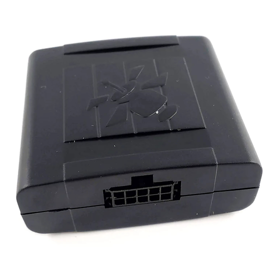
Helios Users Guide Helios Basic 10-pin pin out Function Color Designation Notes Analog / Yellow/Blue Input (+) Digital input is digital Input designated as "Door" by default. Analog can be used for fuel or temperature measurement. See Chapter 4 –... - Page 81 Helios Users Guide The following image shows Helios Basic 10-pin unit. The following image shows Helios Basic 10-pin wire harness. www.starcomgpsglobal.com...
- Page 82 Helios Users Guide The following image shows Helios Basic 10-pin Simulator cable. The following image shows how to connect Helios Basic 10-pin unit to the Simulator. www.starcomgpsglobal.com...
-
Page 83: Helios Advanced 24-Pin Pin Out
Helios Users Guide Helios Advanced 24-pin pin out Function Color Designation Notes Immobilizer Blue Output (-) Install with an and/or Gradual external relay. See Stop Appendix D – Immobilizer and Gradual Stop Door Unlock Gray Output (-) Install with an external relay. - Page 84 Helios Users Guide Speaker (+) / or Violet Audio Hands Free Kit Extra Analog Input connector. In case 3 (-) HFK is not connected, you can cut the connector and use pin 10 as Extra Analog Input Analog 1 Yellow/Blue...
- Page 85 Helios Users Guide The following image shows the pin numbering on the Helios 24-pin J1 connector. www.starcomgpsglobal.com...
- Page 86 Helios Users Guide The following image shows the pin correspondence to different auto components. www.starcomgpsglobal.com...
-
Page 87: Helios Hybrid Connection
(-) and RS232 connector from the rest of the harness. Connect the special RS232 Male to Male cable to RS232 connector on the satellite modem wire harness and to the RS232 connector on the Helios wire harness. Connect the RED Power cable (+) from the satellite modem wire harness to 12 V power source. -
Page 88: Monitoring
Helios Users Guide 7 Monitoring After the unit is installed in the vehicle, you can monitor its status on SGS Online. SGS Online is a web based fleet management application with a flexible event generator which allows setting customizable notifications and alerts. -
Page 89: Home
Helios Users Guide Home The Home section shows recently accessed units and latest site updates. In the Home section, you can find the following additional links: Live status – displays the current status of all live units, as shown in the following image. -
Page 90: Resources
Helios Users Guide Resources The Resources section shows all your units. On the left side, the Resources section features the following tabs: Units – lists the units. Groups – lists the groups of units and helps you create new and modify the existing groups. -
Page 91: Units
Helios Users Guide Units The Units page features the Details area, which arranges the unit information in the following columns: Number – the unit serial number. Clicking on the unit number link will display the Unit Information page, where you can modify the unit information. - Page 92 Use this section to enter the unit Number and Name. In the Cellular Number field, enter the number of the SIM card installed in the unit. In the Unit Type list, select Helios. Use the Terminal list to select the type of terminal connected to the unit.
- Page 93 Helios Users Guide This section features the captions for various fields, like unit inputs, outputs, transmit reasons, etc. which are used throughout the system. The Analog settings help you configure the use of the unit analog inputs, which are usually used for fuel or temperature measurement. For more information, see Appendix F –...
-
Page 94: Groups
Helios Users Guide Groups You can create new and modify the existing groups of units. To create a new group, click New. The Group page opens. In the Name field enter the name of the new group. In the Units list, select the units you want to include in the group and click Add. - Page 95 Helios Users Guide In the Users list, select the users you want to include in the group and click Add. The users will be moved to the Available for list. In the Sharing section, click the respective checkbox, if you want the group to Share Perimeters, Share Events, or Share Drivers.
-
Page 96: Drivers
Helios Users Guide Drivers You can create new and modify the existing drivers. To create a new driver, click New. The Drivers page opens. Here you can enter the new driver information. In the Code field, you can specify the iButton or keypad code of the driver. -
Page 97: Users
Helios Users Guide Users You can create new and modify the existing users. To create a new user, click New. The Users page opens. Here you can enter the new user information and define their access permissions. www.starcomgpsglobal.com... - Page 98 Helios Users Guide Besides entering the user information, you can select the following options: Show all my units on the map –all the user’s units will be displayed on the Map page. If this option is disabled, only the selected unit will be displayed.
- Page 99 Helios Users Guide Force password changing once a month – requires the user to change the password once a month. Allow editing cellular number – enables the user to edit the phone number of the SIM card installed in the unit.
-
Page 100: Perimeters
Helios Users Guide Perimeters You can create new and modify the existing perimeters. To create a new perimeter, click the Button at the bottom left corner of the map to open the Perimeter function To create a new perimeter, click Create New Perimeter. The Create New Perimeter box will change color to Orange. - Page 101 Helios Users Guide The cursor changes to a + and allows you to drag a rectangle over the area you want to demarcate as a perimeter. Once the area is selected, a text box appears. In the Text field, enter the name of the perimeter. From the Color palette, choose a color for the perimeter.
- Page 102 Helios Users Guide Click Save. The new perimeter is saved and appears on the map. www.starcomgpsglobal.com...
-
Page 103: Plans
Helios Users Guide Plans The Plans section enables you to create usage plans and to view plans that already exist. On the left side, the Plans section features the following tabs: Basic – allows to set up basic plans for LCU500 units. Do not use. - Page 104 Helios Users Guide To create a new event type, click New. Enter the name of the event type in the Name field. Leave Day of the week and Time Range as "Changeable", later you will be able to change these settings in the event itself.
- Page 105 Helios Users Guide Set the necessary Value. You can leave the Condition as "Changeable", later you will be able to change it in the event itself. Select the necessary operand in the Operand list, as follows: And – when you create several events, this event and the following one will be performed simultaneously.
- Page 106 Helios Users Guide Enter the cellular number and email address to receive the event notification. If you select the Monitor checkbox, the event will be displayed on the Monitor page (see below) in real time. Click the Add Event button and select the type of the event you want to create from the dropdown list.
- Page 107 Helios Users Guide For example, let’s create an event, which will send an alert when the vehicle goes over a certain speed in a specific location. Go to Types and click New. Enter the event type name and tick the Changeable checkboxes for the Day of the week and Time range.
- Page 108 Helios Users Guide Select Perimeter in the Type list. Select Changeable in the Perimeter list. Select Changeable in the Condition field. Select Transmit in the Operand list. Click Apply. The new event type is saved. Now, go to Events and click New.
- Page 109 Helios Users Guide Enter the name of the event in the Name field. Select the necessary time and date range. Specify the speed limit in the Speed field. Select the necessary perimeter in the Perimeter list. Select Entering in the Condition list.
-
Page 110: Monitor
Helios Users Guide Monitor The Monitor section allows you to select a set of events for a specific unit type and to see them displayed in real time. On the left side, the Monitor section features the following tabs: Monitor – displays the events in real time. - Page 111 Helios Users Guide Select Helios in the Unit Type list. In the Units list, select the units you want to include in the event and click Add. The units will be moved to the Available for list. In the Available reasons list, select the reasons you wish to receive an alert for and click Add.
-
Page 112: Map
Helios Users Guide The Map page displays the location of a single unit, or a group of units. It also shows the unit information and commands. You can select vehicle, group or driver in the dropdown list on the left. - Page 113 Helios Users Guide Once you select the unit, its location will be displayed on the map and its information will appear on the left. The following unit information is displayed: Code – the unit name Location – the address of the last GPS position of the unit Received –...
- Page 114 Helios Users Guide Location – the GPS location of the unit, including: Valid – the date and time of the last location transmission from the unit Speed – the last recorded speed of the unit Mileage – the last recorded mileage of the unit ...
- Page 115 Helios Users Guide The following is an example of the map page showing a Flash Map (regular map). www.starcomgpsglobal.com...
- Page 116 Helios Users Guide Measuring the Distance between Two Points Using the Distance Measurement tool, you can measure the distance between two points on the map. To measure the distance between two points on the map: 1. On the map select the Distance Measurement tool, and move the mouse to the position on the map from which you want to measure the distance to another point.
- Page 117 Helios Users Guide Viewing a Satellite Image You can view a satellite image instead of the map view. To view a satellite image, click on the Satellite button. The Map now shows a satellite image of the area in view.
- Page 118 Helios Users Guide Searching the Map You can search a map using the Search tool. To search a map: 1. Select the Search map tool. A pop-up box appears in which you can enter your search criteria. 2. Enter the City and Street in the respective fields, and click the Search arrow.
-
Page 119: Reports
Helios Users Guide Reports The Reports section allows you to generate different unit reports and to schedule automatically generated reports. On the left side, the Reports section features the following tabs: Instant – allows to generate reports on demand for a single unit or a group of units for a specific time period (date and time range). - Page 120 Helios Users Guide The report includes a map area and tracking details area. The map area shows a map of the area in which the unit is located showing points of movement of the unit. The tracking details area lists the tracking data of the unit.
- Page 121 Helios Users Guide On the bottom of the Map section there is a Play button that enables you to play back the movement of the unit on the map. To save the report, click Save . The report is saved as an *.htm file in a zip file in your default downloads folder.
-
Page 122: Scheduled Reports
Helios Users Guide Scheduled reports To create a scheduled report, in the Reports section, click Schedule. The Schedule page appears Click New. The Report Scheduling page opens. From the Report dropdown list, select the type of report you want to create. - Page 123 Helios Users Guide The Send to field is populated with the default email address for the unit. You can change this address or add additional email addresses, separated by a semicolon. Click Apply. The report schedule is saved and added to the list of scheduled reports.
-
Page 124: Profile
Helios Users Guide Profile The Profile section shows your profile details that were created when you purchased your units. You can view and modify these details as required. To view or modify your profile, click the Profile tab, and modify the information as required. - Page 125 Helios Users Guide Using Map Tooltip Format The Map Tooltip Format field lets you configure the information that will appear in the info window on the Map page when you select a unit. To see all the parameters that can be configured in the Map Tooltip Format field, click on the green question mark located to the right of the field.
-
Page 126: Help
Click on the appropriate tab to access the necessary information. Wiring The wiring section on Help page contains the vehicle wiring database that can be useful when installing Helios in the vehicle. To access the database, press on the Wiring tab. www.starcomgpsglobal.com... - Page 127 Helios Users Guide Scroll through the pages to locate the necessary car model, or use the Search field. Once you found the necessary car model, click on the manufacturer name link to see the wiring details. www.starcomgpsglobal.com...
-
Page 128: Appendix A - Unit Communication In Starcom Systems
Helios Users Guide Appendix A – Unit Communication in Starcom Systems Helios is the mobile component of Starcom’s advanced vehicle tracking and fleet management system. The system uses advanced software algorithms for field tracking of vehicles and provides customers with a selection of real-time information about the tracked vehicle. - Page 129 Helios Users Guide The unit saves all the information that could not be sent in its memory. Once it is able to connect to the network again, it will transmit all the stored data. The device sends encrypted data to the routing server. When the routing receives it, it is decoded and encoded at the same time and sent to all the recipients configured in the system.
-
Page 130: Appendix B - Configuring Mileage
There are 2 ways the unit can receive the mileage readings: by GPS and by Odometer. Initial settings Connect the Helios unit to the computer. In Installer application, go to Helios parameters > General and change the settings as follows: Mileage: Actual mileage reading that you see in the vehicle... - Page 131 Connect the odometer pulse to the Odometer WHITE/BLACK cable on 24-pin Helios wire harness (Pin 20). Initial settings Connect the Helios unit to the computer. In Installer application, go to Helios parameters > General and change the settings as follows: Mileage: 0...
- Page 132 The result (in this case 2,500) will be your new Pulses per KM value. Final settings After this, go back to Installer > Helios parameters > General. Read the data from the unit and change the following parameters: Pulses Per KM: The value that you've calculated (for example 2,500).
-
Page 133: Appendix C - Central Locking System Configuration
Helios enters Armed/Disarmed logic state according to the Logic settings, or specified event settings. 2. The central locking system can control the Helios logic state, changing the Helios logic state from Armed to Disarmed and vice versa each time the vehicle doors are locked/unlocked. Installation Before making any changes to the vehicle wiring, verify which type of locking system is in use. - Page 134 Helios Users Guide If you cannot gain access to the locking engine, you can use external relays and connect to the existing wires that lead to the locking engine. The following image illustrates this connection. www.starcomgpsglobal.com...
- Page 135 Serial Locking This method requires the addition of two external relays. Wire them as follows: Arm/Disarm You can connect the Helios Arm/Disarm function either as a standalone system or in conjunction with the vehicle Arm/Disarm system. Standalone Arming Arming is performed by passive arming, remote control, or transponder.
- Page 136 Connecting to the vehicle Arm/Disarm system Locate the vehicle alarm system and connect the Arm ORANGE/WHITE cable on 24-pin Helios wire harness (Pin 14) to the vehicle alarm system Arm cable with a diode. Also, connect the Disarm PINK cable on 24-pin Helios wire harness (Pin 17) to the vehicle alarm system Disarm cable with a diode.
-
Page 137: Appendix D - Immobilizer And Gradual Stop
When there is no alarm, the Immobilizer/Gradual Stop BLUE cable on 24-pin Helios wire harness (Pin 1) grounds the coil No. 85 (see diagram below) of the external relay. In this case, the relay powers the vehicle starter or fuel pump via pin No. -
Page 138: Appendix E - Connecting A Siren
Helios Users Guide Appendix E – Connecting a Siren Helios can be used to activate the siren. You can add an external siren or use the vehicle horn. NOTE: The vehicle horn can consume large amounts of energy and drain the vehicle battery quickly. -
Page 139: Appendix F - Fuel Management
In heavy trucks that support FMS protocols J1939 and 1708 the Helios unit can monitor the fuel used by the vehicle per each trip. In order setup the Helios unit to monitor fuel used, the following settings should be performed: In Installer, go to Helios Parameters >... - Page 140 Helios Users Guide Analog input Installation The fuel tank in passenger vehicles it is generally located under the back seats. Typically, it has three or five wires: 1. Fuel pump wire – can be identified, when the engine is running, by measuring 12 V on this cable.
- Page 141 WARNING: Do not connect negative voltage to the fuel pump, as this may cause damage. Connect the fuel gauge wire to Analog 1 YELLOW/BLUE cable on 24-pin Helios wire harness (Pin 11). After connecting the analog input to the sensor, you need to configure the correct analog input that will be used for fuel level monitoring and calibrate the analog input to the correct values of the sensor.
- Page 142 Helios Users Guide Calibration When using the Analog input to read fuel the unit and the software should be calibrated to the sensor readings. The calibration can be done in 2 ways: Manual calibration – done by manual reading of the voltage levels of the ...
- Page 143 Helios Users Guide Click . The output will be displayed in the linear parameters. The received "a" and "b" parameters should be entered accordingly in the Unit Information > Captions section on Starcom Online. In order to see the fuel level in percentages in the reports, enter "Fuel" instead of Analog 1 in the Analog 1 field, and enter "%"...
- Page 144 Helios Users Guide Automatic Calibration – the voltage parameters of the fuel readings can be calculated automatically by the system. In order to do so, the vehicle must fuel the tank to 100% and then use the vehicle for a period of 2 additional refuels of 100%.
-
Page 145: Appendix G - Can Bus Connection
High wire, the low speed pulses – the CAN Low wire. Installation Connect the CAN High wire to CAN High BLACK/GRAY cable on 24-pin Helios wire harness (Pin 12). Connect the CAN Low wire to CAN Low GRAY/BLUE cable on 24-pin Helios wire harness (Pin 24). - Page 146 Helios Users Guide Configuration After connecting the CAN wires, connect to the Helios unit with a computer and update the vehicle model from the existing database. In Installer, go to Technical > Helios Canbus. Press the Update Database button Select the vehicle type in the Type dropdown list. For trucks choose FMS.
- Page 147 Helios Users Guide Adding a new vehicle to the database When Helios is installed in the vehicle that is not present in the database, you need to create it by identifying the CAN bus signals and manually adding the vehicle to the database.
- Page 148 Click the Update Database button to save the new information to Starcom CAN Bus Database. Open Helios Parameters > Hardware. In the Canbus Vehicle section, select your vehicle from the list and click Send button to send the definitions to the unit.
- Page 149 Helios Users Guide In the Unit Status window you will see a new RPM tab. Request status several times to see that the RPM data is updated, which means that Helios is receiving the readings from CAN Bus. OBD II Connection This direct connection to the vehicle’s computer through the on-board...
- Page 150 Testing After the unit was properly installed, you should test the connection. Open the Installer Application, go to Technical > Helios Canbus, select OBD-II as the vehicle type, and click Connect. If everything is correct, you will see the information that the unit can retrieve from the vehicle, as shown in the following image.
- Page 151 Helios Users Guide Finally, use the Unit Status window to send a Mileage-Set KM command to the unit with the current vehicle’s mileage. www.starcomgpsglobal.com...
-
Page 152: Appendix H - Using Keypad With Rf Relay
You can use an external RF relay (up to 3 units), which will be activated by a keypad code, to perform the immobilizer functions. Configuration In Installer application, go to Helios Parameters > Outputs, enable the Use keypad RF instead of Immobilizer output option. Select Immobilizer On when Armed, if you’re using a Normally Closed relay. - Page 153 Helios Users Guide In Installer, go to Helios Parameters > Driver IDs and configure the codes in the following way. The first 3 code fields are reserved exclusively for the relay units (up to 3). If you’re using one relay unit, enter its number in the first field and enter 0000 in the following two fields.
- Page 154 Helios Users Guide Installation The following image shows the relay and socket with cables. The following diagram illustrates the relay cables connection. 1. Relay connection 1 2. Relay connection 2 3. Main power 12 V (+) (usually RED) 4. Data (GRAY) – NOT IN USE 5.
-
Page 155: Appendix I - Cellular Phone Commands
Helios Users Guide Appendix I – Cellular Phone Commands You can use a cellular phone to send commands to Helios. On Starcom Online, go to Unit Information and make sure that the unit is configured to receive commands from a cellular phone. -
Page 156: Appendix J - Contacts
Helios Users Guide Appendix J – Contacts For more information about Starcom Systems Company and products, please visit: http://www.starcomgpsglobal.com For more information about Starcom GPS Global Solutions products, please visit: https://trello.com/b/NjmQefGw/product-info-clients Support Should you have any questions regarding our system, please contact SGS technical support.
Need help?
Do you have a question about the Helios and is the answer not in the manual?
Questions and answers