Table of Contents
Advertisement
Quick Links
BP7513 Volta CF590
1/5/16
READ AND SAVE THESE INSTRUCTIONS
Ceiling Fan Owner's Manual
CF590BQ00 -
CF590PT00 -
CF590SW00 -
Emerson Electric Customer Service - 8 a.m. - 6 p.m., Eastern, Monday-Friday
Part No. F40BP75130000
Revision: 151217
10:52 AM
Page 1
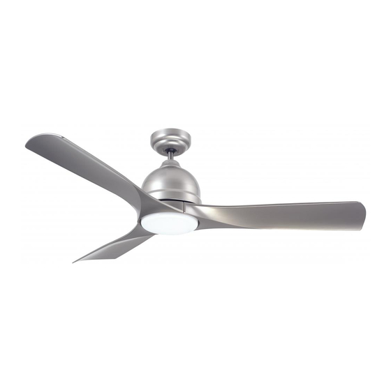
VOLTA
54" Wet Location
Model Numbers
Net Weight:
Questions, problems, missing parts: Before returning to the store call
1-800-654-3545
www.emersonfans.com
™
Barbeque Black
Platinum
Satin White
??.?
Lbs.
• Español - página 33
• Français - page 65
Form No. BP7513
U.L. Model No.: CF590
Advertisement
Table of Contents

Related Manuals for Emerson VOLTA CF590BQ00


Summary of Contents for Emerson VOLTA CF590BQ00
- Page 1 ??.? Net Weight: Lbs. Questions, problems, missing parts: Before returning to the store call Emerson Electric Customer Service - 8 a.m. - 6 p.m., Eastern, Monday-Friday • Español - página 33 1-800-654-3545 • Français - page 65 Part No. F40BP75130000 Form No.
-
Page 2: Table Of Contents
Electrical Codes. Use the National Electrical Code if accessories not designated for use with this product Local Codes do not exist. The ceiling fan must be by Emerson could result in personal injury or property grounded as a precaution against possible electrical damage. -
Page 3: Unpacking Instructions
Emerson Electric Co. Substitution of parts or Acrylic Shade accessories not designated for use with this product No-Light Plate by Emerson Electric Co. could result in personal injury or property damage. Remote Control, SR400 Receiver Open carton containing fan. Remove top half of styrofoam unit. -
Page 4: Tools Needed For Assembly
One Phillips head screwdriver One stepladder allows you to regulate your ceiling fan speed and light One 1/4” blade screwdriver One wire stripper control. This Emerson Ceiling Fan may be used with the Materials following accessory (purchased separately): SW605 Wall Control. -
Page 5: Ceiling Fan Assembly
BP7513 Volta CF590 1/5/16 10:52 AM Page 5 3. Ceiling Fan Assembly MOTOR HUB Remove the three rubber shipping spacers from the motor hub of the fan motor assembly before installation RUBBER of blade assemblies (Figure 1). SHIPPING SPACERS (3) Discard the three rubber shipping spacers. - Page 6 BP7513 Volta CF590 1/5/16 10:52 AM Page 6 3. Ceiling Fan Assembly (Continued) Carefully turn the partially assembled ceiling fan right PARTIALLY ASSEMBLED CEILING FAN side up and position the fan on the styrofoam in preparation for final assembly (Figure 4). STYROFOAM Figure 4 GREEN GROUND WIRE...
- Page 7 BP7513 Volta CF590 1/5/16 10:52 AM Page 7 3. Ceiling Fan Assembly (Continued) Loosen the two setscrews in the motor coupler for installation of the downrod (Figure 7). Seat the downrod in the motor coupler (Figure 7). 4.5" DOWNROD Rotate and align the downrod holes with all the holes in the motor coupler (Figure 7).
- Page 8 BP7513 Volta CF590 1/5/16 10:52 AM Page 8 3. Ceiling Fan Assembly (Continued) 3.10 DOWNROD Place the ceiling cover over the downrod (Figure 10). CEILING Be sure that the ceiling cover and the coupling cover COVER are both oriented correctly (Figure 10). Figure 10 3.11 Route the three 80”...
-
Page 9: How To Hang Your Ceiling Fan
BP7513 Volta CF590 1/5/16 10:52 AM Page 9 4. How to Hang Your Ceiling Fan CEILING WARNING The fan must be hung with at least 7' of clearance from floor to blades (Figure 13). LEAST FLOOR Figure 13 WARNING The outlet box and joist must be securely mounted and capable of supporting at least 50 lbs. - Page 10 BP7513 Volta CF590 1/5/16 10:52 AM Page 10 4. How to Hang Your Ceiling Fan (Continued) NOTE: CEILING COVER, SUPPL Y WIRES AND FAN WIRES Carefully lift the partially assembled ceiling fan and seat OMITTED FOR CLARITY. the hanger ball/downrod assembly on the hanger bracket that was just attached to the outlet box (Figure 15).
-
Page 11: Led Light Kit Assembly
BP7513 Volta CF590 1/5/16 10:52 AM Page 11 5. Light Kit Assembly NOTE: If installing Ceiling Fan without the Light Kit Assembly, Skip to Section 6. Optional Installation of No-Light Plate Assembly. Engage the white wire connector from the Fan Motor Assembly to the Light Kit Assembly white wire connector until you hear a snap (Figure 16). - Page 12 BP7513 Volta CF590 1/5/16 10:52 AM Page 12 5. Light Kit Assembly (Continued) Remove one of the three Pan Head Screws with LOOSEN THE TWO PAN HEAD Lockwashers in the Light Kit Adapter and loosen the SCREWS WITH LOCKWASHERS remaining two screws (Figure 18). Retain the screw and lockwasher for future use.
- Page 13 BP7513 Volta CF590 1/5/16 10:52 AM Page 13 6. Optional Installation of No-Light Plate Assembly NOTE: To use the No-Light Plate Assembly, the Light Kit Assembly MUST NOT Be Installed, or Light Kit Assembly MUST Be Removed. WARNING Turning off wall switch is not sufficient. To avoid LIGHT KIT possible electrical shock, be sure electricity is turned ADAPTER/...
-
Page 14: No-Light Plate Assembly
BP7513 Volta CF590 1/5/16 10:52 AM Page 14 6. No-Light Plate Assembly (Continued) Disengage the white wire connector from the fan motor assembly to the Light Kit Assembly white wire connector (Figure 24). Retain the Light Kit Assembly in a safe place for possible future reinstallation. -
Page 15: How To Wire Your Ceiling Fan
Emerson Electric Co. Substitution of parts or accessories not designated for use with this product by Emerson Electric Co. could result in personal injury or property damage. RECEIVER WHITE WIRE... - Page 16 BP7513 Volta CF590 1/5/16 10:52 AM Page 16 7. How to Wire Your Ceiling Fan (Continued) Securely connect the receiver black wire (AC in L) to the supply black wire (hot) using the wire connector (supplied in parts bag) (Figure 28). SUPPLY BLACK WIRE (Hot) RECEIVER BLACK WIRE...
- Page 17 BP7513 Volta CF590 1/5/16 10:52 AM Page 17 7. How to Wire Your Ceiling Fan (Continued) Securely connect the receiver blue wire (TO LIGHT) to the fan motor blue wire using the wire connector (supplied in parts bag) (Figure 31). RECEIVER BLUE WIRE (TO LIGHT)
- Page 18 BP7513 Volta CF590 1/5/16 10:52 AM Page 18 7. How to Wire Your Ceiling Fan (Continued) Lift the ceiling cover up to the threaded studs and turn until studs protrude through the holes in the ceiling cover (Figure 34). CEILING COVER Secure the ceiling cover in place by sliding lockwashers over the threaded studs and installing the two knurled...
-
Page 19: Led Light Kit Replacement
BP7513 Volta CF590 1/5/16 10:52 AM Page 19 8. Light Kit Assembly Replacement Repair of the Light Kit can be Accomplished By; 1) Replacing the Entire Light Kit Assembly or; 2) Replacing the Driver or Array Components Individually. WARNING METHOD 1- REPLACING THE ENTIRE LIGHT Turning off wall switch is not sufficient. - Page 20 BP7513 Volta CF590 1/5/16 10:52 AM Page 20 8. Light Kit Assembly Replacement (Continued) Disengage the fan motor assembly black wire connector from the black wire connector of the new Light Kit FAN MOTOR Assembly (Figure 38). ASSEMBLY BLACK WIRE Disengage the fan motor assembly white wire connector CONNECTOR from the white wire connector of the new Light Kit...
- Page 21 BP7513 Volta CF590 1/5/16 10:52 AM Page 21 8. Light Kit Assembly Replacement (Continued) 8.10 LIGHT KIT ASSEMBLY LIGHT KIT ASSEMBLY Remove the paper backing from the adhesive foam tape DRIVER TWO PIN ARRAY CONNECTOR on the bottom of the new Light Kit Assembly Driver. CONNECTOR Place the new Light Kit Assembly Driver into the assembly, aligning it directly where the old Driver had...
- Page 22 BP7513 Volta CF590 1/5/16 10:52 AM Page 22 8. Light Kit Assembly Replacement (Continued) 8.14 PLASTIC PHILLIPS HEAD SCREWS (3) Unscrew the three plastic Phillips head screws securing the Light Kit Assembly Array to the Light Kit Assembly LIGHT KIT (Figure 43).
-
Page 23: Reverse Switch Operation
BP7513 Volta CF590 1/5/16 10:52 AM Page 23 8. Light Kit Assembly Replacement (Continued) 8.17 Reconnect the fan motor assembly black wire connector into the black wire connector of the Light Kit Assembly FAN MOTOR (Figure 46). The connection is complete when you hear ASSEMBLY BLACK WIRE a soft click. -
Page 24: Remote Control Procedures
10.2 speed and light intensity. Preset Memory Feature: Your Emerson receiver is The remote control transmitter is powered by two AAA equipped with a preset memory feature. If the AC alkaline batteries (included). To prevent possible... -
Page 25: Setting The Operating Frequency Of Remote Control
BP7513 Volta CF590 1/5/16 10:52 AM Page 25 11. Setting Operating Frequency of Remote Control WARNING POWER INDICATOR Fan installation must be completed, including the LIGHT installation of the fan blades, before testing the remote control. BUTTON 11.1 Your remote control has code switches which must be HIGH TO LOW set in one of 32 possible code combinations BUTTONS... -
Page 26: Maintenance
Emerson Electric Co. Substitution of parts or accessories not designated for use with this product WARNING by Emerson Electric Co. could result in personal injury or property damage. The use of any other control not specifically approved for this fan could result in fire, shock and personal injury. -
Page 27: Troubleshooting
BP7513 Volta CF590 1/5/16 10:52 AM Page 27 15. Troubleshooting WARNING FOR YOUR OWN SAFETY TURN OFF POWER AT FUSE BOX OR CIRCUIT BREAKER BEFORE TROUBLESHOOTING YOUR FAN. TROUBLE PROBABLE CAUSE SUGGESTED REMEDY 1. Loose power line connections to the fan, 1. -
Page 28: Repair Parts
BP7513 Volta CF590 1/5/16 10:52 AM Page 28 16. Repair Parts PARTS BAG U.L. Model No.: CF590... - Page 29 BP7513 Volta CF590 1/5/16 10:52 AM Page 29 16. Repair Parts Listing Model Numbers Description CF590BQ00 CF590PT00 CF590SW00 Hanger Ball Assembly, 761655-19 761655-101 761655-97 Consisting of: Hanger Bracket — — — Hanger Ball — — — 4.5” Downrod — — —...
- Page 30 BP7513 Volta CF590 1/5/16 10:52 AM Page 30 INSTRUCTION TO THE USER (if device contains a digital device) This equipment has been tested and found to comply with the limits for a class B digital device, pursuant to part 15 of the FCC Rules. These limits are designed to provide reasonable protection against harmful interference in a residential installation.
-
Page 31: Ceiling Fan Limited Warranty
Manual or other instructions provided by Emerson to you with the Emerson Ceiling Fan). LED drivers are covered for a period of three (3) years, and any LED array is covered for a period of five (5) years. All other components and accessories of the Emerson Ceiling Fan are covered by this limited warranty for a period of one (1) year. All warranty periods begin on the date of original retail purchase. - Page 32 You should record this data above and keep it in a safe place for future use. Air Comfort Products DIVISION OF EMERSON ELECTRIC CO. 8100 W. Florissant • St. Louis, MO 63136 Questions, problems, missing parts: Before returning to the store call Emerson Electric Customer Service 8 a.m.
Need help?
Do you have a question about the VOLTA CF590BQ00 and is the answer not in the manual?
Questions and answers