Table of Contents
Advertisement
Quick Links
READ AND SAVE THESE INSTRUCTIONS
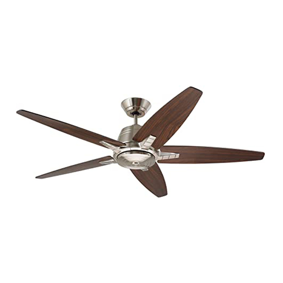
56" Ceiling Fan Owner's Manual
CF500AP00 -
CF500BS00 -
CF500ORB00 -
Questions, problems, missing parts: Before returning to the store call
Part No. F40BP75190000
Revision: 161103
EUCLID
Model Numbers
Antique Pewter
Brushed Steel
Oil Rubbed Bronze
22.4
Net Weight:
Emerson Electric Customer Service
8 a.m. - 6 p.m., Eastern, Monday-Friday
1-800-654-3545
www.emersonfans.com
™
Lbs.
4
3
2
1
0
• Español - página 23
• Français - page 45
Form No. BP7519
U.L. Model No.: CF500
Advertisement
Table of Contents

Related Manuals for Emerson EUCLID CF500AP00


Summary of Contents for Emerson EUCLID CF500AP00
- Page 1 Oil Rubbed Bronze 22.4 Net Weight: Lbs. Questions, problems, missing parts: Before returning to the store call Emerson Electric Customer Service 8 a.m. - 6 p.m., Eastern, Monday-Friday • Español - página 23 • Français - page 45 1-800-654-3545 Part No. F40BP75190000 Form No.
-
Page 2: Table Of Contents
Local Codes do not exist. The ceiling fan must be specifically for use this product by Emerson Electric Co. grounded as a precaution against possible electrical Substitution of parts or accessories not designated for shock. -
Page 3: Unpacking Instructions
Switch Housing Adapter Co. Substitution of parts or accessories not designated Switch Housing Cover for use with this product by Emerson Electric Co. could result in personal injury or property damage. Fan Blades Check to see that you have received the following parts: NOTE: If you are uncertain of part description, refer to exploded view illustration. -
Page 4: Electrical Requirements
This Manual Is Designed to Make it as Easy as Possible for You to Assemble, Install, Operate and Maintain Your Ceiling Fan Tools Needed for Assembly Your Emerson Ceiling Fan comes supplied with a Fan Wall Control. This system allows you to regulate your ceiling fan One Phillips head screwdriver One stepladder speed. -
Page 5: Ceiling Fan Assembly
3. Ceiling Fan Assembly NOTE: Intermixing blades and flanges between fans can cause excessive wobble. Keep blades and flanges #10-24 x 9/32" WASHER in original sets of five. HEAD SCREW Place the fan blade on the fan blade flange (Figure 1). Tighten the #10-24 x 9/32”... - Page 6 #8-32 x 5/16" FLAT HEAD SCREWS (3) A spare #8-32 x 5/16” flat head screw supplied in parts bag, SWITCH HOUSING ADAPTER if needed. The finial may be removed for use with an Emerson light kit. Figure 4 U.L. Model No.: CF500...
- Page 7 3. Ceiling Fan Assembly (Continued) Carefully turn the partially assembled fan right side up and GREEN GROUND WIRE place on the styrofoam carton, in preparation for final installation. Remove the hanger ball by loosening the Phillips head set screw in the hanger ball until the ball falls freely down the 4.5"...
- Page 8 3. Ceiling Fan Assembly (Continued) Align the clevis pin holes in the downrod with the holes in the motor coupler. Install the clevis pin and secure with the hairpin clip HAIRPIN (Figure 8). CLIP MOTOR CLEVIS COUPLING The clevis pin must go through the holes in the motor coupler.
- Page 9 3. Ceiling Fan Assembly (Continued) 3.11 Route the two motor leads through the hanger ball 4.5" DOWNROD (Figure 11). HANGER PHILLIPS HEAD Reinstall the hanger ball on the downrod as follows: BALL SET SCREW Position the pin through the two holes in the downrod and align the hanger ball so the pin is captured in the groove in the top of the hanger ball (Figure 11).
- Page 10 WARNING CEILING The fan must be hung with at least 7' of clearance from floor to blades (Figure 13). LEAST FLOOR Figure 13 WARNING The outlet box and joist must be securely mounted and capable of supporting at least 50 lbs. Use only a U.L. outlet box listed as “Acceptable for Fan Support of 22.7 kg.
-
Page 11: How To Hang Your Ceiling Fan
4. How to Hang Your Ceiling Fan (Continued) Carefully lift the fan and seat the hanger ball/ NOTE: CEILING COVER, SUPPL Y WIRES AND FAN WIRES downrod assembly on the hanger bracket that was just OMITTED FOR CLARITY. attached to the outlet box (Figure 15). Be sure the groove in the ball is engaged with the anti- rotation tab on the hanger bracket (Figure 15). -
Page 12: How To Wire Your Ceiling Fan
Emerson Electric Co. Substitution of parts or accessories not designated for use with this product by Emerson Electric Co. could result in personal injury or property damage. Securely connect the fan motor white wire to the supply white (neutral) wire using wire connector (supplied) (Figure 17). -
Page 13: How To Wire Your Ceiling Fan
5. How to Wire Your Ceiling Fan (Continued) Securely connect the fan motor black wire and blue wires to the supply black (hot) wire using wire connector (supplied) (Figure 18). F AN MOTOR BLACK WIRE SUPPLY BLACK (HOT) LISTED WIRE CONNECTOR F AN MOTOR BLUE WIRE... - Page 14 5. How to Wire Your Ceiling Fan (Continued) Screw the two threaded studs (supplied) into the tapped holes in the hanger bracket (Figure 20). THREADED STUDS (2) Figure 20 Lift the ceiling cover up to the threaded studs and turn until studs protrude through the holes in the ceiling cover (Figure 21).
-
Page 15: Installing The Wall Control
6. Installing the Wall Control WARNING Turning off wall switch is not sufficient. To avoid possible electrical shock, be sure electricity is turned off at the main fuse box before wiring. All wiring must be in accordance with National and Local codes and the ceiling fan must be properly grounded as a precaution against possible electrical shock. -
Page 16: Using Your Ceiling Fan
6. Installing the Wall Control (Continued) Attach the SW46W Fan Control to the wall outlet box with WALL OUTLET BOX two 6-32 x 3/4” screws (provided with control). SW46 F AN CONTROL Position the faceplate (provided with control) onto the speed control. -
Page 17: Maintenance
Emerson Electric Co. Substitution of parts or accessories not designated • Slope Ceiling Kit for use with this product by Emerson Electric Co. could result in personal injury or property damage. • Ceiling Fan Light Kit... -
Page 18: Repair Parts
10. Repair Parts PARTS BAG U.L. Model No.: CF500... - Page 19 10. Repair Parts Listing Model Numbers Description CF500AP00 CF500BS00 CF500ORB00 Hanger Ball Assembly, Consisting of: 761655-34 761655-17 761655-32 Hanger Bracket (1) — — — Hanger Ball (1) — — — 4.5” Downrod (1) — — — Parts Bag Containing: 764813-BLX 764813-CRM 764813-BLX Wire Connectors (4)
-
Page 20: Troubleshooting
11. Troubleshooting WARNING FOR YOUR OWN SAFETY TURN OFF POWER AT FUSE BOX OR CIRCUIT BREAKER BEFORE TROUBLESHOOTING YOUR FAN. TROUBLE PROBABLE CAUSE SUGGESTED REMEDY 1. Fan will not start. 1. Fuse or circuit breaker blown. 1. Check main and branch circuit fuses or circuit breakers. WARNING Make sure main power is turned OFF. -
Page 21: Ceiling Fan Limited Warranty
Emerson Ceiling Fan. Once we have processed your return authorization request, we will provide you with a postage paid return label which should be affixed to the Emerson Ceiling Fan package you ship to the address listed at the end of this limited warranty. The return label will be sent to the mailing address you provide to us by phone. - Page 22 You should record this data above and keep it in a safe place for future use. Air Comfort Products DIVISION OF EmErSON ElEctrIc cO. 8100 W. Florissant • St. louis, mO 63136 Questions, problems, missing parts: Before returning to the store call Emerson Electric Customer Service 8 a.m.
Need help?
Do you have a question about the EUCLID CF500AP00 and is the answer not in the manual?
Questions and answers