Table of Contents
Advertisement
BP7511-1 CF5200 Penbrooke Select Eco.qxp_ BP7511 2/8/16 12:02 PM Page 1
READ AND SAVE THESE INSTRUCTIONS
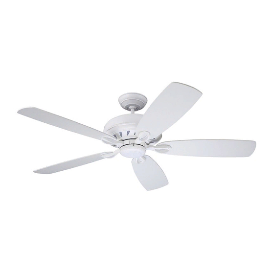
44", 54", 60" or 72"
Fan Blades Not Included
PENBROOKE SELECT ECO
CF5200BS00 -
CF5200ORB00 -
CF5200SW00 -
Ceiling Fan Owner's Manual
Model Numbers
Net Weight:
1-800-654-3545
www.emersonfans.com
Brushed Steel
Oil Rubbed Bronze
Satin White
21.2
Lbs.
Advertisement
Table of Contents

Related Manuals for Emerson CF5200BS00


Summary of Contents for Emerson CF5200BS00
- Page 1 BP7511-1 CF5200 Penbrooke Select Eco.qxp_ BP7511 2/8/16 12:02 PM Page 1 READ AND SAVE THESE INSTRUCTIONS 44”, 54”, 60” or 72” Fan Blades Not Included PENBROOKE SELECT ECO Ceiling Fan Owner's Manual Model Numbers CF5200BS00 - Brushed Steel CF5200ORB00 - Oil Rubbed Bronze CF5200SW00 - Satin White 21.2 Net Weight: Lbs.
-
Page 2: Table Of Contents
4. Do not operate reversing switch until fan blades have Electric Co. Substitution of parts or accessories not come to a complete stop. designated for use with this product by Emerson could Additional Safety Instructions for Installation result in personal injury or property damage. -
Page 3: Unpacking Instructions
Emerson Electric Co. Substitution of parts or accessories not designated for use with this product by Emerson Electric Co. could result in personal injury or property damage. NOTE: If you are uncertain of part description, refer to Check to see that you have received the following parts: exploded view illustration. -
Page 4: Electrical Requirements
One 1/4” Blade Screwdriver One Wire Stripper Materials This Emerson Ceiling Fan may be used with the following accessories: SR600 Remote Control. WARNING Wiring outlet box and box connectors must be of type required by the local code. -
Page 5: Ceiling Fan Assembly
BP7511-1 CF5200 Penbrooke Select Eco.qxp_ BP7511 2/8/16 12:02 PM Page 5 3. Ceiling Fan Assembly GREEN GROUND WIRE Remove the hanger ball by loosening the Phillips head set screw in the hanger ball until the ball falls freely down the downrod (Figure 1). - Page 6 BP7511-1 CF5200 Penbrooke Select Eco.qxp_ BP7511 2/8/16 12:02 PM Page 6 3. Ceiling Fan Assembly (Continued) Align the clevis pin holes in the downrod with the holes in the motor coupler. HAIRPIN CLIP Install the clevis pin and secure with the hairpin clip CLEVIS (Figure 4).
- Page 7 BP7511-1 CF5200 Penbrooke Select Eco.qxp_ BP7511 2/8/16 12:02 PM Page 7 3. Ceiling Fan Assembly (Continued) Route the two motor leads through the hanger ball HANGER BALL (Figure 7). 4.5" DOWNROD Reinstall the hanger ball on the downrod as follows: PHILLIPS HEAD Position the pin through the two holes in the downrod and SET SCREW...
- Page 8 BP7511-1 CF5200 Penbrooke Select Eco.qxp_ BP7511 2/8/16 12:02 PM Page 8 3. Ceiling Fan Assembly (Continued) REMOVE & DISCARD Carefully turn the partially assembled ceiling fan upside PARTIALLY 5 RUBBER SHIPPING ASSEMBLED SPACERS & 10 SCREWS down, place the ceiling fan onto the two carton styrofoam CEILING FAN pieces, in preparation for final assembly (Figure 9).
- Page 9 BP7511-1 CF5200 Penbrooke Select Eco.qxp_ BP7511 2/8/16 12:02 PM Page 9 3. Ceiling Fan Assembly (Continued) 3.11 #10-32 x 5/8" OVAL HEAD SCREW Loosely attach one blade/flange assembly to the motor (2 per blade/flange) hub by securing the two #10-32 x 5/8” oval head screws (supplied in parts bag) (Figure 11).
-
Page 10: How To Hang Your Ceiling Fan
BP7511-1 CF5200 Penbrooke Select Eco.qxp_ BP7511 2/8/16 12:02 PM Page 10 4. How to Hang Your Ceiling Fan WARNING CEILING The fan must be hung with at least 7' of clearance from floor to blades (Figure 12). AT LEAST FLOOR Figure 12 WARNING The outlet box and joist must be securely mounted and... - Page 11 BP7511-1 CF5200 Penbrooke Select Eco.qxp_ BP7511 2/8/16 12:02 PM Page 11 4. How to Hang Your Ceiling Fan (Continued) NOTE: CEILING COVER, SUPPL Y WIRES AND FAN WIRES OMITTED FOR CLARITY. Carefully lift the fan and seat the hanger ball/ downrod assembly on the hanger bracket that was just attached to the outlet box (Figure 14).
-
Page 12: How To Wire Your Ceiling Fan
Emerson Electric Co. Substitution of parts or accessories not designated for use with this product by Emerson Electric Co. could result in personal injury or property damage. Securely connect the fan motor white wire to the supply... - Page 13 BP7511-1 CF5200 Penbrooke Select Eco.qxp_ BP7511 2/8/16 12:02 PM Page 13 5. How to Wire Your Ceiling Fan (Continued) Securely connect the fan motor black wire to the supply black (hot) wire using wire connector (supplied) (Figure 17). SUPPLY BLACK (HOT) LISTED WIRE CONNECTOR...
-
Page 14: How To Wire Your Ceiling Fan
BP7511-1 CF5200 Penbrooke Select Eco.qxp_ BP7511 2/8/16 12:02 PM Page 14 5. How to Wire Your Ceiling Fan (Continued) Screw the two threaded studs (supplied) into the tapped holes in the hanger bracket (Figure 19). THREADED STUDS (2) Figure 19 Lift the ceiling cover up to the threaded studs and turn until studs protrude through the holes in the ceiling cover (Figure 20). -
Page 15: Final Assembly
BP7511-1 CF5200 Penbrooke Select Eco.qxp_ BP7511 2/8/16 12:02 PM Page 15 6. Final Assembly Remove one #6-32 x 3/8” round head screw with lockwasher from the motor hub and retain for later use (Figure 21). Loosen the other two #6-32 x 3/8” round head screws with lockwashers on the motor hub for the installation of the switch housing adapter (Figure 21). - Page 16 BP7511-1 CF5200 Penbrooke Select Eco.qxp_ BP7511 2/8/16 12:02 PM Page 16 6. Final Assembly (Continued) The switch housing assembly connector and the motor hub connector are keyed and color-coded and must be mated correctly (same color-to-color) before they can be engaged.
-
Page 17: Wall Control Procedures
Code switches in the transmitter and receiver may be set in 32 different positions. If your fan and light go on and off Your Emerson Ceiling Fan/Light Control consists of wall without using your control, you may be getting interference... -
Page 18: Wall Control Installation
BP7511-1 CF5200 Penbrooke Select Eco.qxp_ BP7511 2/8/16 12:02 PM Page 18 8. Wall Control Installation WARNING Turning off wall switch is not sufficient. To avoid possible electrical shock, be sure electricity is turned off at the main fuse or circuit breaker box before wiring. All wiring must be in accordance with National and Local codes and the ceiling fan must be properly grounded as a precaution against possible electrical shock. - Page 19 BP7511-1 CF5200 Penbrooke Select Eco.qxp_ BP7511 2/8/16 12:02 PM Page 19 8. Wall Control Installation (Continued) SW605 FAN/LIGHT SCREWS (2) WALL BOX WALL CONTROL Before installing wall control, place wall control in “OFF” mode by pushing “ON/OFF” switch to the “OFF” position. Connect one black wire of wall control to the “hot”...
- Page 20 BP7511-1 CF5200 Penbrooke Select Eco.qxp_ BP7511 2/8/16 12:02 PM Page 20 8. Wall Control Installation (Continued) 3-WAY INSTALLATION (One fan controlled by two different wall controls) (See Figures 29 and 30). SW605 FAN/LIGHT WARNING WALL CONTROL Turning off wall switch is not sufficient. To avoid possible electrical shock, be sure electricity is turned off at the BLACK main fuse or circuit breaker box before wiring.
-
Page 21: Wall Control Installation
BP7511-1 CF5200 Penbrooke Select Eco.qxp_ BP7511 2/8/16 12:02 PM Page 21 8. Wall Control Installation (Continued) 3-WAY WIRING DIAGRAM: STANDARD WIRING FOR EXISTING NEW CONSTRUCTION 3-WAY CONTROLS NOTE: Retrofit 3-way installations are likely to include two traveler wires between the two wall boxes. In new construction, only one traveler wire Is required (See Figure 30). -
Page 22: Programming The Receiver Operating Frequency & High Speed Conditioning Of Fan Control
BP7511-1 CF5200 Penbrooke Select Eco.qxp_ BP7511 2/8/16 12:02 PM Page 22 9. Programming the Receiver Operating Frequency & High Speed Conditioning of Fan Control -- Important - Read This Section Carefully and Follow the High Speed Conditioning Instructions Closely -- PROGRAMMING THE RECEIVER OPERATING FREQUENCY &... -
Page 23: Using Your Ceiling Fan
BP7511-1 CF5200 Penbrooke Select Eco.qxp_ BP7511 2/8/16 12:02 PM Page 23 10. Using Your Ceiling Fan WARNING Fan installation must be completed, including the installation of the fan blades, before testing the remote control. POWER INDICATOR Your wall control has full control of your fan and light LIGHT 10.1 (Figure 31). -
Page 24: Optional Al100 Accent Light Installation
BP7511-1 CF5200 Penbrooke Select Eco.qxp_ BP7511 2/8/16 12:02 PM Page 24 11. Optional AL100 Accent Light Installation 11.1 CAUTION: To reduce the risk of electric shock, disconnect the electrical supply circuit to the fan before installing light kit assembly. AL100 ACCENT AL100 ACCENT LIGHT HARNESS Position the AL100 accent light so that the opening of the... -
Page 25: Maintenance
Emerson Electric · Downrod Extension Kits Co. Substitution of parts or accessories not designated for use with this product by Emerson Electric Co. could WARNING result in personal injury or property damage. The use of any other control not specifically approved for this fan could result in fire, shock and personal injury. -
Page 26: Repair Parts
BP7511-1 CF5200 Penbrooke Select Eco.qxp_ BP7511 2/8/16 12:02 PM Page 26 15. Repair Parts PARTS BAG (Not Supplied) - Page 27 BP7511-1 CF5200 Penbrooke Select Eco.qxp_ BP7511 2/8/16 12:02 PM Page 27 15. Repair Parts Listing Model Numbers Description CF5200BS00 CF5200ORB00 CF5200SW00 Before discarding packaging material, be certain all parts have been removed. HOW TO ORDER REPAIR PARTS WHEN ORDERING REPAIR PARTS, ALWAYS GIVE THE FOLLOWING INFORMATION: •...
-
Page 28: Troubleshooting
BP7511-1 CF5200 Penbrooke Select Eco.qxp_ BP7511 2/8/16 12:02 PM Page 28 16. Troubleshooting WARNING: FOR YOUR OWN SAFETY TURN OFF POWER AT FUSE BOX OR CIRCUIT BREAKER BEFORE TROUBLESHOOTING YOUR FAN. TROUBLE PROBABLE CAUSE SUGGESTED REMEDY 1. Fan will not start. 1. -
Page 29: Ceiling Fan Limited Warranty
BP7511-1 CF5200 Penbrooke Select Eco.qxp_ BP7511 2/8/16 12:02 PM Page 29 Emerson Air Comfort Ceiling Fan Limited Warranty What The Limited Warranty Covers: "Emerson" "we" "us" "you" "your" "Emerson Ceiling Fan" What The Period Of Coverage Is: No Other Express or Implied Warranty Applies:... - Page 30 BP7511-1 CF5200 Penbrooke Select Eco.qxp_ BP7511 2/8/16 12:02 PM Page 30 Air Comfort Products DIVISION OF EmErSON ElEctrIc cO. 8100 W. Florissant • St. louis, mO 63136 1-800-654-3545 www.emersonfans.com...
Need help?
Do you have a question about the CF5200BS00 and is the answer not in the manual?
Questions and answers