kozy heat MPS-30 Minneapolis Installation And Operation Manual
Direct vent fireplace insert
Hide thumbs
Also See for MPS-30 Minneapolis:
- Installation and operation manual (38 pages) ,
- Installation manual (40 pages)
Table of Contents
Advertisement
Quality Fireplaces for Life
DIRECT VENT FIREPLACE INSERT
WARNING: This product must be installed by a licensed plumber or gas fitter when installed in the
commonwealth of Massachusetts.
This appliance may be installed in an aftermarket permanently located, manufactured (mobile) home, where not prohibited by local codes.
A manufactured home (USA only) or mobile home OEM installation must conform with the Manufactured Home Construction and Safety
Standard, Title 24 CFR, Part 3280, or when such a standard is not applicable, the Standard for Manufactured Home Installations, ANSI/NCSBCS A225.1,
or Standard for Gas Equipped Recreational Vehicles and Mobile Housing, CSA Z240.4
WARNING: If the information in these instructions are not followed exactly, a fire or explosion may
result, causing property damage, personal injury or loss of life.
◙
Do not store or use gasoline or other flammable vapors and liquids in the vicinity of this or any other
appliance.
IF YOU SMELL GAS:
◙ Do not light any appliance.
◙ Do not touch any electrical switch: do not use any phone in your building.
◙ Immediately call gas supplier from a neighbors phone. Follow the gas supplier instructions.
◙ If you cannot reach your gas supplier, call the fire department.
◙ Installation and service must be performed by a qualified installer, service agency or the gas supplier.
This appliance is only for use with the type (s) of gas indicated on the rating plate.
A conversion kit is supplied with the appliance.
WARNING
HOT GLASS WILL CAUSE BURNS.
DO NOT TOUCH GLASS UNTIL COOLED.
NEVER ALLOW CHILDREN TO TOUCH GLASS.
INSTALLATION AND OPERATION MANUAL
INSTALLER: LEAVE THIS MANUAL WITH THE APPLIANCE.
CONSUMER: RETAIN THIS MANUAL FOR FUTURE REFERENCE.
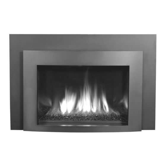
Shown with optional Frosted White Glass Media Kit
www.kozyheat.com
July 2010
MPS-30-REV-02
Advertisement
Table of Contents
Troubleshooting

Related Manuals for kozy heat MPS-30 Minneapolis


Summary of Contents for kozy heat MPS-30 Minneapolis
- Page 1 This appliance is only for use with the type (s) of gas indicated on the rating plate. A conversion kit is supplied with the appliance. WARNING HOT GLASS WILL CAUSE BURNS. DO NOT TOUCH GLASS UNTIL COOLED. NEVER ALLOW CHILDREN TO TOUCH GLASS. July 2010 MPS-30-REV-02 www.kozyheat.com...
- Page 3 INTRODUCTION Read this manual before installing or operating this appliance. Please retain this owner‟s manual for future reference. CONGRATULATIONS! We welcome you as a new owner of a Kozy Heat gas fireplace. Kozy Heat products are designed with superior components and materials and assembled by trained craftsmen who take pride in their work.
-
Page 5: Table Of Contents
TABLE OF CONTENTS INTRODUCTION GLASS MEDIA KIT INSTALLATION Introduction and Homeowner Reference Information Glass Media Kit Installation CONTENTS OPERATING INSTRUCTIONS Table of Contents Wiring Schematics SAFETY INFORMATION Valve and Pilot Assembly Components Safety Information Control Module Components FEATURES Remote Control Components Features Information and Remote Control Operation 23-26... -
Page 6: Safety Information
SAFETY INFORMATION This fireplace has been tested to and complies with ANSI Z21.88-2009·CSA 2.33-2009·CSA P.4.1-09 “VENTED GAS FIREPLACE HEATERS” by OMNI-Test Laboratories, Portland, OR. Installation must conform with local building codes or in the absence of local building codes, with the National Fuel Gas Code, ANSIZ223.1/NFPA 54 - Current Edition, or the Natural or Propane Installation Code, CSAB149.1 Installation and repair should be done only by a qualified service person. -
Page 7: Features
FEATURES Please consult with your dealer for a detailed list of optional accessories available for this fireplace insert. STANDARD FEATURES High efficiency High quality lifetime glass 17-1/2” x 25-5/8” (445 mm x 651 mm) Quick latch glass frame assembly Black firebox liner Black Glass Media Kit IPI control system with remote control Engineer-designed burner system... -
Page 8: Commonwealth Of Massachusetts Information
COMMONWEALTH OF MASSACHUSETTS REQUIREMENTS NOTE: The following requirements reference various Massachusetts and national codes not contained in this manual. For all sidewall horizontally vented gas fueled equipment installed in every dwelling, building or structure used in whole or in part for residential purposes, including those owned or operated by the Commonwealth and where the side wall exhaust vent termination is less than (7) feet above finished grade in the area of the venting, including but not limited to decks and porches, the following requirements shall be satisfied: INSTALLATION OF CARBON MONOXIDE DETECTORS... -
Page 9: Specifications
Figure 6a PARTS DIAGRAM WARNING: Failure to position components in accordance with these diagrams or failure to use only parts specifically approved for use with MPS-30 may result in property damage or personal injury. Fireplace insert Air chute Module panel assembly... -
Page 10: Minimum Clearances To Combustibles
SPECIFICATIONS MINIMUM CLEARANCES TO COMBUSTIBLES 19" 483mm 14" 356mm 22" 9" 559mm 229mm 17" 432mm 12" 305mm 5" 0" 127mm 4" " 102mm 64mm 8" 0" Hearth Protection 203mm 13mm Floor Protector Combustible Floor 3" 76mm Combustible Material Figure 7a PAGE 7... -
Page 11: Components List
SPECIFICATIONS #MPS-30 COMPONENTS PART NUMBER DESCRIPTION MPS-600-IPI Control Board Assembly 700-203 Manual Gas Shut-off Valve MPS-135 Burner Assembly RFD-B-900 Firebox Liner Set 101-BLK Black Glass Media Kit JOR-057T Glass Frame Assembly OCK-A53L-IPI LP Conversion Kit 816-CL1 Co-Linear Air Duct 700-208... -
Page 12: Existing Fireplace Specifications
EXISTING FIREPLACE SPECIFICATIONS THIS INSERT IS APPROVED FOR INSTALLATION IN MASONRY AND FACTORY-BUILT SOLID FUEL BURNING FIREPLACES. EXISTING FIREPLACE REQUIREMENTS The existing fireplace & chimney must be clean and in good working order and constructed of non-combustible materials. A gas line must be able to be installed to the insert. Provisions made to provide electrical power for operation. -
Page 13: Prepare Existing Fireplace
PREPARE EXISTING FIREPLACE EXISTING FIREPLACE MINIMUM OPENING REQUIREMENTS Minimum Requirements (A) Height: ……….19-3/4" (501 mm) (B) Front Width:…30" (762 mm) (C) Depth:………...15-5/16" (389 mm) (D) Back Width:….24-5/16" ( 618mm) Figure 10a PREPARE EXISTING FIREPLACE ATTENTION: Any removed parts must be capable of reinstallation if this insert is ever removed (removal of rivets or screws is acceptable). Any removed parts must be capable of reinstallation if this insert is ever removed (removal of rivets or screws is acceptable). -
Page 14: Gas Line Connection
1-1/2"(38 mm) or less may be drilled through the lower sides or bottom of the firebox in a proper workmanship like manner. This access hole must be plugged with non-combustible insulation after the gas supply line has been installed. MPS-30 NATURAL GAS... -
Page 15: Conversion Kit Instructions
CONVERSION KIT INSTRUCTIONS IMPORTANT: This fireplace is NAT gas ready. If converting to LP gas, do so now before installing into existing fireplace. #OCK-A42N-IPI NAT GAS CONVERSION KIT / #OCK-A53L-IPI LP GAS CONVERSION KIT WARNING: This conversion kit shall be installed by a qualified service agency in accordance with the manufacturers instructions and all applicable codes and requirements of the authority having jurisdiction. - Page 16 CONVERSION KIT INSTRUCTIONS COMPLETE THE CONVERSION: Adjust burner tube venturi to correct setting by loosening screws adjusting cap and retightening screw. CORRECT SETTINGS: NAT: 1/16” (2mm) open / L.P: 100% open Re-install burner into fireplace, making sure orifice is properly seated inside burner venturi and lip on burner front is seated inside firebox.
-
Page 17: Glass Frame Assembly / Clean Face Frame Removal & Installation
GLASS FRAME / SCREEN FRONT WARNING: DO NOT OPERATE THIS FIREPLACE WITH GLASS REMOVED, CRACKED OR BROKEN. REPLACEMENT OF GLASS FRAME ASSEMBLY, #JOR-057T SHOULD BE DONE BY A LICENSED OR QUALIFIED SERVICE PERSON. WARNING: DO NOT REMOVE THESE COMPONENTS WHEN HOT! REMOVE GLASS FRAME ASSEMBLY Upper tab (1 ea. -
Page 18: Air Duct Removal
INSTALLATION AIR DUCT REMOVAL Remove refractory clips from inside top of firebox. Remove side firebox panels Remove (3) screws securing firebox liner back and baffle to firebox back wall. Remove liner. Pull baffle forward and down to remove. Remove access plate (secured with (2) screws) from firebox ceiling. Locate and remove nuts securing air duct top to firebox;... -
Page 19: Run Vent System Through Existing Chimney
RUN VENT SYSTEM THROUGH EXISTING CHIMNEY We strongly suggest wrapping first 3 ft.(914 mm) of vent system below termination cap with non-faced fiberglass insulation (secure with wire) before running it through existing chimney. This will prevent cold air from coming down existing chimney. DO NOT USE THIS METHOD IF YOU ARE STUBBING COMBUSTION AIR PIPE FROM BOTTOM OF EXISTING CHIMNEY. -
Page 20: Connect Vent System To Air Duct
VENT SYSTEM CONNECTION Sheet metal screws (3 total) Sealant Figure 17a Figure 17b Figure 17c 1. Place air duct (previously removed, page 15) into existing fireplace opening. 2. Place a bead of sealant (provided) around exhaust collar (“EX” marking) Slide exhaust pipe over “EX” collar on air duct. Secure with (3) ½"... -
Page 21: Glass Media Kit Installation
GLASS MEDIA INSTALLATION ATTENTION: Do not operate this fireplace without glass media installed. Various colors available. See Dealer for details. WARNING: Do not block pilot assembly with glass media. A blocked pilot assembly may result in a delayed ignition. Install glass media onto burner assembly and pilot shield, being careful not to block pilot assembly. DO NOT BLOCK THIS AREA Shown with optional Frosted White media kit for clarity purposes. -
Page 22: Wiring Schematics
WIRING SCHEMATICS IMPORTANT: THIS SYSTEM REQUIRES ELECTRICITY (110 V) AND / OR BATTERIES TO OPERATE. USING BATTERY BACK UP WILL OPERATE BURNER ONLY. FAN COMPONENTS WILL NOT FUNCTION ON BATTERY BACK-UP POWER. Figure 19a PAGE 19... -
Page 23: Valve And Pilot Assembly Components
VALVE & PILOT ASSEMBLY COMPONENTS PILOT IGNITER FLAME SENSOR IPI PILOT ASSEMBLY BLACK CAP OUTLET (MANIFOLD) PRESSURE SCREW PILOT INTERNAL SOLENOID CONNECTION LOW LIMIT SCREW VALVE STEP MOTOR STEP MOTOR WIRE HARNESS PILOT ADJUSTMENT SCREW INLET PRESSURE SCREW MAIN VALVE INTERNAL SOLENOID CONNECTION IPI GAS VALVE Figure 20a PAGE 20... -
Page 24: Control Module Components
CONTROL MODULE COMPONENTS VALVE STEP MOTOR LEARN BUTTON COMMUNICATION LINK TERMINAL TO EXTENSION MODULE AC ADAPTOR CONNECTION MAIN CONTROL MODULE „I‟ IGNITER PILOT CONTINUOUS PILOT REMOTE ON/OFF „S‟ SENSOR PILOT CONNECTION ON/OFF SWITCH SWITCH CONNECTION NON-OPERATIONAL BACK-UP BATTERY PACK POWER TO LIGHT KIT (not available in all models ) COMMUNICATION LINK NON-OPERATIONAL... -
Page 25: Remote Control Components
REMOTE CONTROL INFORMATION MANUAL ON / OFF THERMOSTAT MODE ICON ROOM TEMPERATURE BATTERY LIFE ICON SET TEMPERATURE (visible only in THERMO MODE) FAN SPEED LIGHT LEVEL CHILD PROOF ICON CONTINUOUS PILOT FLAME HEIGHT Figure 22a PAGE 22... -
Page 26: Information And Remote Control Operation
IPI INFORMATION ELECTRICAL WARNING AND INFORMATION: Electrical wiring must be installed by a licensed electrician. Do NOT wire 110V to wall switch. Uninterrupted or continuous power is required at all times in IPI systems EXCEPT when using battery back-up. Incorrect wiring will override IPI safety lockout and may cause an explosion. Disconnect 110V before servicing. - Page 27 IPI INFORMATION MATCHING SECURITY CODES Before matching security codes make sure 120V AC is connected and powered to fireplace, and hand held remote control is installed with (2) AA batteries. It may be necessary to program main control module (located on right side of firebox) to LEARN the hand held remote control security code upon initial use, if batteries are replaced, or if a replacement remote control is purchased from your dealer.
- Page 28 REMOTE CONTROL INFORMATION cont. CONTINUOUS PILOT FEATURE: Activation of this optional feature is accomplished by pressing the PILOT button once. The continuous pilot icon will appear on the LCD screen. Pressing PILOT button again will de-activate this feature. This feature can also be activated via CONTINUOUS PILOT switch on Main Control Module.
- Page 29 REMOTE CONTROL INFORMATION cont. FLAME MODE: This remote will operate the flame, allowing for (6) different flame height levels. When MAIN FLAME button is pressed, FLAME level setting will flash on the LCD screen. Press UP or DOWN buttons to select desired flame level.
-
Page 30: Lighting And Shutdown
LIGHTING AND SHUTDOWN FOR YOUR SAFETY - READ BEFORE LIGHTING WARNING: IF YOU DO NOT FOLLOW THESE INSTRUCTIONS EXACTLY, A FIRE OR EXPLOSION MAY RESULT, CAUSING PROPERTY DAMAGE, PERSONAL INJURY OR LOSS OF LIFE. DUE TO HIGH SURFACE TEMPERATURES, KEEP CHILDREN, CLOTHING AND FURNITURE AWAY. This appliance needs fresh air for safe operation and must be installed so there are provisions for adequate combustion and ventilation air. - Page 31 LIGHTING AND SHUTDOWN (cont.) LIGHTING STOP! Read safety information on previous page and front cover of this manual before continuing. Turn off all electrical power to fireplace. Power OFF ATTENTION: This fireplace is equipped with an ignition device which automatically lights the pilot. DO NOT light the pilot by hand.
-
Page 32: Pressure Testing
PRESSURE TESTING IMPORTANT NOTICE: Pressure check taps for manifold (outgoing) and inlet (incoming) pressure have been incorporated into the valve. The pressure tap marked OUT measures outgoing pressure and the pressure tap marked IN measures incoming pressure. Follow instructions below for proper testing procedures. NOTE: The appliance and its individual shutoff valve must be disconnected from the gas supply piping system during any pressure testing of that system at pressures in excess of ½... -
Page 33: Error Codes
ERROR CODES IGNITION SAFETY: Protection for Ignition System Error Code: One beep every one second. Description of Fault: Warns users if pilot is not successfully ignited in 60 seconds. How to Clear: Press MODE button to OFF then to ON to re-attempt ignition. What to Check: Ensure gas supply is turned on. -
Page 34: Finalizing The Installation
FINALIZING THE INSTALLATION FLAME APPEARANCE: Flame appearance is affected by several factors including altitude, venting configuration and fuel quality. Although the venturi settings have been factory set, adjustments may be necessary for optimal performance and visual aesthetics. When fireplace is first lit, the flames will be blue. Flames will gradually turn yellowish-orange during first 15 minutes of operation. If flames remain blue or become dark orange with evidence of sooting (black tips), the burner tube venturis may need adjustment. -
Page 35: Maintenance
MAINTENANCE The appliance is required to be inspected at least once a year by a professional service person. The compartments on sides of firebox must be cleaned at least once a year, more frequent cleaning may be required due to excessive lint from carpeting, bedding materials, or other fibrous materials. -
Page 36: Troubleshooting
TROUBLESHOOTING MAIN CONTROL MODULE WILL NOT LEARN TRANSMITTER Ensure REMOTE/OFF switch on side of main control module is set to REMOTE. Make sure batteries in both the hand held remote and backup battery pack are installed in the proper direction and are not drained. Verify hand held remote indicates a signal is being sent. -
Page 37: Troubleshooting
TROUBLESHOOTING MAIN FLAME WILL NOT LIGHT Verify gas supply is turned on. Ensure pilot flame will ignite. If not, see pilot flame troubleshooting on previous page. Make sure white cap leads marked MAIN from module are securely connected to terminals marked MAIN on valve body. Make certain pilot flame is in contact with flame rectification sensor on pilot assembly. -
Page 38: Replacement Parts List
MPS-30 REPLACEMENT PARTS LIST Replacement parts are available through your local dealer. Contact them for availability and pricing. MPS-30 BOARD SYSTEM AND PARTS MPS-600-IPI Minneapolis-IPI Control Board - Nat Gas 700-168 #35 IPI LP Gas Pilot Orifice MPS-601-IPI Minneapolis-IPI Control Board - LP Gas... - Page 40 LIMITED WARRANTY PAGE 36...
Need help?
Do you have a question about the MPS-30 Minneapolis and is the answer not in the manual?
Questions and answers