
Related Manuals for Advantech ITA-2000


Summary of Contents for Advantech ITA-2000
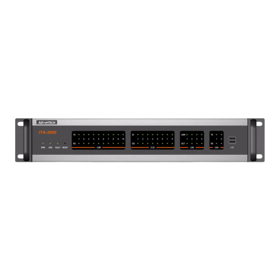
- Page 1 User Manual ITA-2000 2U Rackmount System Intel Atom N270 4 LAN, 10 COM, 2 CAN, 16 DIO & PC/104+ 带 Intel Atom N270、4 x LAN、10 x COM、2 x CAN、16 x DIO & PC/ 104+ 的 2U 上架式系统...
- Page 2 No part of this manual may be reproduced, copied, translated or transmitted in any form or by any means without the prior written permission of Advantech Co., Ltd. Information provided in this manual is intended to be accurate and reliable. How- ever, Advantech Co., Ltd.
-
Page 3: Safety Instructions
CAUTION: Always completely disconnect the power cord from your chassis whenever you work with the hardware. Do not make connections while the power is on. Sensitive electronic components can be damaged by sudden power surges. ITA-2000 User Manual/ 用户手册... - Page 4 设备外壳的开口是用于空气对流,从而防止设备过热。请不要覆盖这些开口。 当您连接设备到电源插座上前,请确认电源插座的电压是否符合要求。 请将电源线布置在人们不易绊到的位置,并不要在电源线上覆盖任何杂物。 请注意设备上的所有警告标示。 如果长时间不使用设备,请将其同电源插座断开,避免设备被超标的电压波动损 坏。 请不要让任何液体流入通风口,以免引起火灾或者短路。 请不要自行打开设备。为了确保您的安全,请由经过认证的工程师来打开设备。 如遇下列情况,请由专业人员来维修: 电源线或者插头损坏; 设备内部有液体流入; 设备曾暴露在过于潮湿的环境中使用; 设备无法正常工作,或您无法通过用户手册来使其正常工作; 设备跌落或者损坏; 设备有明显的外观破损。 注意:计算机配置了由电池供电的实时时钟电路,如果电池放置不正确,将有爆 炸的危险。因此,只可以使用制造商推荐的同一种或者同等型号的电池进行替 换。请按照制造商的指示处理旧电池。 计算机的光盘驱动符合相应的安全标准,如 IEC 60825 等。 本品符合 FCC 规则第 15 款限制。操作符合下列两种情况: (1)此装置不可产生干扰,且 (2)此装置必须接受任何干扰,包括可能导致非预期操作的干扰。 注意:无论何时进行操作,请务必完全断开机箱电源。不可在电源接通时进行设 备连接,以避免瞬间电涌损坏敏感电子元件。 注意:接触母板、无源底板或附加卡时,请务必使自己接地来移除身体所附的静 电。由于现在的电子设备对静电十分敏感,为了安全起见,请使用接地腕环。请 将所有电子元件放在无静电的表面或静电屏蔽袋中。 注意:任何未经验证的组件都可能对设备造成意外损坏。为保证安装正确,请只 使用附件盒内提供的组件,如螺丝。 ITA-2000 User Manual/ 用户手册...
- Page 5 Our dealers are well trained and ready to give you the support you need to get the most from your Advantech products. In fact, most problems reported are minor and can be easily solved over the phone.
- Page 6 Because of Advantech’s high quality-control standards and rigorous testing, most of our customers never need to use our repair service. If an Advantech product is defec- tive, it will be repaired or replaced at no charge during the warranty period. For out- of-warranty repairs, you will be billed according to the cost of replacement materials, service time and freight.
- Page 7 It should be free of marks and scratches and in perfect working order upon receipt. As you unpack the ITA-2000, check it for signs of ship- ping damage. (For examples: box damage, scratches, dents, etc.) If it is damaged or it fails to meet the specifications, notify our service department or your local sales representative immediately.
- Page 8 ITA-2000 User Manual/ 用户手册 viii...
-
Page 9: Table Of Contents
Figure 2.3 COM3 ~ COM10 setting/COM3 ~ COM10 设置..10 Table 2.4: JCOMT3~10 ............. 10 Figure 2.4 JCOMT3 ~ 10 setting/JCOMT3 ~ COM10 设置 ..10 Connectors of Rear I/O/ 后部 I/O 接口......11 Figure 2.5 ITA-2000 I/O Connectors drawing/ITA-2000 I/O 接口 图..........11 COM Connector/COM 端口 .........11 2.4.1 Figure 2.6 D-sub COM Connector/D-sub COM 端口... - Page 10 Installing the Disk Drive/ 安装磁盘驱动 ..... 51 5.1.3 Figure 5.4 Loosen the four screws on the shockproof bracket/ 卸 载防冲击支架上的 4 个螺丝 ..... 52 Figure 5.5 Installing a Hard Disk into the shockproof bracket/ 将 HDD 安装在防冲击支架上 ....... 52 ITA-2000 User Manual/ 用户手册...
- Page 11 Figure B.1 CAN WDM&CE configure setting/CAN WDM&CE 配置 .69 Send/ 发送..........70 B.1.3 Figure B.2 CAN Send test of WDM&CE/CAN WDM&CE 发送测试 .70 Receive/ 接收 ...........71 B.1.4 Figure B.3 CAN Receive test of WDM&CE/CAN WDM&CE 接收测试 ..........71 ITA-2000 User Manual/ 用户手册...
- Page 12 ITA-2000 User Manual/ 用户手册...
-
Page 13: Chapter 1 General Information 概述
Chapter General Information 概述 This chapter provides general informnation about the ITA-2000. 本章介绍了 ITA-2000 的基本信息。... -
Page 14: Introduction/ 产品简介
Introduction/ 产品简介 The ITA-2000 is a 2U-high rackmount industrial computer chassis. It meets a variety of application needs for train monitoring. This powerful computing platform can oper- ate under harsh conditions 24 hours a day, 7 days a week. ITA-2000 是一款 2U 上架式工业机箱。... -
Page 15: Power Supply Options/ 电源选项
Power Supply Options/ 电源选项 ITA-2000 comes with 120 W power supply. It can support AC 100 ~ 240 V / DC 110 ~ 220 V depending on the model required. ITA-2000 带有 120 W 电源, 根据所需型号可提供 AC 100 ~ 240 V / DC 110 ~ 220 V。... -
Page 16: Dimension Diagram/ 产品尺寸
Dimension Diagram/ 产品尺寸 Figure 1.1 Dimension diagram/ 尺寸图 ITA-2000 User Manual/ 用户手册... -
Page 17: Chapter 2 H/W Installation 硬件安装
Chapter H/W Installation 硬件安装 This chapter provides H/W Instal- lation about the ITA-2000. 本章介绍了 ITA-2000 的硬件安装信 息。... -
Page 18: Introduction/ 简介
Data being received/transmitted on SATA 黄色 亮起 数据正在通过 SATA 进行接收 / 传输 No data being received/transmitted on SATA 熄灭 没有数据正在通过 SATA 进行接收 / 传输 System temperature too high 亮起 黄色 系统温度过高 FAULT System is safe 熄灭 系统安全 ITA-2000 User Manual/ 用户手册... - Page 19 CAN 总线数据正在进行传输 No data being transmitted N = 1~ 2 熄灭 没有数据正在进行传输 Yellow CAN bus data being received CAN Rx (Port N) 亮起 黄色 CAN 总线数据正在进行接收 No data being received N = 1~ 2 熄灭 没有数据正在进行接收 ITA-2000 User Manual/ 用户手册...
-
Page 20: Jumpers/ 跳线
Jumper Description/ 跳线说明 2.3.1 You may configure the ITA-2000 to match the needs of your application by setting jumpers. A jumper is a metal bridge used to close an electric circuit. It consists of two metal pins and a small metal clip (often protected by a plastic cover) that slides over the pins to connect them. -
Page 21: Jumper And Connector Location/ 跳线和接口位置
功能 Close (5-6, 7-9, 8-10, 13-15, 14-16) RS-232 (Default) 闭合 (5-6、7-9、8-10、13-15、14-16) RS-232 (默认) Close (3-4, 9-11, 10-12, 15-17, 16-18) RS-422 闭合 (3-4、9-11、10-12、15-17、16-18) Close (1-2, 9-11, 10-12, 15-17, 16-18) RS-485 闭合 (1-2、9-11、10-12、15-17、16-18) Figure 2.2 COM2 setting/COM2 设置 ITA-2000 User Manual/ 用户手册... -
Page 22: Table 2.3: Jsetcom3~10
Data + set up Terminator 闭合 (2-4) Data+ 设置终端电阻 Open (1-3) Data - Non Terminator 断开 (1-3) Data- 无终端电阻 Open (2-4) Data + Non Terminator 断开 (2-4) Data+ 无终端电阻 Figure 2.4 JCOMT3 ~ 10 setting/JCOMT3 ~ COM10 设置 ITA-2000 User Manual/ 用户手册... -
Page 23: Connectors Of Rear I/O/ 后部 I/O 接口
ITA-2000 provides four D-sub 9-pin and three phoenix 10-pin connectors, among which eight COM ports support RS-232/422/485 with isolation. ITA-2000 提供了 4 个 D-sub 9 针和 3 个 phoenix 10 针接口, 其中 8 个 COM 端口支持带 隔离 RS-232/422/485。 COM 1/2/9/10 of D-Sub Connector/D-Sub COM 1/2/9/10 端口... -
Page 24: Vga Connector/Vga 接口
Data+ Data- VGA Connector/VGA 接口 2.4.2 ITA-2000 offers a standard VGA Interface connector by D-sub 15-pin female connec- tor. ITA-2000 提供 1 个标准的 D-sub 15 针母型 VGA 接口。 Figure 2.8 VGA D-sub Connector/VGA D-sub 接口 Table 2.7: VGA Connector Pin Assignments/VGA 接口针脚定义... -
Page 25: Usb Connector/Usb 接口
Ethernet Connector (LAN1 ~ LAN4)/ 以太网接口 (LAN1 ~ 2.4.4 LAN4) ITA-2000 is equipped with four Intel 82574 Ethernet controllers that are fully compli- ant with IEEE 802.3u 10/100/1000Mbps standard. ITA-2000 带有 4 个 Intel 82574 以太网控制器,完全符合 IEEE 802.3u 10/100/1000 Mbps 标准。... -
Page 26: Dio Connector/Dio 接口
MDI3- DIO Connector/DIO 接口 2.4.5 ITA-2000 provides one phoenix 18-pin male connectors, which offers Digital Input/ Output communication interface. If client want to use DIO, please find the Pin assign- ment as following. ITA-2000 提供 1 个 phoenix 18 针母型数字输入 / 输出通信接口。用户使用 DIO 时,请... -
Page 27: Figure 2.12D-Sub Com Connector/D-Sub Com 接口
Power ON/OFF Button / Power Input Connector/电源开关按钮/ 电源输入接口 ITA-2000 comes with a Power ON/OFF button and AC inlet, its support AT function with that carries 110 V ~ 240 VAC power input. ITA-2000 带有电源开关按钮和 AC 插座,支持 AT 功能,具有 110 V ~ 240 VAC 电源输... - Page 28 ITA-2000 User Manual/ 用户手册...
-
Page 29: Bios Operation Bios 操作
Chapter BIOS Operation BIOS 操作 This chapter describes how to set BIOS configuration data. 本章介绍了如何进行 BIOS 数据设置。... -
Page 30: Introduction/ 简介
CPUs from 386 through Pentium, AMD Geode, K7 and K8 (including multiple proces- sor platforms), and VIA Eden C3 and C7 CPUs. You can use Advantech’s utilities to select and install features that suit your needs and your customers’ needs. -
Page 31: Main Menu/ 主菜单
This setup page includes PnP OS and PCI device configuration. PC Health Status This setup page includes the system auto detect CPU and system temperature, voltage, fan speed. Frequency/Voltage Control This setup page includes CPU host clock control, frequency ratio and voltage. ITA-2000 User Manual/ 用户手册... - Page 32 PnP/PCI 配置 该设置包含 PnP OS 和 PCI 设备配置的所有选项。 PC 健康状态 该设置包含系统自动检测 CPU 以及系统温度、电压和风扇速度。 频率 / 电压控制 该设置包含 CPU 主时钟控制、频率和电压。 加载最优化默认设置 该设置包含加载系统最优化数值以获得最优化配置。 设置密码 设置、更改或禁用密码。 保存并退出设置 将 CMOS 数值设置保存在 CMOS 然后退出 BIOS 设置。 不保存便退出设置 取消所有 CMOS 数值更改并退出 BIOS 设置。 ITA-2000 User Manual/ 用户手册...
-
Page 33: Standard Cmos Features/ 标准 Cmos 特性
All, But Keyboard The system boot will not stop for a keyboard error; it will stop for all other errors. (Default value) Base Memory The POST of the BIOS will determine the amount of base (or conventional) memory installed in the system. ITA-2000 User Manual/ 用户手册... - Page 34 选择 EGA 或 VGA 视频。 停止引导 [All Errors] 此项用于决定在系统引导过程中遇到错误时,系统是否停止引导。 No Errors 遇到任何错误系统都不会停止运行。 All Errors BIOS 检测到非致命错误时,系统将停止运行。 All,But Keyboard 遇到键盘错误时系统将停止运行;其它错误时不会停止运行 (默认设置) 。 基本内存 BIOS POST 将决定系统的基本 (常规)内存。 扩展内存 BIOS POST 将决定系统的扩展内存 (CPU 内存地址映射中大于 1 MB) 。 总内存 此项显示了总的系统内存大小。 ITA-2000 User Manual/ 用户手册...
-
Page 35: Advanced Bios Features/ 高级 Bios 特性
Gate A20 Option [Fast] This item enables users to switch A20 control by port 92 or not. Typematic Rate Setting [Disabled] This item enables users to set the two typematic controls items. – Typematic Rate (Chars/Sec) ITA-2000 User Manual/ 用户手册... - Page 36 “USB-FDD” 、 “USB-ZIP” 、 “USB-CDROM” 、 “LAN”和 “Disabled” 。 启动时数字锁定键状态 [On] 默认为 “On” 。 On (默认) 软件盘为数字键。 软键盘为方向键。 Gate A20 选择 [Fast] 此项允许用户通过端口 92 切换进行 A20 控制。 键入速率设定 [Disabled] 此项允许用户设置两种键入控制选项。 键入速率 (字 / 秒) – 键入速率是指由键盘控制器决定的键击重复速率。8 种设置分别为: 6、8、10、 12、15、20、24 和 30。 字元输入延迟 (msec) – ITA-2000 User Manual/ 用户手册...
-
Page 37: Advanced Chipset Features/ 高级芯片组特性
Options: Dis- abled (default), Enabled PCI Express Root port Function This item allows the user to adjust PCIE port on, off or auto. On-Chip Frame Buffer Size[8 MB] ITA-2000 User Manual/ 用户手册... - Page 38 板载帧缓冲大小可设置为 1 MB 或 8 MB。 DVMT 模式 [DVMT] 此项用于选择视频内存模式。选项为 “Fixed” 、 “DVMT”和 “BOTH” 。 DVMT/FIXED 内存大小 此项允许用户调节分配给显存的 DVMT/ 系统内存大小。 启动显示 [Auto] 此项允许用户确定启动显示模式。 LVDS 面板类型 SDVO 模块 此项允许用户确定显示屏分辨率。 显卡优先设置 [PCI Slot] 此项为视频输出启动设置:PCI Express 或 Onboard device (板载设备) 。 ITA-2000 User Manual/ 用户手册...
-
Page 39: Integrated Peripherals/ 集成外围设备
组;以上界面仅作参考,若芯片组特性不同界面也会不同。 OnChip IDE Device This item enables users to set the OnChip IDE device status, including some of new chipsets also support SATA devices (Serial-ATA). 板载 IDE 设备 此项目允许用户设置 OnChip IDE 设备状态,包括一些也支持 SATA 设备 (串行 ATA)的芯片组。 ITA-2000 User Manual/ 用户手册... - Page 40 Onboard Serial port 1 [3F8 / IRQ4] This item allows user to adjust serial port 1 of address and IRQ. – Onboard Serial port 2 [ 2F8/ IRQ3] This item allows user to adjust serial port 2 of address and IRQ. ITA-2000 User Manual/ 用户手册...
- Page 41 USB1.0 控制器 – 若系统中含有通用串行总线 (USB)控制器且用户有 USB 外围设备,请选择 Enabled。选项为 “Enabled”和 “Disabled” 。 USB2.0 控制器 – 此项用于启用或禁用 USB2.0 控制器。BIOS 自身可能不支持高速 USB。若 BIOS 支持高速 USB,当安装有高速设备时该功能将自动启动。选项为 “Enabled” 和 “Disabled” 。 USB 工作模式 – 将 USB2.0 控制器设置为高速 (480 Mbps)或完全速度 (12 Mbps) 。 ITA-2000 User Manual/ 用户手册...
-
Page 42: Power Management Setup/ 电源管理设定
The system shuts down with the exception of a refresh current to the system memory. Run VGA BIOS if S3 Resume [Auto] This item allows system to reinitialize VGA BIOS after system resume from ACPI S3 mode. Power Management [User Define] ITA-2000 User Manual/ 用户手册... - Page 43 The choices are “Enabled” and “Disabled”. If enabled, the fields that follow indi- cate dates and times of alarm settings. 电源类型 [ATX] 此项允许用户将电源类型设置为 ATX 或 AT 模式。 ACPI 功能 [Enabled] 此项定义了 ACPI(高级配置和电源管理)功能,可将硬件状态信息传达给操作系 统显示,并与 PC 和系统设备进行通信,从而提高了电源管理性能。 ACPI 挂起类型 [S3(STR)] 此项允许用户在挂起模式时选择休眠状态。 S1 (POS) 该挂起模式相当于软件关闭。 S3 (STR) 系统关闭,但系统内存进行刷新时除外。 ITA-2000 User Manual/ 用户手册...
- Page 44 网络唤醒 [Disabled] 此项允许用户通过 LAN 进行开机。选项为 “Enabled”和 “Disabled” 。 响铃开机 [Disabled] 启用此项可使用调制解调器开机功能。选项为 “Enabled”和 “Disabled” 。 通过 USB 键盘将系统从 S3 状态唤醒 [Disabled] 选择此项,用户可通过 USB 键盘将系统从 S3 挂起状态唤醒。选项为 “Enabled” 和 “Disabled” 。 定时开机 [Disabled] 选项为 “Enabled”和 “Disabled” 。启用后,用户可以在此设置开机的日期和 时间。 ITA-2000 User Manual/ 用户手册...
-
Page 45: Pnp/Pci Configurations/Pnp/Pci 配置
资源控制 [Auto(ESCD)] 此处的选项为 “Auto (ESCD)”或 “Manual”。选择 “Manual”要求用户从下列 每个子菜单选择资源。选择 “Auto (ESCD)”将会自动配置所有启动设备和即插 即用设备,但是用户必须使用 Windows 95 或更高版本的系统。 PCI/VGA 调色板配置 [Disabled] 此项用于解决一些非标准 VGA 卡所造成的问题。内置 VGA 系统不需要此功能。 INT 针脚 1-8 定义 此项允许用户选择用户系统 PCI 接口所连接设备分配的中断请求 (IRQ) 。 最大有效载荷大小 [4096] 此项允许用户调整最大 TLP (事务层包)有效载荷大小。 ITA-2000 User Manual/ 用户手册... -
Page 46: Pc Health Status/Pc 健康状态
机箱打开报警 [Disabled] 启用此项可检测机箱打开或关闭。 关机温度 [Disabled] 当系统超过预设值时系统将自动关机。 Frequency/Voltage Control/ 频率 / 电压控制 3.2.9 Auto Detect PCI Clk [Enable] This item enables users to set the PCI Clk either by automatic system detection or manually. Spread Spectrum [Disabled] ITA-2000 User Manual/ 用户手册... -
Page 47: Load Optimized Defaults/ 加载最优化默认设置
Note! Load Optimized Defaults loads the default system values directly from ROM. Useful if the stored record created by the Setup program should ever become corrupted (and therefore unusable). 注! 加载最优化默认设置将从 ROM 中直接加载默认系统值。当设置程序创建 的存储记录遭到损坏时该功能会很有用 (否则无用) 。 ITA-2000 User Manual/ 用户手册... -
Page 48: Set Password/ 密码设定
Select Set Password again, and at the “Enter Password” prompt, enter the new password and press <Enter>. At the “Confirm Password” prompt, retype the new password, and press <Enter>. Select Save to CMOS and EXIT, type <Y>, then <Enter>. ITA-2000 User Manual/ 用户手册... - Page 49 从 CMOS 配置工具主菜单中选择 “Set Password”选项,然后按 <Enter> 键。 看到 “Enter Password”后,输入当前密码然后按 <Enter> 键。 看到 “Confirm Password”后,再次输入密码然后按 <Enter> 键。 再次选择 “Set Password” ,弹出 “Enter Password”后,不要输入任何字符然 后按 <Enter> 键。 弹出 “Confirm Password”后,不要输入任何字符然后按 <Enter> 键。 选择 “Save to CMOS and EXIT” ,输入 <Y>,然后按 <Enter> 键。 ITA-2000 User Manual/ 用户手册...
-
Page 50: Save & Exit Setup/ 保存并退出设置
Quit without Saving/ 不保存便退出设置 3.2.13 Note! Typing “Y” will quit the BIOS Setup Utility without saving to CMOS. Typing “N” will return to BIOS Setup Utility. 注! 输入 “Y”将退出 BIOS 配置工具而不会将用户设置数值保存在 CMOS 中。 输入 “N”将返回 BIOS 配置工具。 ITA-2000 User Manual/ 用户手册... -
Page 51: Chipset Software Installation Utility
Chapter Chipset Software Installation Utility 芯片组软件安装实用程 序 This chapter describes how to Installation software and utility. 本章介绍了如何安装软件和实用程 序。... -
Page 52: Introduction/ 简介
通用的 Windows 编程工具中,如 Visual C++、Visual Basic、Borland C++ Builder 和 Borland Delphi。 Driver Installation/ 驱动安装 Insert the driver CD into your system’s CD-ROM drive. You can see the ITA-2000 driver folder items. 将驱动光盘插入系统 CD-ROM 驱动,用户即可看到 ITA-2000 驱动文件夹。 ITA-2000 User Manual/ 用户手册... -
Page 53: Chipset Windows Driver Setup/ 芯片组 Windows 驱动安装
Navigate to the "Drv_INF" folder and click "infinst.exe" to complete the installa- tion of the driver. 将 驱 动光 盘 插入 系 统 CD-ROM 驱 动,用户 即 可看 到 ITA-2000 驱动 文 件夹。找 到 “Drv_INF”文件夹然后双击 “infinst.exe”完成驱动安装。 ITA-2000 User Manual/ 用户手册... -
Page 54: Vga Windows Driver Setup/Vga Windows 驱动安装
Navigate to the "Drv_VGA" folder and click "vga.exe" to complete the installa- tion of the drivers. 将驱 动 光 盘插 入 系统 CD-ROM 驱动,用 户即 可 看到 ITA-2000 驱 动文 件 夹。找 到 “Drv_VGA”文件夹然后双击 “vga.exe”完成驱动安装。 ITA-2000 User Manual/ 用户手册... -
Page 55: Lan Windows Driver Setup/Lan Windows 驱动安装
LAN Windows Driver Setup/LAN Windows 驱动安装 4.2.3 Insert the driver CD into your system’s CD-ROM drive. Select the “Drv_LAN” folder then navigate to the directory for your OS. 将驱动光盘插入系统 CD-ROM 驱动,选择 “Drv_LAN”然后找到操作系统目录。 ITA-2000 User Manual/ 用户手册... -
Page 56: Com Windows Driver Setup/Com Windows 驱动安装
COM Windows Driver Setup/COM Windows 驱动安装 4.2.4 Insert the driver CD into your system’s CD-ROM drive. Navigate to the "Drv_COM” folder and click "PCI_COM" to complete the installation of the drivers. 将驱动光盘插入系统 CD-ROM 驱动,找到 “Drv_COM”文件夹然后双击 “PCI_COM”完 成驱动安装。 ITA-2000 User Manual/ 用户手册... - Page 57 Click “Next“ as the following. 点击 “Next” ,如下图所示。 Click “Next“ as the following. 点击 “Next” ,如下图所示。 ITA-2000 User Manual/ 用户手册...
-
Page 58: Can Windows Driver Setup/Can Windows 驱动安装
CAN Windows Driver Setup/CAN Windows 驱动安装 4.2.5 Insert the driver CD into your system’s CD-ROM drive. Navigate to the "Drv_CAN” folder and click "PCI1680" to complete the installation of the drivers. 将驱动光盘插入系统 CD-ROM 驱动,找到 “Drv_CAN”文件夹然后双击 “PCI1680”完 成驱动安装。 ITA-2000 User Manual/ 用户手册... - Page 59 First make sure hardware can be installed normally, then turn on the computer and enter operating system. You will see the following screen. 请首先确认硬件已正确安装好,然后打开计算机进入操作系统,即可看到以下界面。 ITA-2000 User Manual/ 用户手册...
- Page 60 ITA-2000 User Manual/ 用户手册...
-
Page 61: System Setup 系统安装
Chapter System Setup 系统安装 This chapter introduces the instal- lation process. 本章介绍了安装过程。... -
Page 62: Introduction/ 简介
Introduction/ 简介 The following procedures will instruct you how to install a Memory DIMM, PCI-104 module and disk drive into the ITA-2000 system. 以下步骤将指导用户如何在ITA-2000系统中安装内存DIMM、 PCI-104模块和磁盘驱动。 Removing the Chassis Cover/ 移除机箱顶盖 5.1.1 To remove the chassis cover, please proceed as below. -
Page 63: Installing A Memory Dimm/ 安装内存 Dimm
Installing the Disk Drive/ 安装磁盘驱动 5.1.3 The ITA-2000 comes with a shockproof bracket for an internal 2.5” or 3.5” HDD. Please refer to the following instructions to install the hard disk drive. To install the internal HDD, remove the top cover by releasing the two crews. -
Page 64: Figure 5.5 Installing A Hard Disk Into The Shockproof Bracket/ 将 Hdd 安装在防冲击支架上
Figure 5.4 Loosen the four screws on the shockproof bracket/卸载防冲击支架上 的 4 个螺丝 Figure 5.5 Installing a Hard Disk into the shockproof bracket/将HDD安装在防冲击 支架上 ITA-2000 User Manual/ 用户手册... -
Page 65: 将 Hdd 和防冲击支架放回系统中
Figure 5.6 Return the shockproof bracket with HDD into system/ 将 HDD 和防冲击 支架放回系统中 Installing a PCI-104 Module/ 安装 PC-104 模块 5.1.4 The ITA-2000 supports PCI-104 modules depending on the Motherboard specifica- tion. To install the module, just simply insert the module to the corresponding slot as follows: ITA-2000 是否支持 PC-104 模块,取决于母板规格。安装模块时,仅需将模块插入合适... -
Page 66: Installing The Compact Flash/ 安装 Cf
Installing the Compact Flash/ 安装 CF 5.1.5 The ITA-2000 supports one internal CF slot for Compact Flash card type I/II. To install the card, please proceed as follows: Turn the chassis to bottom side and look for the square cover with 4 screws Loosen the four screws;... -
Page 67: Programming The Watchdog Timer
Appendix Programming the Watchdog Timer 看门狗定时器编程... -
Page 68: Programming The Watchdog Timer/ 看门狗定时器编程
Programming the Watchdog Timer/看门狗定时器 编程 The ITA-2000's watchdog timer can be used to monitor system software operation and take corrective action if the software fails to function within the programmed period. This section describes the operation of the watchdog timer and how to pro- gram it. - Page 69 Unlock W83627DHG 解锁 W83627DHG Select register of watchdog timer 选择看门狗定时器 寄存器 Enable the function of the watchdog timer 启用看门狗定时器功能 Use the function of the watchdog timer 使用看门狗定时器功能 Lock W83627DHG 锁定 W83627DHG ITA-2000 User Manual/ 用户手册...
-
Page 70: Table A.1: Watchdog Timer Registers/ 看门狗定时器寄存器
Bit 5:写入 1 立即产生超时信号,并自动返回到 0 (默认 为 0) 。 Bit 4:读取看门狗定时器状态,1 表示定时器 “超时” 。 Write this address to I/O port 2E (hex) to lock the watchdog AA (hex) ----- timer 2. 向 I/O 端口 2E (hex)写入该地址,锁定看门狗定时器 2。 ITA-2000 User Manual/ 用户手册... -
Page 71: Example Program/ 编程示例
Mov al,10 Out dx,al ;----------------------------------------------------------- Dec dx ; Lock W83627DHG Mov al,0aah Out dx,al Enable watchdog timer and set 5 minutes as timeout interval ;----------------------------------------------------------- Mov dx,2eh ; Unlock W83627DHG Mov al,87h Out dx,al Out dx,al ITA-2000 User Manual/ 用户手册... - Page 72 Enable watchdog timer to be reset by mouse ;----------------------------------------------------------- Mov dx,2eh ; Unlock W83627DHG Mov al,87h Out dx,al Out dx,al ;----------------------------------------------------------- Mov al,07h ; Select registers of watchdog timer Out dx,al Inc dx Mov al,08h Out dx,al ;----------------------------------------------------------- ITA-2000 User Manual/ 用户手册...
- Page 73 Dec dx ; Enable the function of watchdog timer Mov al,30h Out dx,al Inc dx Mov al,01h Out dx,al ;----------------------------------------------------------- Dec dx ; Enable watchdog timer to be strobed reset by keyboard Mov al,0f7h Out dx,al Inc dx In al,dx Or al,40h Out dx,al ITA-2000 User Manual/ 用户手册...
- Page 74 Dec dx ; Generate a time-out signal Mov al,0f7h Out dx,al ;Write 1 to bit 5 of F7 register Inc dx In al,dx Or al,20h Out dx,al ;----------------------------------------------------------- Dec dx ; Lock W83627DHG Mov al,0aah Out dx,al ITA-2000 User Manual/ 用户手册...
- Page 75 Mov al,0f6h Out dx,al Inc dx Mov al,10 Out dx,al ;----------------------------------------------------------- Dec dx ; 锁定 W83627DHG Mov al,0aah Out dx,al 启用看门狗定时器功能并将超时间隔设置为 5 分钟。 ;----------------------------------------------------------- Mov dx,2eh ; 锁定 W83627DHG Mov al,87h Out dx,al Out dx,al ;----------------------------------------------------------- ITA-2000 User Manual/ 用户手册...
- Page 76 Dec dx ; 锁定 W83627DHG Mov al,0aah Out dx,al 启用鼠标复位看门狗定时器功能。 ;----------------------------------------------------------- Mov dx,2eh ; 锁定 W83627DHG Mov al,87h Out dx,al Out dx,al ;----------------------------------------------------------- Mov al,07h ; 选择看门狗定时器寄存器 Out dx,al Inc dx Mov al,08h Out dx,al ;----------------------------------------------------------- Dec dx ; 启用看门狗定时器功能 ITA-2000 User Manual/ 用户手册...
- Page 77 Mov al,08h Out dx,al ;----------------------------------------------------------- Dec dx ; 启用看门狗定时器功能 Mov al,30h Out dx,al Inc dx Mov al,01h Out dx,al ;----------------------------------------------------------- Dec dx ; 启用键盘复位看门狗定时器功能 Mov al,0f7h Out dx,al Inc dx In al,dx Or al,40h Out dx,al ;----------------------------------------------------------- ITA-2000 User Manual/ 用户手册...
- Page 78 Out dx,al ;----------------------------------------------------------- Dec dx ; 产生超时信号 Mov al,0f7h Out dx,al ; 向 F7 寄存器 bit 5 写入 1 Inc dx In al,dx Or al,20h Out dx,al ;----------------------------------------------------------- Dec dx ; 锁定 W83627DHG Mov al,0aah Out dx,al ITA-2000 User Manual/ 用户手册...
-
Page 79: Examples Of The Can Transfer Tool Can 转换工具示例
Appendix Examples of the CAN Transfer tool CAN 转换工具示例... -
Page 80: Examples Of The Can Transfer Tool And Programming/Can转换工具和编程 示例
Examples of the CAN Transfer Tool and Programming/CAN 转换工具和编程示例 Advantech CAN Windows WDM&CE Driver package contains examples of VC, VB, VB.NET, C#.NET, VC.NET, eVC. Users can refer to these examples to develop appli- cations. 研华 CAN Windwos WDM&CE 驱动包包含 VC、VB、VB.NET、C#.NET、VC.NET 和 eVC。用户... -
Page 81: Configure/ 配置
Mode” (验收过滤器模式)为 “Single” (单)或 “Dual” (双) 。在 “Acceptance Mask” (验收屏蔽)和 “ Acceptance Code” (验收编码)区域输入用于接收数据的滤 镜遮罩(默认为 0xFFFFFFFF) 。在“Write Timeout” (写入超时)和“Read Timeout” (读取超时)区域输入超时值 (默认为 3000 ms) 。完成上述设置后,用户可点击 “Congigure”按钮改变端口的当前设置。 点击 “Congigure” 按钮后, 若设置成功, 将会出现成功信息提示并显示新的配置信息。 此外,所接收的数据数量和控制器数值也会显示出来。若设置失败,将出现错误信息 提示。 Figure B.1 CAN WDM&CE configure setting/CAN WDM&CE 配置 ITA-2000 User Manual/ 用户手册... -
Page 82: Send/ 发送
平台中,用户可选择 “synchronous” (同步)或 “asynchronous” (异步)模式。在 CE 平台中,仅支持 “synchronous”模式。完成上述设置后,用户可点击 “Start”按 钮开始发送数据 (默认发送 100 帧) 。 点击 “Start”按钮后,按钮名称变为 “Stop” 。同时帧发送结果也将显示在右边的文 本框中。用户可在发送过程中点击 “Stop”按钮停止帧发送 (默认发送 100 帧) ,然 后按钮名将重新变为 “Start” ,准备下一次发送。 Figure B.2 CAN Send test of WDM&CE/CAN WDM&CE 发送测试 ITA-2000 User Manual/ 用户手册... -
Page 83: Receive/ 接收
平台中,用户可选择 “synchronous” (同步)或 “asynchronous” (异步)模式。在 CE 平台中,仅支持 “synchronous”模式。完成上述设置后,用户可点击 “Start”按 钮开始接收数据 (默认发送 100 帧) 。 点击 “Start”按钮后,按钮名称变为 “Stop” 。同时帧接收结果也将显示在右边的文 本框中。用户可在接收过程中点击 “Stop”按钮停止帧接收 (默认发送 100 帧) ,然 后按钮名将重新变为 “Start” ,准备下一次接收。 Figure B.3 CAN Receive test of WDM&CE/CAN WDM&CE 接收测试 ITA-2000 User Manual/ 用户手册... - Page 84 No part of this publication may be reproduced in any form or by any means, electronic, photocopying, recording or otherwise, without prior written permis- sion of the publisher. All brand and product names are trademarks or registered trademarks of their respective companies. © Advantech Co., Ltd. 2010 www.advantech.com.cn 使用前请检查核实产品的规格。本手册仅作为参考。 产品规格如有变更,恕不另行通知。 未经研华公司书面许可,本手册中的所有内容不得通过任何途径以任何形式复制、翻...
Need help?
Do you have a question about the ITA-2000 and is the answer not in the manual?
Questions and answers