Advertisement
Quick Links
INSTALLATION INSTRUCTIONS FOR PART 99-7520B
KIT FEATURES
• DIN radio provision with pocket
• ISO radio provision with pocket
• Double DIN radio provision
• Painted matte black to match factory
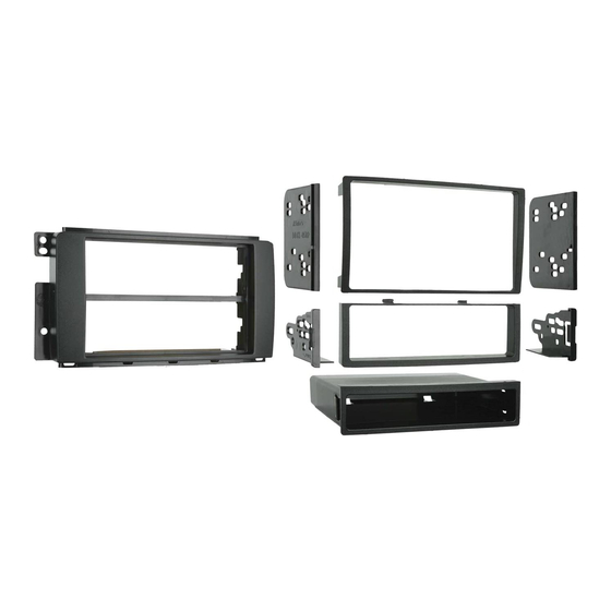
KIT COMPONENTS
• A) Radio Housing • B) ISO Trim Plate • C) ISO Brackets • D) DDIN Trim Plate
• E) DDIN Brackets • F) Pocket
A
WIRING & ANTENNA CONNECTIONS (Sold Separately)
• 70-7903T - Mazda Service T-harness 2007-up
• 40-HD10 - Antenna Adapter
Panel Removal Tool • Phillips Screwdriver • Small Flat Blade Screwdriver
APPLICATIONS
Mazda CX7 2010-up
99-7520B
B
E
TOOLS REQUIRED
METRA. THE WORLD'S BEST KITS.™
1-800-221-0932
© COPYRIGHT 2004-2011 METRA ELECTRONICS CORPORATION
C
F
metraonline.com
E
Advertisement

Related Manuals for Metra Electronics 99-7520B


Summary of Contents for Metra Electronics 99-7520B
- Page 1 INSTALLATION INSTRUCTIONS FOR PART 99-7520B APPLICATIONS Mazda CX7 2010-up 99-7520B KIT FEATURES • DIN radio provision with pocket • ISO radio provision with pocket • Double DIN radio provision • Painted matte black to match factory KIT COMPONENTS • A) Radio Housing • B) ISO Trim Plate • C) ISO Brackets • D) DDIN Trim Plate •...
- Page 2 99-7520B Table of Contents Dash Disassembly – Mazda CX7 2010-up Kit Assembly – Kit preparation – DIN head unit provision – ISO DIN head unit provision – Double DIN head unit provision Caution Metra recommends disconnecting the negative battery terminal before beginning any installation.
- Page 3 99-7520B Dash Disassembly 1. Unclip and remove the (2) trim panels from the left and right side of the radio trim panel. (Figure A) 2. Unclip and remove the trim panel surrounding the radio and climate controls. (Figure B) 3. Remove (4) Phillips screws securing the radio.
- Page 4 99-7520B Dash Disassembly 5. Remove (2) Phillips screws securing the hazard switch to the factory radio then separate the front half from the rear half of the switch to remove. (Figure D) Continue to kit preparation BACK OF FACTORY RADIO...
-
Page 5: Kit Preparation
Kit preparation 99-7520B Kit preparation 1. Secure the hazard switch into the 99- 7520 radio housing using the factory hardware. (Figure a) Continue to kit assembly (Figure A) -
Page 6: Din Head Unit Provision
Kit Assembly 99-7520B DIN head unit provision 1. Locate the factory wiring harness in the dash. Metra recommends using the proper mating adapter from Metra or AXXESS. Re-connect the negative battery terminal and test the unit for proper operation. 2 Slide the DIN cage into the radio housing and secure by bending the metal locking tabs down. -
Page 7: Iso Din Head Unit Provision
Kit Assembly 99-7520B ISO DIN head unit provision 1. Locate the factory wiring harness in the dash. Metra recommends using the proper mating adapter from Metra or AXXESS. Re-connect the negative battery terminal and test the unit for proper operation. -
Page 8: Double Din Head Unit Provision
Kit Assembly 99-7520B Double DIN head unit provision 1. Locate the factory wiring harness in the dash. Metra recommends using the proper mating adapter from Metra or AXXESS. Re-connect the negative battery terminal and test the unit for proper operation. - Page 9 Notes...
- Page 10 Notes...
- Page 11 Notes...
- Page 12 INSTALLATION INSTRUCTIONS FOR PART 99-7520B METRA. THE WORLD’S BEST KITS.™ metraonline.com 1-800-221-0932 © COPYRIGHT 2004-2011 METRA ELECTRONICS CORPORATION...
Need help?
Do you have a question about the 99-7520B and is the answer not in the manual?
Questions and answers