Table of Contents
Advertisement
Quick Links
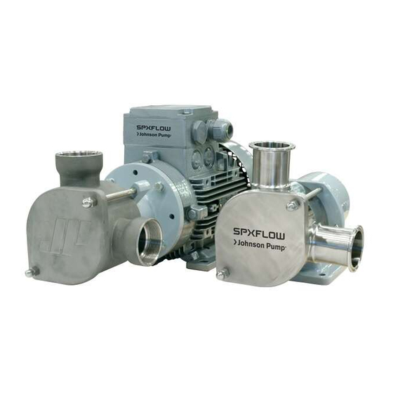
FIP - series
f l e x i b l e i m p e l l e r p u m p s
A . 010 0 . 3 01 – i m - f i p / 0 8 . 0 0 e N ( 0 2 / 2 014 )
r e V i s i O N : 0 8 . 0 0
O r i G i N A l i N s T r u CT i O N s / T r A N s l AT i O N O f O r i G i N A l i N s T r u CT i O N s
r e A D A N D u N D e r s TA N D T H i s m A N uA l p r i O r TO O p e r AT i N G O r s e r V i C i N G T H i s p r O D u CT.
i N s T r u CT i O N m A N uA l
Advertisement
Table of Contents

Related Manuals for SPX FIP - series


Summary of Contents for SPX FIP - series
- Page 1 N s T r u CT i O N m A N uA l FIP - series f l e x i b l e i m p e l l e r p u m p s A . 010 0 . 3 01 – i m - f i p / 0 8 . 0 0 e N ( 0 2 / 2 014 ) O r i G i N A l i N s T r u CT i O N s / T r A N s l AT i O N O f O r i G i N A l i N s T r u CT i O N s r e V i s i O N : 0 8 .
- Page 2 EC-Declaration of conformity Machinery Directive 2006/42/EC, Annex IIA manufacturer SPX Flow Technology Sweden AB P.O. Box 1436 SE-701 14 Örebro, Sweden We hereby guarantee that fip-range – flexible impeller pumps are in conformity with the relevant provisions of the Machinery Directive 2006/42/EC, Annex I.
-
Page 3: Table Of Contents
Contents Introduction ...................5 1.1 General ....................5 1.2 Reception, handling and storage .............5 1.2.1 Reception ...................... 5 1.2.2 Handling ......................5 1.2.3 Storage......................6 1.3 Safety ......................6 1.3.1 General......................6 1.3.2 Pump units..................... 7 1.3.2.1 Pump unit handling ....................7 1.3.2.2 Installation ......................... - Page 4 Installation, operation and maintenance ......20 3.1 Pumping of foodstuffs ..............20 3.2 Pumping of corrosive liquids ............20 3.3 Installation and piping ..............20 3.4 Starting up ..................21 3.5 Frequent check points ..............21 Disassembly and assembly ............ 22 4.1 Assembly of head kit (pump without motor) to IEC-motor ..
-
Page 5: Introduction
The manufacturing code, e.g. 9707, states the year and week of production. Nameplate Bronze and Industrial pumps Nameplate Hygienic pumps SPX Flow Technology Sweden AB SPX Flow Technology Sweden AB Örebro, Sweden, Tel. +46 (0)19 21 83 00 Örebro, Sweden, Tel. +46 (0)19 21 83 00 www.spx.com... -
Page 6: Storage
1.2.3 Storage A pump which is not installed immediately should be stored in a cool and dark room and the impeller should be removed. The rubber material of the impeller ages and should be treated as perishables. The storage should not exceed 2 years. If the pump has been out of operation for a longer period of time, the impeller should be greased (for foodstuff applications use appropriate food grease) before use to obtain optimal suction ability. -
Page 7: Pump Units
1.3.2 Pump units 1.3.2.1 pump unit handling Use an overhead crane, forklift or other suitable lifting device Secure lifting slings around the front part of the Warning pump and the back part of the motor. Make sure Never lift the pump unit with only one fastening that the load is balanced before attempting the point. -
Page 8: Before Commissioning The Pump Unit
When changing the operating conditions of the pump please contact your supplier to ensure a safe and reliable working pump. SPX Flow Technology Sweden AB Örebro, Sweden, Tel. +46 (0)19 21 83 00 www.spx.com www.johnson-pump.com This also applies to modifications on a larger scale,... -
Page 9: Function And Operating Principle
1.4 Function and operating principle The impeller pump is designed for circulation, transport, emptying, filtration and dosing of liquids. The pumps are self-priming. The suction capacity is related to speed, viscosity and pipe dimension. An untight suction pipe will reduce the suction capacity considerably. The impeller pump can handle both high and low viscous liquids as well as liquids containing solid particles, air and gases. -
Page 10: Model Specifications
1.5 Model Specifications Example: 20 SH – 2 M01 P80 1. family name Flexible Impeller Pump 2. pump size Average inlet and outlet port diameter, mm See dimensional drawings, section 6.0 3. material of pump body and cover Stainless steel, hygienic version Stainless steel, industrial version Bronze 4. - Page 11 Example: 20 SH – 2 M01 P80 6. shaft Bronze Splines – Stainless steel Stainless steel pumps Splines – Stainless steel Double flat – Stainless steel 7. shaft seals Single mechanical seal Lip seal Material of single mechanical seals Carbon/ceramic/nitrile Silicon carbide/silicon carbide/FPM (DIN/ISO) / FKM (ASTM) (on request only) FDA Approved mechanical seal...
-
Page 12: Impeller Data
1.6 Impeller data 1.6.1 Pump sizes FIP20S – FIP65S pump impeller impeller min. start min. reverse max. head Hub type impeller material suction size code torque (Nm) torque (Nm) (bar) lift dry (m) FIP20S 832S-7 Double flat EPDM, FDA, Food FIP20S 833S-4 Double flat... -
Page 13: Capacity Range Fip20S - Fip65S
1.6.3 Capacity range FIP20S – FIP65S Neoprene/EPDM high pressure impellers – Curves based on water at 20°C fip-range at 1450 rpm FIP20 FIP25 FIP40 FIP65 FIP50 l/min fip-range at 900 rpm FIP25 FIP40 FIP20 FIP65 FIP50 l/min fip-range at 700 rpm FIP25 FIP40 FIP65... -
Page 14: Capacity Range Fip25B
1.6.4 Capacity range FIP25B 1.6.4.1 Neoprene standard pressure impellers – Curves based on water at 20°C 2,000 rpm 2,500 rpm 2,800 rpm 3,000 rpm 1,400 rpm 900 rpm 700 rpm 500 rpm l/min 1.6.4.2 Neoprene high pressure impellers – Curves based on water at 20°C 2,000 rpm 1,400 rpm 700 rpm... -
Page 15: Capacity Range Fip40B
1.6.5 Capacity range FIP40B 1.6.5.1 Neoprene standard pressure impellers – Curves based on water at 20°C 1,400 rpm 2,000 rpm 2,500 rpm 900 rpm 700 rpm 500 rpm 250 rpm 100 rpm l/min F l o w ( l i t / m i n ) 1.6.5.2 Neoprene high pressure impellers –... -
Page 16: Technical Information
2.0 Technical information Important! The pump must not be used for other applications than recommended and quoted for without consulting your supplier. 2.1 Dry running Thanks to the self-priming ability of the pump it will only take a few seconds before the pump starts to prime. -
Page 17: Shaft Seals
2.4 Shaft seals 2.4.1 Mechanical seals Recommended for foodstuffs, solvents and heavier chemicals. Only FDA mechanical seals are approved for food applications. Delivered as standard with seal surfaces in carbon vs ceramic. The mechanical seal for hygienic stainless steel pumps are supplied with an extra O-ring to seal off the area behind the stationary seal part. -
Page 18: Liquid Temperature And Impeller Life
2.5.1 Liquid temperature and impeller life The service life indicated below is based on several tests with water at 20°C at continuous duty. Continuous duty will not effect the service life of the impeller, but in installations with frequent change of rotation, the service life of the impellers will decrease. Neoprene end EPDM • Temperature range +3°... -
Page 19: Pressure
2.8 Pressure The pump may not be operating above its performance - see max pressure, etc. see section 1.6. If the pump is operating above these data, there will be a risk of shaft breakage, leaking shaft seal, impeller breakage or total wreckage of the pump. Max recommended inlet pressure is 0.5 bar. -
Page 20: Installation, Operation And Maintenance
3.0 Installation, operation and maintenance Note! See also section 1.3 Safety. 3.1 Pumping of foodstuffs When pumping foodstuffs and other liquids with hygienic demands, the pump and the system must always be drained and cleaned after every use. 3.2 Pumping of corrosive liquids Corrosive and sometimes even relatively neutral liquids will attack the material of pump and pump system. -
Page 21: Starting Up
3.4 Starting up • Make sure that all valves are open. • Check that all safety devices are in place, e.g. coupling guards, lockable circuit breakers and other safety guards keeping personnel from coming into contact with the rotating parts of the unit. • Check the rotation of the pump by turning the pump on briefly once. -
Page 22: Disassembly And Assembly
4.0 Disassembly and assembly 4.1 Assembly of head kit (pump without motor) to IEC-motor See drawing sections 5.1 and 5.5. 1) Clean the motor shaft and make sure that the surface does not have any cuts or marks. 2) Put the pump and motor shaft together by using a plastic hammer or equivalent. Make sure not to damge the pump shaft. -
Page 23: Disassembly Of Pedestal
3) Assemble the pump body to the pedestal/ flange, taking care not to damage the seal. 4) Lubricate the impeller with grease or vaseline. For foodstuff applications use appropriate food grease. Push the impeller into the pump body with a twisting movement in the operating direction, centralizing the impeller hub. -
Page 24: Sectional Drawings And Spare Part Lists
5.0 Sectional drawings and Spare part lists 5.1 Drawing – Bronze pumps (B) – Flange mounted A.0100.301 – IM-FIP/08.00 EN (02/2014) -
Page 25: Spare Part List - Fip25B And Fip40B - Flange Mounted
5.2 Spare part list FIP25B and FIP40B – Flange mounted Drawing: Page 24 fip25b fip40b Description Version*) 10-45874 10-45880 Cap screw (front cover) 01-46505 01-46505 Front cover 01-45781 01-45778 Impeller - Neoprene 09-1028B 09-819B Impeller - Neoprene, high pressure – –... -
Page 26: Drawing - Bronze Pumps (B) - Pedestal Mounted
5.3 Drawing – Bronze pumps (B) – Pedestal mounted A.0100.301 – IM-FIP/08.00 EN (02/2014) -
Page 27: Pedestal Mounted
5.4 Spare part list FIP25B and FIP40B – Pedestal mounted Drawing: Page 26 fip25b fip40b Description Version*) 10-45875 10-45881 Cap screw (front cover) 01-46505 01-46505 Front cover 01-45781 01-45778 Impeller - Neoprene 09-1028B 09-819B Impeller - Neoprene, high pressure 09-816B 09-818B Impeller - Nitrile 09-1028B-9... -
Page 28: Drawing - Stainless Steel Pumps (S) - Flange Mounted
5.5 Drawing – Stainless steel pumps (S) – Flange mounted A.0100.301 – IM-FIP/08.00 EN (02/2014) -
Page 29: Flange Mounted
5.6 Spare part list FIP20S, FIP25S, FIP40S, FIP50S – Flange mounted Drawing: Page 28 fip20si/sH fip25si/sH fip40si/sH fip50si/sH Description Version *) 10-13211 si 10-13212 si 10-13214 si 10-13218 si 10-13210 sH 10-13213 sH 10-13215 sH 10-13216 sH Cap screw (cover) 01-46505 01-46505 01-46505... -
Page 30: Drawing - Stainless Steel Pumps (S) - Pedestal Mounted
Drawing – Stainless steel pumps (S) – Pedestal mounted A.0100.301 – IM-FIP/08.00 EN (02/2014) -
Page 31: Pedestal Mounted
5.8 Spare part list FIP20S, FIP25S, FIP40S, FIP50S, FIP65S – Pedestal mounted Drawing: Page 30 fip20si/sH fip25si/sH fip40si/sH fip50si/sH fip65si/sH Description Version *) 10-24544 si 10-24546 si 10-24548 si 10-13219 si 10-13220 si 10-24543 sH 10-24545 sH 10-24547 sH 10-13217 sH 10-13221 sH Cap screw (cover) 01-46505... -
Page 32: Dimensions And Weights
6.0 Dimensions and weights 6.1 FIP25B and FIP40B – Flange and Pedestal mounted bronze Version – flange ieC- Weight, kg motor size pump+motor, FIP25B 80 68 ø10 125 140 140 126 ø38 BSP 1" / 12.8 NPTF 1" FIP40B 90 85 ø10 140 165 167 ø63 BSP 1.1/2"... -
Page 33: Fip20S-Fip65S - Flange Mounted
6.2 FIP20S-FIP65S – Flange mounted stainless steel industrial Version – flange stainless steel Hygienic Version – flange FIP20SI – – – ø10 ø31.8 FIP20SH 80 75.5 ø10 ø22.2 FIP25SI – – – ø10 ø38 FIP25SH 80 ø10 ø25 FIP40SI – –... -
Page 34: Fip20S-Fip65S - Pedestal Mounted
6.3 FIP20S-FIP65S – Pedestal mounted stainless steel industrial Version – pedestal stainless steel Hygienic Version – pedestal FIP20SI – – – 2.5 ø9 40 41 30 48 200 50 ø31.8 FIP20SH 75.5 2.5 ø9 40 41 30 48 200 50 ø22.2 FIP25SI –... -
Page 35: Trouble Shooting Chart
7.0 Trouble shooting chart Pump Cause remedy Pump is not starting No electric power Check/replace the fuse. Check that the electric system is not overloaded. Low voltage Check that the wiring is not too long and that it has the right dimension. Unsufficient starting torque of motor Check starting torque required, change the motor if necessary... - Page 36 Cause remedy Pump is leaking Pressure too high Decrease pressure by increasing the diameter of the pipings and also on any filters installed. Clean filter if installed Worn shaft seal Replace shaft seal Worn ball bearings, shaft deflection Replace ball bearings Common reasons for unnormal wear of the Contact your supplier for further advice.
-
Page 37: Impeller
Impeller This guide is designed to help you to identify typical application problems that now and then occur in flexible impellers during normal use. Rubber is a “living” material and impellers should be kept in a dark and cool place for long term storage. - Page 38 problem 4 Vanes permanently and excessively curved. Causes Long term storage in pump. Normal end of useful life. (Especially for Nitrile impellers.) Precautions Always remove the impeller for long term storage. Keep it in a dark and cool place. Refit the impeller to rotate in opposite direction.
- Page 39 ”Johnson Pump” and the stylized JP logo are registered trademarks of SPX Corporation...
- Page 40 Fax: +46 (0)19 27 23 72 Email: johnson-pump.se.support@spx.com SPX reserves the right to incorporate our latest design and material changes without notice or obligation. Design features, materials of construction and dimensional data, as described in this bulletin, are provided for your information only and should not be relied upon unless confirmed in writing.