Table of Contents
Advertisement
SPX Bolting Systems
Unit 4, Wansbeck Business Park
Rotary Parkway
Ashington
Northumberland NE63 8QW
spxboltingsystems.com
Original Instructions
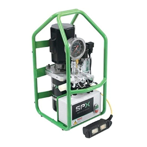
Compact Torque Wrench Pump
© SPX
Tel: +44 (0) 1670 850580
Fax: +44 (0) 1670 850655
PE39 Series
Operating Instructions for:
PE39PED1BPR
PE39PED1PR
PE39YED1BPR
PE39YED1PR
Form No. 1000542
Rev. 2 November 14, 2014
Advertisement
Table of Contents

Related Manuals for SPX PE39 Series


Summary of Contents for SPX PE39 Series
- Page 1 Operating Instructions for: PE39PED1BPR PE39PED1PR PE39YED1BPR SPX Bolting Systems Tel: +44 (0) 1670 850580 Unit 4, Wansbeck Business Park Fax: +44 (0) 1670 850655 PE39YED1PR Rotary Parkway Ashington Northumberland NE63 8QW spxboltingsystems.com Original Instructions PE39 Series Compact Torque Wrench Pump Form No.
-
Page 2: Table Of Contents
Declaration of Conformity ..........31 Form No. 1000542 Rev. 2 November 14, 2014 © SPX... -
Page 3: Description
Description: The PE39 series hydraulic pump is designed to have a maximum of 690 bar (10,000 psi) at a flow rate of 639 cc/min (39 cu. in/min). All pumps come fully assembled and ready for work. Compact Electric/Hydraulic Torque Wrench Pumps... -
Page 4: Control Valves
Switch Cylinder Type Equipped with 0.8 kW (1.04 HP Remote See Figure Hydraulic 2002108 2-position/4-way average) 50/60 Hz, motor 3. SPX torque wrench 2-position/4-way, solenoid valve. nominal 115 VAC, Part No. pump mounted, single-phase 3000554 solenoid operated Valve Function Diagrams Advance Position: (Solenoid "A") Pressure to "A"... -
Page 5: Safety Symbols And Definitions
• Retract the system before adding fluid to prevent overfilling the pump reservoir. An overfill can cause personal injury due to excess reservoir pressure created when tools are retracted. Form No. 1000542 Rev. 2 November 14, 2014 © SPX... - Page 6 Hoses also must not come in contact with corrosive material such as creosote- impregnated objects and some paints. Consult the manufacturer before painting a hose. Never paint the couplers. Hose deterioration due to corrosive materials may result in personal injury. Form No. 1000542 Rev. 2 November 14, 2014 © SPX...
- Page 7 Any loose pieces of tape could travel through the system and obstruct the flow of fluid or cause jamming of precision-fit parts. Form No. 1000542 Rev. 2 November 14, 2014 © SPX...
-
Page 8: Initial Setup
3. See Figure 3. Remove the protective covers from the hydraulic fluid outlets. 4. Connect the hose assembly to the hydraulic fluid outlet, and couple the hose to the tool. Figure 3. Hydraulic Fluid Outlets Form No. 1000542 Rev. 2 November 14, 2014 © SPX... - Page 9 3. Start the pump and shift as required. 4. Turn off the pump when not in use. 5. Disconnect the motor control pendant. 6. See Figure 6. Disconnect power source. Figure 6. Disconnected from Power Source Form No. 1000542 Rev. 2 November 14, 2014 © SPX...
- Page 10 Check the reservoir fluid level and fill to correct level with Power Team hydraulic fluid as necessary. If there is a problem contact Hydraulic Technologies Technical Support. To locate a Power Team Authorized Hydraulic Service Center, contact your nearest Hydraulic Technologies facility or www.SPXBOLTINGSYSTEMS.com. Form No. 1000542 Rev. 2 November 14, 2014 © SPX...
-
Page 11: Operating Instructions
Description switch to IDLE allows hydraulic fluid to cycle through OFF Position the pump back to the tank. ON Position Idle Position Retract Position Advance Position Figure 9. Pendant Control Form No. 1000542 Rev. 2 November 14, 2014 © SPX... - Page 12 6. Using the pendant press the ON/OFF rocker switch to OFF. 7. Press the OFF (red) switch on the control box. Figure 10. Pressure Regulating Valve Form No. 1000542 Rev. 2 November 14, 2014 © SPX...
-
Page 13: Performance Specifications
690 Bar (1,000 PSI) (5,000 PSI) (10,000 PSI) PE39 690 (10,000) 0.90 (55) 0.80 (49) 0.64 (39) * Typical delivery. Actual flow varies with field conditions. Table 4. Fluid Pressure Chart Form No. 1000542 Rev. 2 November 14, 2014 © SPX... -
Page 14: General Maintenance
The frequency of fluid changes depends upon general working conditions, severity of use, the overall cleanliness and care given to the pump. Fluid should be changed more frequently when the system is not operated regularly indoors. Form No. 1000542 Rev. 2 November 14, 2014 © SPX... - Page 15 Store the unit in a dry, well-protected area where it will not be exposed to corrosive vapors, dust, or other harmful elements. If a unit has been stored for an extended period of time, it must be thoroughly inspected before it is used. Form No. 1000542 Rev. 2 November 14, 2014 © SPX...
- Page 16 8. See Figure 14. Disconnect power cord from power source. Figure 14. Disconnected from Power Source 9. See Figure 15. Loosen the screw clamp. Figure 15. Screw Clamp Form No. 1000542 Rev. 2 November 14, 2014 © SPX...
- Page 17 47 cSt @ 38°C (215 SUS @ 100°F) If low temperature requirements are needed, use hydraulic oil 5.1 cSt @ 100°C (451 cSt @ -40°C). Figure 18. Inlet Suction Filter Form No. 1000542 Rev. 2 November 14, 2014 © SPX...
- Page 18 Removal and Installation. Figure 20. Disconnected from Power Source 3. See Figure 21. Use a screwdriver to remove the brush holder cap. 4. Remove the brush. Figure 21. Brush Holder Form No. 1000542 Rev. 2 November 14, 2014 © SPX...
- Page 19 6. See Figure 23. Install brush assemblies and brush holder caps. Figure 23. Brush Fuse Replacement 1. See Figure 24. Disconnect power cord from power source. Figure 24. Disconnected from Power Source Form No. 1000542 Rev. 2 November 14, 2014 © SPX...
- Page 20 3. Replace the fuse. On 115V (nominal) replace 15A time delay 250VAC 5x20mm fuse , 230V (nominal) replace 10A time delay 250VAC 5x20mm fuse. 4. To install, reverse the removal procedure. Figure 25. External Fuse Holder Form No. 1000542 Rev. 2 November 14, 2014 © SPX...
-
Page 21: Troubleshooting Guide
Pump delivers excess fluid 1. Faulty pressure gauge. 1. Replace gauge. pressure. 2. Relief valve set incorrectly. 2. Contact a Hydraulic Technologies Service Center. Form No. 1000542 Rev. 2 November 14, 2014 © SPX... - Page 22 3. Attached component sticking or 3. Refer to manufacture's binding. information for attached component. 4. Malfunctioning valve. 4. Verify connections. Contact authorized Hydraulic Technologies Service Center. Form No. 1000542 Rev. 2 November 14, 2014 © SPX...
-
Page 23: Repair Procedures
2. See Figure 27. Remove the three motor shroud screws. Figure 27. Motor Shroud Screws 3. See Figure 28. Remove the two electric shroud screws and remove the motor shroud. Figure 28. Electric Shroud Screws Form No. 1000542 Rev. 2 November 14, 2014 © SPX... - Page 24 5. See Figure 30. If necessary, disconnect the three wires from the motor. Figure 30. Motor Wires 6. See Figure 31. If necessary, remove the nut and route the wires through the electrical shroud. Figure 31. Cover Nut Form No. 1000542 Rev. 2 November 14, 2014 © SPX...
- Page 25 M6 bolt and install the bolt. Verify wires are not pinched or contacting the armature. Torque to 4.5-5 Nm (40-45 in/lbs). Figure 34. Electric Shroud Screw Form No. 1000542 Rev. 2 November 14, 2014 © SPX...
- Page 26 11. See Figure 37. Apply a small amount of Loctite® 243 or equivalent on end of the M6 bolt and install the bolt. Torque to 3.3-3.9 Nm (30-35 in/lbs). Figure 37. Motor Shroud Screw Form No. 1000542 Rev. 2 November 14, 2014 © SPX...
- Page 27 4. See Figure 39. Loosen but do not remove the four electrical box screws. Position the cover aside. Figure 39. Cover Screws 5. See Figure 40. Remove the four electrical box screws. Figure 40. Mounting Screws Form No. 1000542 Rev. 2 November 14, 2014 © SPX...
- Page 28 8. If necessary, remove the worm clamp. 9. To install, reverse the removal procedure. 10. Install bolts and tighten to 7.5 Nm (65 in/lbs). Figure 42. Motor Bolts Form No. 1000542 Rev. 2 November 14, 2014 © SPX...
-
Page 29: Parts List
Parts List Item Part Req'd Description Notes 9072 GAUGE, 10000 PSI, 4" DIA, CAL. (SPX) 3000556 ASSY, PUMP/MOTOR (110/115V 50/60Hz) 3000584 ASSY, PUMP/MOTOR (220/230V 50/60Hz) 2002095 MOTOR SHROUD KIT 1000371 DECAL, BURN HAZARD/HOT SURFACE. ISO G1-1074-27 O-RING (NOT SHOWN) 1000550 DECAL, TANK FILL LINE Form No. - Page 30 DECAL, PLAS CERT CE US RECT 2.24 IN 1000608 DECAL, PLAS INFO CAUT US RECT 3.0 IN 1000543 DECAL, SPX BOLTING SYSTEMS DECAL, PLAS CERT CE US RECT 4.75 IN 1000616 (PE39YED1PR) DECAL, PLAS CERT CE US RECT 4.75 IN...
-
Page 31: Hydraulic Technologies Facilities
Hydraulic Technologies Facilities UNITED ST ATES CHINA EUROPE C E R T I F I E D SPX Hydraulic Technologies Albert Thijsstraat 12 No. 1568 Hua Shan Road 6471 WX Eygelshoven International Park Center 5885 11th Street Shanghai 200052, China... -
Page 32: Declaration Of Conformity
Declaration of Conformity Form No. 1000542 Rev. 2 November 14, 2014 © SPX...
Need help?
Do you have a question about the PE39 Series and is the answer not in the manual?
Questions and answers