Table of Contents
Advertisement
Quick Links
®
Advanced Test Equipment Rentals
www.atecorp.com 800-404-ATEC (2832)
ASX SERIES
AC POWER SOURCE
OPERATION
MANUAL
PACIFIC
POWER SOURCE
Schulz-Electronic GmbH
Dr.-Rudolf-Eberle-Straße 2
D-76534 Baden-Baden
Fon +49.7223.9636.30
Fax +49.7223. 9636.90
vertrieb@schulz-electronic.de
www.schulz-electronic.de
Advertisement
Table of Contents

Subscribe to Our Youtube Channel
Related Manuals for Pacific Power Source ASX series


Summary of Contents for Pacific Power Source ASX series
- Page 1 ® Advanced Test Equipment Rentals www.atecorp.com 800-404-ATEC (2832) ASX SERIES AC POWER SOURCE OPERATION MANUAL PACIFIC POWER SOURCE Schulz-Electronic GmbH Dr.-Rudolf-Eberle-Straße 2 D-76534 Baden-Baden Fon +49.7223.9636.30 Fax +49.7223. 9636.90 vertrieb@schulz-electronic.de www.schulz-electronic.de...
- Page 3 THE INFORMATION CONTAINED IN THIS MANUAL IS PROPRIETARY TO PACIFIC POWER SOURCE. AND MAY NOT BE COPIED OR REPRINTED WITHOUT ITS EXPRESSED WRITTEN CONSENT. PACIFIC POWER SOURCE, INC. 17692 Fitch Irvine, CA 92614 FIFTH EDITION COPYRIGHT (C) PPS MARCH, 2010...
-
Page 4: Limited Warranty
FROM THE FACTORY. LIMITED WARRANTY Pacific Power Source (PPS) warrants each unit to be free from defects in material and workmanship. For the period of two (2) years from the date of shipment to the purchaser, PPS will either repair or replace, at its sole discretion, any unit returned to its factory in Irvine, California. -
Page 5: Table Of Contents
TABLE OF CONTENTS PAGE GENERAL ............................1 USING THIS MANUAL ......................... 1 SAFETY NOTICES ........................2 GENERAL PRODUCT DESCRIPTION ..................4 SPECIFICATIONS ..........................7 ELECTRICAL SPECIFICATIONS ....................7 2.1.1 INPUT POWER REQUIREMENTS ..................7 2.1.2 OUTPUT POWER ....................... 12 2.1.3 OUTPUT POWER FACTOR .................... - Page 6 TABLE OF CONTENTS PAGE CONNECTION OF SYSTEM CONTROL UNIT (SCU) ..............67 REMOTE INTERFACE ........................ 69 AUX I/O INSTALLATION ......................69 EXTERNAL SENSE CONNECTION .................... 70 OPERATION ............................73 FRONT PANEL CONTROLS ....................... 73 INITIAL POWER-UP ........................75 ROUTINE POWER-UP ........................ 76 SYSTEM TURN-OFF ........................
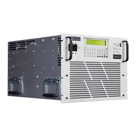
- Page 7 LIST OF ILLUSTRATIONS PAGE FIGURE1.3 ASX-SERIES POWER SOURCE - FRONT VIEW ............6 FIGURE 2.1.2 (A) MODEL 115-ASX OUTPUT DERATING CURVES ........... 13 FIGURE 2.1.2 (B) MODEL 120-ASX OUTPUT DERATING CURVES ............ 14 FIGURE 2.1.2 (C) MODEL 140-ASX OUTPUT DERATING CURVES ........... 15 FIGURE 2.1.2 (D) MODEL 160-ASX OUTPUT DERATING CURVES ...........
-
Page 9: General
GENERAL This manual provides information required to use an ASX-Series AC Power Source. Operation of the ASX series models: 115-ASX, 120-ASX, 140-ASX, 160-ASX, 315-ASX, 320-ASX, 345-ASX, 360-ASX, and 3120-ASX is described in this document. This is a general Operations Manual. Installation, operation, and calibration are the subjects covered. -
Page 10: Safety Notices
SECTION 1 GENERAL SAFETY NOTICES The ASX-Series equipment is capable of transferring very large amounts of electrical energy very quickly. This basic quality is fundamental to a high-performance power source. The warnings and cautions listed below should be observed at all times. WARNINGS are conditions which are hazardous to user personnel. - Page 11 SECTION 1 GENERAL SAFETY NOTICES (cont.) WARNING IF THIS EQUIPMENT IS NOT USED IN A MANNER SPECIFIED BY THE MANUFACTURER, THE PROTECTION PROVIDED BY THE EQUIPMENT MAY BE IMPAIRED CAUTION READ SECTIONS 1, 3, AND 4 OF THIS MANUAL BEFORE INSTALLING OR OPERATING THIS EQUIPMENT.
-
Page 12: General Product Description
SECTION 1 GENERAL GENERAL PRODUCT DESCRIPTION The ASX-Series Power Source is high-performance AC power conversion equipment. This series of equipment features models with power ratings from 1.5 kVA to 12.0 kVA. All systems are designed to fit into a standard 19 inch instrument rack. The power sources are suitable for use as frequency converters as well as sophisticated AC test power systems. - Page 13 SECTION 1 GENERAL GENERAL PRODUCT DESCRIPTION (cont.) Model 345-ASX - 4.5 kVA model, capable of 1, 2, or 3 Phase operation. Single and three phase modes provide 4.5kVA of power with a 0-135 VAC output voltage range. 2 phase mode provides 3.0kVA of power with a 0-270 voltage range.
-
Page 14: Figure1.3 Asx-Series Power Source - Front View
W/ UPC1 CONTROLLER ON / AUTO OUTPUT POWER OUTPUT DIRECT COUPLING INPUT TRANSFORMER POWER OUTPUT 1 PHASE FORM 2 PHASE 3 PHASE PACIFIC POWER SOURCE INC. IRVINE, CALIFORNIA MODEL 3210-ASX W/ UPC3 CONTROLLER FIGURE1.3 ASX-SERIES POWER SOURCE - FRONT VIEW... -
Page 15: Specifications
SECTION 2 SPECIFICATIONS SPECIFICATIONS This section states the electrical specifications of the ASX-Series Power Source. specifications listed apply to all models, except as noted. Some specifications are controller dependent. These are noted as such. ELECTRICAL SPECIFICATIONS 2.1.1 INPUT POWER REQUIREMENTS This paragraph lists and defines the input voltage forms that are accepted by the various models within the ASX-Series line of equipment. - Page 16 SECTION 2 SPECIFICATIONS 2.1.1 INPUT POWER REQUIREMENTS (cont.) MODEL 120-ASX INPUT VOLTAGE The Model 120-ASX accepts one of the following single phase input voltages: 100 VAC ±10%, 47-63 Hz 110 VAC ±10%, 47-63 Hz 120 VAC ±10%, 47-63 Hz 200 VAC ±10%, 47-63 Hz 208 VAC ±10%, 47-63 Hz 220 VAC ±10%, 47-63 Hz 230 VAC ±10%, 47-63 Hz...
- Page 17 SECTION 2 SPECIFICATIONS 2.1.1 INPUT POWER REQUIREMENTS (cont.) MODEL 160-ASX INPUT VOLTAGE The Model 160-ASX accepts one of the following three phase input voltages: 208 VAC Δ ±10%, 47-63 Hz 220 VAC Δ ±10%, 47-63 Hz 240 VAC Δ ±10%, 47-63 Hz 220/380 VAC ±10%, 47-63 Hz 230/400 VAC ±10%, 47-63 Hz 240/416 VAC ±10%, 47-63 Hz...
- Page 18 SECTION 2 SPECIFICATIONS 2.1.1 INPUT POWER REQUIREMENTS (cont.) MODEL 320-ASX INPUT VOLTAGE The Model 320-ASX accepts one of the following single phase input voltages: 100 VAC ±10%, 47-63 Hz 110 VAC ±10%, 47-63 Hz 120 VAC ±10%, 47-63 Hz 200 VAC ±10%, 47-63 Hz 208 VAC ±10%, 47-63 Hz 220 VAC ±10%, 47-63 Hz 220 VAC ±10%, 47-63 Hz...
- Page 19 SECTION 2 SPECIFICATIONS 2.1.1 INPUT POWER REQUIREMENTS (cont.) MODEL 360-ASX INPUT VOLTAGE The Model 360-ASX accepts one of the following three phase input voltages: 208 VAC Δ ±10%, 47-63 Hz 220 VAC Δ ±10%, 47-63 Hz 240 VAC Δ ±10%, 47-63 Hz 220/380 VAC ±10%, 47-63 Hz...
-
Page 20: Output Power
SECTION 2 SPECIFICATIONS 2.1.2 OUTPUT POWER OUTPUT VOLTAGE RANGE DIRECT-COUPLED The standard output voltage ranges of the ASX-Series are: 0-132 VAC for the Models 115-ASX, 160-ASX, 315-ASX, and 360-ASX; 0-135 VAC for the Models 140-ASX, 345-ASX, and 3120-ASX; and 0-150 VAC for the Models 120-ASX and 320-ASX, when operated in the direct-coupled mode. -
Page 21: Figure 2.1.2 (A) Model 115-Asx Output Derating Curves
SECTION 2 SPECIFICATIONS 2.1.2 OUTPUT POWER ( cont. ) FIGURE 2.1.2 (A) MODEL 115-ASX OUTPUT DERATING CURVES... -
Page 22: Figure 2.1.2 (B) Model 120-Asx Output Derating Curves
SECTION 2 SPECIFICATIONS 2.1.2 OUTPUT POWER ( cont. ) FIGURE 2.1.2 (B) MODEL 120-ASX OUTPUT DERATING CURVES... -
Page 23: Figure 2.1.2 (C) Model 140-Asx Output Derating Curves
SECTION 2 SPECIFICATIONS 2.1.2 OUTPUT POWER ( cont. ) FIGURE 2.1.2 (C) MODEL 140-ASX OUTPUT DERATING CURVES... -
Page 24: Figure 2.1.2 (D) Model 160-Asx Output Derating Curves
SECTION 2 SPECIFICATIONS 2.1.2 OUTPUT POWER ( cont. ) FIGURE 2.1.2 (D) MODEL 160-ASX OUTPUT DERATING CURVES... -
Page 25: Figure 2.1.2 (E) Model 315-Asx Output Derating Curves
SECTION 2 SPECIFICATIONS 2.1.2 OUTPUT POWER ( cont. ) FIGURE 2.1.2 (E) MODEL 315-ASX OUTPUT DERATING CURVES... -
Page 26: Figure 2.1.2 (F) Model 320-Asx Output Derating Curves
SECTION 2 SPECIFICATIONS 2.1.2 OUTPUT POWER ( cont. ) FIGURE 2.1.2 (F) MODEL 320-ASX OUTPUT DERATING CURVES... -
Page 27: Figure 2.1.2 (G) Model 345-Asx Output Derating Curves
SECTION 2 SPECIFICATIONS 2.1.2 OUTPUT POWER ( cont. ) FIGURE 2.1.2 (G) MODEL 345-ASX OUTPUT DERATING CURVES... -
Page 28: Figure 2.1.2 (H) Model 360-Asx Output Derating Curves
SECTION 2 SPECIFICATIONS 2.1.2 OUTPUT POWER ( cont. ) FIGURE 2.1.2 (H) MODEL 360-ASX OUTPUT DERATING CURVES... -
Page 29: Figure 2.1.2 (I) Model 3120-Asx Output Derating Curves
SECTION 2 SPECIFICATIONS 2.1.2 OUTPUT POWER ( cont. ) FIGURE 2.1.2 (I) MODEL 3120-ASX OUTPUT DERATING CURVES... -
Page 30: Output Power Factor
SECTION 2 SPECIFICATIONS 2.1.3 OUTPUT POWER FACTOR The ASX-Series Power Source is designed to operate into any load power factor. However, the derating charts of Figures 2.1.2(A-H) should be consulted for system capabilities at specific output power factors. 2.1.4 OUTPUT FREQUENCY The output frequency range of the ASX-Series Power Source is determined by the controller which is installed in the system. -
Page 31: Output Bandwidth
SECTION 2 SPECIFICATIONS 2.1.8 OUTPUT BANDWIDTH The output bandwidth of the ASX-Series Power Source is listed below. Full Power: 400 Hz (±0.10 db [± 1%]) 1,200 Hz (±0.25 db [± 3%]) Small Signal: 2,500 Hz (±0.5 db [±6%]) ( rated at 10% of full-scale output voltage ) 2.1.9 LOAD TRANSIENT RESPONSE Output load transient response for a 10-90% load induced step transient is approximately 60 μsec. -
Page 32: Mechanical Specifications
SECTION 2 SPECIFICATIONS MECHANICAL SPECIFICATIONS This paragraph describes the mechanical characteristics of the ASX-Series Power Sources. 2.2.1 DIMENSIONS Dimensions of the ASX-Series Power Sources are listed below. MODEL 115-ASX Height: 5.25" [134 mm]; 3 rack unit Width: 19.00" [483 mm] (front panel); 16.75" [426 mm] (chassis) Depth: 23.00"... - Page 33 SECTION 2 SPECIFICATIONS 2.2.1 DIMENSIONS (cont.) MODEL 160-ASX Power Source: Height: 8.75" [222 mm]; 5 rack unit Width: 19.00" [483 mm] (front panel); 16.75" [426 mm] (chassis) Depth: 23.12" [587 mm] (measured from back side of front panel, excludes terminal blocks) Weight: 120 lbs.
- Page 34 SECTION 2 SPECIFICATIONS 2.2.1 DIMENSIONS (cont.) MODEL 345-ASX Power Source: Height: 8.75" [222 mm]; 5 rack unit Width: 19.00" [483 mm] (front panel); 16.75" [426 mm] (chassis) Depth: 23.12" [587 mm] (measured from back side of front panel, excludes terminal blocks) Weight: 125 lbs.
-
Page 35: Input Power Connection
SECTION 2 SPECIFICATIONS 2.2.1 DIMENSIONS (cont.) MODEL 3120-ASX Power Source: Height: 15.75" [401 mm]; 9 rack unit Width: 19.00" [483 mm] (front panel); 17.00" [432 mm] (chassis) Depth: 28.0" [712 mm] Weight: 244 lbs [111 kg] Refer to Figure 2.2.3 for the outline drawing of the Model 3120-ASX. Magnetics Module: Height: 7.00"... -
Page 36: Figure 2.2.1 Outline Drawing, Models 115, 120, 315, & 320-Asx
SECTION 2 SPECIFICATIONS 2.2.2 INPUT POWER CONNECTION ( cont.) U P C 1 P R O G R A M M A B L E C O N T R O L L E R FIGURE 2.2.1 OUTLINE DRAWING, MODELS 115, 120, 315, & 320-ASX... -
Page 37: Figure 2.2.2 Outline Drawing, Models 140,160,345,360-Asx
SECTION 2 SPECIFICATIONS 2.2.2 INPUT POWER CONNECTION ( cont.) U P C 3 P R O G R A M M A B L E C O N T R O L L E R C L E A R H E L P E N T E R P R O G R A M... -
Page 38: Figure 2.2.3 Outline Drawing, Model 3120-Asx
SECTION 2 SPECIFICATIONS 2.2.2 INPUT POWER CONNECTION ( cont.) CONTROLLER INPUT AC CIRCUIT BREAKDER O N / A U T O O U T P U T P O W E R O F F O F F O U T P U T D I R E C T C O U P L I N G T R A N S F O R M E R... -
Page 39: Figure 2.2.4 Outline Drawing, Models 140,160,345 & 360-Asx Magnetics Module
SECTION 2 SPECIFICATIONS 2.2.2 INPUT POWER CONNECTION ( cont.) FIGURE 2.2.4 OUTLINE DRAWING, MODELS 140,160,345 & 360-ASX MAGNETICS MODULE... -
Page 40: Figure 2.2.5 Outline Drawing, Model 3120-Asx Magnetics Module
SECTION 2 SPECIFICATIONS 2.2.2 INPUT POWER CONNECTION ( cont.) FRONT VIEW AIR INTAKE SIDE VIEW AIR INTAKE I/O CONNECTORS EXHAUST AIR REAR VIEW FIGURE 2.2.5 OUTLINE DRAWING, MODEL 3120-ASX MAGNETICS MODULE... -
Page 41: Output Power Connection
The chassis of most ASX-Series Power Source models is designed to accept slide rails. These are provided as a cost option. For more information, contact your local sales representative or the Pacific Power Source Sales Office. ENVIRONMENTAL SPECIFICATIONS The environmental requirements of the ASX-Series Power Sources are: 2.3.1 TEMPERATURE RANGE... -
Page 42: Installation
SECTION 3 INSTALLATION INSTALLATION This section describes the installation of the ASX-Series AC Power Source. CHASSIS PLACEMENT The ASX-Series Power Source is designed to fit into the standard 19 inch rack. Provisions for mounting slide rails are included in most chassis. The ASX can also be used as a bench-top unit, if desired. - Page 43 The front panel alone will not support the weight of the chassis. Chassis slides are available from Pacific Power Source as a cost option. Call factory service for details. After the location for the chassis is selected, verify that the input voltage of the power source is correct (Input voltage is stated on the system ID label).
-
Page 44: Output Voltage Range Configurations
SECTION 3 INSTALLATION OUTPUT VOLTAGE RANGE CONFIGURATIONS This paragraph describes the configuration of the Output Voltage Range for the ASX-Series Power Source. The ASX-Series Power Source can be configured for several different Output Voltage Ranges. The standard output configurations are: 0-132 VAC Direct-Coupled Output, standard on Models 115-ASX, 160-ASX, 315-ASX, and 360-ASX... -
Page 45: Output Voltage Range Configuration, Model 115-Asx
SECTION 3 INSTALLATION 3.2.1 OUTPUT VOLTAGE RANGE CONFIGURATION, MODEL 115-ASX This paragraph describes the configuration of the Output Voltage Range for the Model 115-ASX Power Source. This model can be configured for either 0-132 VAC , 0-198 VAC , 0-264 VAC or 0-330 VAC . -
Page 46: Figure 3.2.1 Model 115-Asx Output Voltage Range Configuration
SECTION 3 INSTALLATION 3.2.2 OUTPUT VOLTAGE RANGE, MODELS 115-ASX ( cont. ) FIGURE 3.2.1 MODEL 115-ASX OUTPUT VOLTAGE RANGE CONFIGURATION... -
Page 47: Output Voltage Range, Models 120-Asx And 320-Asx
SECTION 3 INSTALLATION 3.2.2 OUTPUT VOLTAGE RANGE, MODELS 120-ASX AND 320-ASX The Output Voltage Range for the Models 120-ASX and 320-ASX Power Sources is 0-150 VAC direct-coupled. TRANSFORMER RATIO The Transformer Ratio Setting of the UPC is always set to 0.0 in these models. (Refer to the UPC-Series Operation Manual for details.) AMPS TO VOLTS RATIO The Amps to Volts Ratio Setting of the UPC is always set to 6 in these models. -
Page 48: Figure 3.2.2 Model 315-Asx Output Voltage Range Configuration
SECTION 3 INSTALLATION 3.2.3 OUTPUT VOLTAGE RANGE CONFIGURATION, MODEL 315-ASX ( cont. ) FIGURE 3.2.2 MODEL 315-ASX OUTPUT VOLTAGE RANGE CONFIGURATION... -
Page 49: Output Voltage Range Configuration, Models 140-Asx, 160-Asx, 345-Asx, And 360-Asx
The Transformer Ratio Setting of the UPC is set to 0.0 on systems without transformer-coupled outputs. While the above procedure can be performed in the field, Pacific Power Source recommends that the system be returned to the factory when transformer-coupled outputs are to be added to the... -
Page 50: Figure 3.2.3 Models 140, 160, 345, & 360-Asx Output Voltage Range Configuration
SECTION 3 INSTALLATION 3.2.4 OUTPUT VOLTAGE RANGE CONFIGURATION, MODELS 140-ASX, 160- ASX, 345-ASX, AND 360-ASX ( cont. ) FIGURE 3.2.3 MODELS 140, 160, 345, & 360-ASX OUTPUT VOLTAGE RANGE CONFIGURATION... -
Page 51: Output Voltage Range Configuration, Model 3120-Asx
The Transformer Ratio Setting of the UPC-3 is set to 0.0 on systems without transformer-coupled outputs. While the above procedure can be performed in the field, Pacific Power Source recommends that the system be returned to the factory when transformer-coupled outputs are to be added to the... -
Page 52: Figure 3.2.4 Model 3120-Asx Output Voltage Range Configuration
SECTION 3 INSTALLATION 3.2.5 OUTPUT VOLTAGE RANGE CONFIGURATION, MODEL 3120-ASX ( cont. ) OUTPUT VOLTAGE RANGE CONFIGURATION XFM ER LEAD VR 1.5 VR 2.0 VR 2.5 Tx - 1 TBx - A5 TBx - A5 TBx - A5 Tx - 2 TBx - D6 TBx - C5 TBx - B4... -
Page 53: Input Power Connection
SECTION 3 INSTALLATION INPUT POWER CONNECTION This paragraph describes configuration of input voltage form and requirements of the input wiring for the ASX-Series Power Source. Since each model varies, each is discussed in a separate paragraph. Please refer to the appropriate paragraph for the model being configured. 3.3.1 INPUT VOLTAGE CONFIGURATION, MODEL 115-ASX WARNING DISCONNECT THIS UNIT FROM THE INPUT SERVICE BEFORE REMOVING TOP COVER. -
Page 54: Figure 3.3.1 Model 115-Asx Input Voltage Configuration
SECTION 3 INSTALLATION 3.3.1 INPUT VOLTAGE CONFIGURATION, MODEL 115-ASX ( cont.) FIGURE 3.3.1 MODEL 115-ASX INPUT VOLTAGE CONFIGURATION... -
Page 55: Input Voltage Configuration, Models 120-Asx And 320-Asx
SECTION 3 INSTALLATION 3.3.2 INPUT VOLTAGE CONFIGURATION, MODELS 120-ASX AND 320-ASX WARNING DISCONNECT THIS UNIT FROM THE INPUT SERVICE BEFORE REMOVING TOP COVER. HIGH VOLTAGE HAZARD PRESENT INSIDE UNIT WHEN TOP COVER IS REMOVED AND STILL CONNECTED TO INPUT SERVICE. The 120-ASX and 320-ASX Power Sources have been designed to accept most standard single phase input voltage forms. -
Page 56: Figure 3.3.2 Models 120-Asx And 320-Asx Input Voltage Configuration
SECTION 3 INSTALLATION 3.3.2 INPUT VOLTAGE CONFIGURATION, MODELS 120-ASX AND 320-ASX (cont.) FIGURE 3.3.2 MODELS 120-ASX AND 320-ASX INPUT VOLTAGE CONFIGURATION... -
Page 57: Input Voltage Configuration, Model 315-Asx
SECTION 3 INSTALLATION 3.3.3 INPUT VOLTAGE CONFIGURATION, MODEL 315-ASX WARNING DISCONNECT THIS UNIT FROM THE INPUT SERVICE BEFORE REMOVING TOP COVER. HIGH VOLTAGE HAZARD PRESENT INSIDE UNIT WHEN TOP COVER IS REMOVED AND STILL CONNECTED TO INPUT SERVICE. The 315-ASX Power Source has been designed to accept most standard single phase input voltage forms. -
Page 58: Figure 3.3.3 Model 315-Asx Input Voltage Configuration
SECTION 3 INSTALLATION 3.3.3 INPUT VOLTAGE CONFIGURATION, MODEL 315-ASX ( cont. ) FIGURE 3.3.3 MODEL 315-ASX INPUT VOLTAGE CONFIGURATION... - Page 59 SECTION 3 INSTALLATION 3.3.4 INPUT VOLTAGE CONFIGURATION, MODELS 140, 160, 345, AND 360-ASX WARNING DISCONNECT THIS UNIT FROM THE INPUT SERVICE BEFORE REMOVINGTOP COVER. HIGH VOLTAGE HAZARD PRESENT INSIDE UNIT WHEN TOP COVER IS REMOVED AND STILL CONNECTED TO INPUT SERVICE The 140-ASX, 160-ASX, 345-ASX, and 360-ASX Power Sources have been designed to accept most standard three phase input voltage forms.
-
Page 60: Figure 3.3.4 Models 140, 160, 345, And 360-Asx Input Voltage Configuration
SECTION 3 INSTALLATION 3.3.4 INPUT VOLTAGE CONFIGURATION, MODELS 140,160, 345 AND 360-ASX (cont.) FIGURE 3.3.4 MODELS 140, 160, 345, AND 360-ASX INPUT VOLTAGE CONFIGURATION... -
Page 61: Input Voltage Configuration, Model 3120-Asx
SECTION 3 INSTALLATION 3.3.5 INPUT VOLTAGE CONFIGURATION, MODEL 3120-ASX WARNING DISCONNECT THIS UNIT FROM THE INPUT SERVICE BEFORE REMOVING TOP COVER. HIGH VOLTAGE HAZARD PRESENT INSIDE UNIT WHEN TOP COVER IS REMOVED AND STILL CONNECTED TO INPUT SERVICE. The 3120-ASX Power Source has been designed to accept most standard three phase input voltage forms. -
Page 62: Figure 3.3.5 Model 3120-Asx Input Voltage Configuration
SECTION 3 INSTALLATION 3.3.5 INPUT VOLTAGE CONFIGURATION, MODEL 3120-ASX ( cont. ) INPUT VOLTAGE FROM HARNESS JUMPERS XFMR TO XFMR FORM (ØA) W IRE TO T1-A1 JUMPER T1-A1 TO T1-C2 JUMPER T1-B1 TO T1-A2 (ØB) W IRE TO T1-B1 208 VAC DELTA JUMPER T1-C1 TO T1-B2 (ØC) W IRE TO T1-C1 (ØA) W IRE TO T1-A1... -
Page 63: Input Power Wiring Requirements
SECTION 3 INSTALLATION 3.3.6 INPUT POWER WIRING REQUIREMENTS WARNING LETHAL VOLTAGE PRESENT AT INPUT TERMINALS OF THIS MACHINE. ALWAYS CONNECT "CHS or GND" TERMINAL TO EARTH POTENTIAL. FAILURE TO DO SO WILL CREATE A SHOCK HAZARD. The Models 115-ASX, 120-ASX, 140-ASX, 160-ASX, 315-ASX, 320-ASX, 345-ASX, and 360-ASX are supplied with an input power cord. -
Page 64: Figure 3.3.6 3120-Asx Input Wiring Diagram
SECTION 3 INSTALLATION 3.3.6 INPUT POWER WIRING REQUIREMENTS ( cont.) W IR E T A B L E IN P U T M IN IM U M W IR E S IZ E V O L T A G E F O R M 2 0 8 V A C 1 0 A W G T H W N O R S O −8 −4... -
Page 65: Output Power Connection
Neutral) should be referenced to chassis somewhere. Unless demanded by a particular application, Pacific Power Source recommends that a jumper be installed across the "N" and "CHS" terminals of the Output Terminal block. The "N" terminal of the Output Power Terminal Block must always be connected to the "CHS"... -
Page 66: Figure 3.4.1.1 Models 115,120,140,160,315,320,345 & 360-Asx Single Phase Output Connection
SECTION 3 INSTALLATION 3.4.1 SINGLE PHASE OUTPUT ( cont.) FIGURE 3.4.1.1 MODELS 115,120,140,160,315,320,345 & 360-ASX SINGLE PHASE OUTPUT CONNECTION... -
Page 67: Figure 3.4.1.2 3120-Asx Single Phase Output Connection
SECTION 3 INSTALLATION 3.4.1 SINGLE PHASE OUTPUT ( cont.) CHASSIS CONNECTION ATTACHED TO STUD AS SHOWN CHS (GRN) LO (WHT) TO USER LOAD HI (BLK) REAR VIEW FIGURE 3.4.1.2 3120-ASX SINGLE PHASE OUTPUT CONNECTION... -
Page 68: Split Phase Output
The output (preferably Neutral) must be refer- enced to chassis somewhere. Unless demanded by a particular application, Pacific Power Source recommends that a jumper be installed across the "N" and "CHS" terminals of the Output Terminal block. -
Page 69: Figure 3.4.2.1 Split Phase Output Connection
SECTION 3 INSTALLATION 3.4.2 SPLIT PHASE OUTPUT ( cont. ) FIGURE 3.4.2.1 SPLIT PHASE OUTPUT CONNECTION... -
Page 70: Figure 3.4.2.2 Split Phase Output Connection
SECTION 3 INSTALLATION 3.4.2 SPLIT PHASE OUTPUT ( cont. ) FIGURE 3.4.2.2 SPLIT PHASE OUTPUT CONNECTION... -
Page 71: Three Phase Output
The output (preferably Neutral) must be refer- enced to chassis somewhere. Unless demanded by a particular application, Pacific Power Source recommends that a jumper be installed across the "N" and "CHS" terminals of the Output Terminal block. -
Page 72: Figure 3.4.3.1 Three Phase Output Connection
SECTION 3 INSTALLATION 3.4.3 THREE PHASE OUTPUT ( cont. ) FIGURE 3.4.3.1 THREE PHASE OUTPUT CONNECTION... -
Page 73: Figure 3.4.3.2 Three Phase Output Connection
SECTION 3 INSTALLATION 3.4.3 THREE PHASE OUTPUT ( cont. ) FIGURE 3.4.3.2 THREE PHASE OUTPUT CONNECTION... -
Page 74: Transformer Outputs - Special Considerations
SECTION 3 INSTALLATION 3.4.4 TRANSFORMER OUTPUTS - SPECIAL CONSIDERATIONS OUTPUT GROUNDING The output of the ASX-Series Power Source is electrically isolated from the input power and earth ground. This allows the user to establish a local ground for the output of the Power Source. The ASX-Series Power Source is designed to withstand voltage potentials of 150 VAC across the Neutral output terminal and chassis ground. -
Page 75: Connection Of System Control Unit (Scu)
This interface is designed to operate with cable lengths up to 50 feet. Cables, ten feet in length, are stocked by Pacific Power Source as P/N 134121. Contact Customer Service for cables of lengths other than ten feet. Refer to the UPC-Series Operation Manual for details regarding the SCU. -
Page 76: Figure 3.5.1 Scu Connection
SECTION 3 INSTALLATION CONNECTION OF SYSTEM CONTROL UNIT (SCU) ( cont. ) FIGURE 3.5.1 SCU CONNECTION... -
Page 77: Remote Interface
SECTION 3 INSTALLATION REMOTE INTERFACE The UPC-Series programmable controller is supplied with one of two remote interfaces. These are the GPIB (General Purpose Interface Bus) or RS-232 Interface. Connection information relative to these interfaces is described in detail in the UPC-Series Operation manual. On systems outfitted with the SCU, all remote interface connections and configuration settings are made at the SCU. -
Page 78: External Sense Connection
SECTION 3 INSTALLATION EXTERNAL SENSE CONNECTION This paragraph describes connection of external sense leads to the ASX-Series Power Source. External Sense wire size and methods are discussed. The ASX-Series Power Source contains External Sense Circuits. These circuits measure output voltage at a external sense point. Since this feature can be completely disabled, the wiring detailed in this paragraph is optional. -
Page 79: Figure 3.8.1 Models 115, 120, 140, 160, 315, 320, 345, & 360-Asx External Sense Connection
SECTION 3 INSTALLATION EXTERNAL SENSE CONNECTION ( cont.) FIGURE 3.8.1 MODELS 115, 120, 140, 160, 315, 320, 345, & 360-ASX EXTERNAL SENSE CONNECTION... -
Page 80: Figure 3.8.2 Model 3120-Asx External Sense Connection
SECTION 3 INSTALLATION EXTERNAL SENSE CONNECTION ( cont.) FIGURE 3.8.2 MODEL 3120-ASX EXTERNAL SENSE CONNECTION... -
Page 81: Operation
SECTION 4 OPERATION OPERATION This section describes the operation of an ASX-Series AC Power Source. The procedure described in the following paragraphs is a general procedure common to all systems (except as noted). This procedure does not detail operation of a specific controller. Refer to the appropriate controller manual for detailed information regarding the installed controller. -
Page 82: Figure 4.1 Front Panel Controls
SECTION 4 OPERATION FRONT PANEL CONTROLS ( cont. ) 1. INPUT POWER SWITCH 2. OUTPUT POWER SWITCH and INDICATORS 3. OUTPUT COUPLING INDICATORS 4. OUTPUT FORM INIDCATORS MODEL 360−ASX w/ UPC−3 Controller FIGURE 4.1 FRONT PANEL CONTROLS... -
Page 83: Initial Power-Up
SECTION 4 OPERATION INITIAL POWER-UP This paragraph describes the procedure used to turn on the ASX-Series Power Source for the first time. The steps below are the recommended order of operation. WARNING LETHAL VOLTAGES ARE PRESENT AT THE OUTPUT TERMINALS OF THIS MACHINE! For new installations, check input connections (including proper input voltage). -
Page 84: Routine Power-Up
SECTION 4 OPERATION ROUTINE POWER-UP This paragraph describes the procedure used to turn on the ASX-Series Power Source after if has been verified that the installation is correct. The steps below are the recommended order of operation. WARNING LETHAL VOLTAGES ARE PRESENT AT THE OUTPUT TERMINALS OF THIS MACHINE! Set the OUTPUT POWER switch to the OFF position. -
Page 85: System Turn-Off
SECTION 4 OPERATION SYSTEM TURN-OFF This paragraph describes the procedure used to turn off the ASX-Series Power Source. The ASX-Series Power Source is turned off by: Setting the OUTPUT POWER Switch to the OFF position. Opening the INPUT POWER circuit breaker. SYSTEM SHUTDOWN This paragraph describes the conditions which will cause system shutdown and the procedure used to reset the ASX-Series Power Source. -
Page 86: Resetting Shutdown Faults
SECTION 4 OPERATION 4.5.2 RESETTING SHUTDOWN FAULTS The shutdown fault is reset as follows: Set the OUTPUT POWER Switch to the OFF position. Wait for the SHUTDOWN LED to extinguish. This LED will remain lighted until the condition which caused the shutdown to occur has been corrected. In the case of shutdown due to over-temperature this may take some time. -
Page 87: System Architecture
SECTION 4 OPERATION 4.6.1 SYSTEM ARCHITECTURE The ASX-Series Power Source output can be configured for single, split, and three phase voltage forms. Figure 4.6.1 is a simplified block diagram of the possible output architectures. Only the direct-coupled output forms are shown. All of the forms can be supplied with transformers to raise the output voltage level. -
Page 88: Figure 4.6.1 Asx-Series System Architecture
SECTION 4 OPERATION 4.6.1 SYSTEM ARCHITECTURE (cont.) The three phase output systems can be used as 1 or 2 phase systems. This is accomplished by setting the controller for the appropriate output form and then connecting the load accordingly. Systems which contain a UPC-Series programmable controller have the ability to change output form via commands. -
Page 89: Maintenance
SECTION 5 MAINTENANCE MAINTENANCE This section describes the maintenance of the ASX-Series AC Power Source. MAINTENANCE INTERVAL Maintenance of the Models 115-ASX, 120-ASX, 315-ASX, and 320-ASX Power Sources is required once every six months and consists of performing regular calibration. Maintenance of the Models 140-ASX, 160-ASX, 345-ASX, 360-ASX, and 3120-ASX Power Sources is required once every three months and consists of checking/cleaning the fan filter, with regular calibration once every six months. -
Page 90: Calibration
SECTION 6 CALIBRATION CALIBRATION This section describes the calibration of the ASX-Series AC Power Source. CALIBRATION INTERVAL The ASX-Series Power Source requires calibration once every six months or after service has been performed to the system. TEST EQUIPMENT REQUIREMENTS The test equipment listed below is required for calibration of the ASX-Series Power Source. Digital Voltmeter: 4½... -
Page 91: Calibrate Controller
SECTION 6 CALIBRATION CALIBRATION PROCEDURE The calibration procedure which follows verifies that system gains are set properly and that the system performance, relative to output power capability is intact. Gains in various signal paths within the controller are adjusted by the procedure of Paragraph 6.3.1. Output power capability of the power source is tested by the procedure of Paragraph 6.3.2. -
Page 92: Power Source Load Test
SECTION 6 CALIBRATION 6.3.2 POWER SOURCE LOAD TEST This paragraph describes the test to be used to verify that the power source is able to deliver rated load. Additionally, the output metering function of the controller is also checked. The test proceeds in the manner below. Set the Power Source for 3φ... -
Page 93: Service
Part numbers for various components are listed separately for each Model. When questions regarding operation arise or service is required, call the factory for instructions. Pacific Power Source Corporation maintains a staff of highly trained technicians who are ready to assist. The phone number to call is (714)898-2691. -
Page 94: Sub-Assembly And Chassis Component Part Numbers
SECTION 7 SERVICE SUB-ASSEMBLY AND CHASSIS COMPONENT PART NUMBERS The factory part numbers given in the following sections are provided to aid the user in obtaining spare or repair sub-assemblies and components where the factory has given permission, in advance, for the user to perform field repairs on the ASX-Series Power Source. 7.3.1 FACTORY PART NUMBERS, MODEL 115-ASX (PART NUMBER 143139) SUB-ASSEMBLY FACTORY PART No. -
Page 95: Factory Part Numbers, Model 140-Asx (Part Number 143013)
SECTION 7 SERVICE 7.3.3 FACTORY PART NUMBERS, MODEL 140-ASX (PART NUMBER 143013) SUB-ASSEMBLY FACTORY PART No. LED Display PCB: 139071 Control/Logic PCB: 139078 Auxiliary PCB: 140073 Low Voltage Power Supply/Fan Speed Cont. PCB: 139074 Power Amplifier PCB: 140070 CHASSIS COMPONENT FACTORY PART No. -
Page 96: Factory Part Numbers, Model 315-Asx (Part Number 143145)
SECTION 7 SERVICE 7.3.5 FACTORY PART NUMBERS, MODEL 315-ASX (PART NUMBER 143145) SUB-ASSEMBLY FACTORY PART No. LED Display PCB: 139071 Low Voltage Power Supply/Fan Speed Cant. PCB: 139074 Control/Logic PCB: 139078 Power Amplifier PCB: 140076 Output Filter PCB: 140075 Input Filter PCB: 140079 CHASSIS COMPONENT FACTORY PART No. -
Page 97: Factory Part Numbers, Model 345-Asx (Part Number 143016)
SECTION 7 SERVICE 7.3.7 FACTORY PART NUMBERS, MODEL 345-ASX (PART NUMBER 143016) SUB-ASSEMBLY FACTORY PART No. LED Display PCB: 139071 Control/Logic PCB: 139078 Auxiliary PCB: 140073 Low Voltage Power Supply/Fan Speed Cant. PCB: 139074 Power Amplifier PCB: 140070 CHASSIS COMPONENT FACTORY PART No. -
Page 98: Factory Part Numbers, Model 3120-Asx (Part Number 143008)
SECTION 7 SERVICE 7.3.9 FACTORY PART NUMBERS, MODEL 3120-ASX (PART NUMBER 143008) SUB-ASSEMBLY FACTORY PART No. LED Display PCB: 139071 ControllLogic PCB: 134275 Power Amplifier PCB: 140070 Relay Delay PCB: 150030 CHASSIS COMPONENT FACTORY REFERENCE PART No. DESIGNATORS Input Circuit Breaker: 716092 Front Panel Handle: 702113... -
Page 99: Index
INDEX 3120-ASX ..........11 315-ASX ............9 320-ASX ............ 10 Airflow ............. 36, 38 345-ASX ............ 10 Amps to Volts Ratio Setting 360-ASX ............ 11 115-ASX ........... 40 Isolation ............23 120/320-ASX ..........40 140/160/345/360-ASX ......44 3120-ASX ..........46 315-ASX ........... - Page 100 INDEX Ventilation ............38 Connection Form ........82 External Sense Connection ....... 74 Input Voltage Forms ........58 Warning ....... 2, 3, 37, 48, 58, 62 Load Wiring Requirements ......68...
-
Page 101: Modifications And Change Notices
SECTION 9 MODIFCATIONS SECTION 9 MODIFICATIONS AND CHANGE NOTICES MODIFICATIONS AND CHANGE NOTICES In cases where customer specified modifications have been installed in the equipment, the modifications will be described on the following pages. If present, be sure to notice any special instructions relative to operation and calibration of the system.
Need help?
Do you have a question about the ASX series and is the answer not in the manual?
Questions and answers