Table of Contents
Advertisement
Quick Links
Advertisement
Table of Contents

Related Manuals for Pacific Power Source AMX Series


Summary of Contents for Pacific Power Source AMX Series
- Page 1 AMX SERIES AC POWER SOURCE OPERATION MANUAL PACIFIC POWER SOURCE...
- Page 3 THIS MANUAL ASSIGNED TO THE MODEL: S/N: THE INFORMATION CONTAINED IN THIS MANUAL IS PROPRIETARY TO PACIFIC POWER SOURCE, INC MAY NOT BE COPIED OR REPRINTED WITHOUT ITS EXPRESSED WRITTEN CONSENT. PACIFIC POWER SOURCE, INC. 17692 Fitch Irvine, CA 92614...
- Page 4 FROM THE FACTORY. LIMITED WARRANTY Pacific Power Source (PPS) warrants each unit to be free from defects in material and workmanship. For the period of two (2) years from the date of shipment to the purchaser, PPS will either repair or replace, at its sole discretion, any unit returned to its factory in Huntington Beach, California.
-
Page 5: Table Of Contents
TABLE OF CONTENTS PAGE GENERAL ..........................1 USING THIS MANUAL ......................1 SAFETY NOTICES ........................ 2 GENERAL PRODUCT DESCRIPTION ................. 4 SPECIFICATIONS ........................7 ELECTRICAL SPECIFICATIONS ..................7 2.1.1 INPUT POWER REQUIREMENTS ................ - Page 6 OUTPUT POWER CONNECTION ..................63 3.4.1 SINGLE PHASE OUTPUT ..................63 3.4.2 SPLIT PHASE OUTPUT ................... 66 3.4.3 THREE PHASE OUTPUT ..................69 3.4.4 TRANSFORMER OUTPUTS - SPECIAL CONSIDERATIONS ........ 72 ...
- Page 7 LIST OF ILLUSTRATIONS PAGE FIGURE 1.3 AMX-SERIES POWER SOURCE - FRONT VIEW ..........6 FIGURE 2.1.2(A) MODEL 105-AMX OUTPUT RATING CURVES ............ 16 FIGURE 2.1.2(B) MODEL 108-AMX OUTPUT RATING CURVES ............ 17 FIGURE 2.1.2(C) MODEL 112-AMX OUTPUT RATING CURVES ............ 18 FIGURE 2.1.2(D) MODEL 125-AMX OUTPUT RATING CURVES ............
-
Page 9: General
SECTION 1 GENERAL GENERAL This manual is written to provide the information required to use the AMX-Series AC Power Source. Operation of the Models 105-AMX, 108-AMX, 112-AMX, 125-AMX, 140-AMX, 160-AMX, 305-AMX, 308-AMX, 312-AMX, 320-AMX, 345-AMX, 360-AMX, 390-AMX and 3120-AMX is described in this document. This manual is an Operations Manual. -
Page 10: Safety Notices
SECTION 1 GENERAL SAFETY NOTICES The AMX-Series equipment is capable of transferring very large amounts of electrical energy very quickly. This basic quality is fundamental to a high-performance power source. The warnings and cautions listed below should be observed at all times. WARNINGS are conditions which are hazardous to user personnel. - Page 11 SECTION 1 GENERAL SAFETY NOTICES (cont.) WARNING IF THIS EQUIPMENT IS NOT USED IN A MANNER SPECIFIED BY THE MANUFACTURER, THE PROTECTION PROVIDED BY THE EQUIPMENT MAY BE IMPAIRED CAUTION READ SECTIONS 1, 3, AND 4 OF THIS MANUAL BEFORE INSTALLING OR OPERATING THIS EQUIPMENT.
-
Page 12: General Product Description
SECTION 1 GENERAL GENERAL PRODUCT DESCRIPTION The AMX-Series Power Source is high-performance AC power conversion equipment. This series of equipment features models with power ratings from 500 VA to 30 kVA. All systems are designed to fit into a standard 19 inch rack. These systems are suitable for use as frequency changers as well as sophisticated test power generators. - Page 13 SECTION 1 GENERAL GENERAL PRODUCT DESCRIPTION (cont.) Model 308-AMX - 750 VA, capable of 1, 2, or 3 Phase operation. Single and three phase modes provide 750 VA of power with 0-135 VAC output voltage range. 2 Phase Mode provides 500 VA of power with 0-270 VAC output voltage.
-
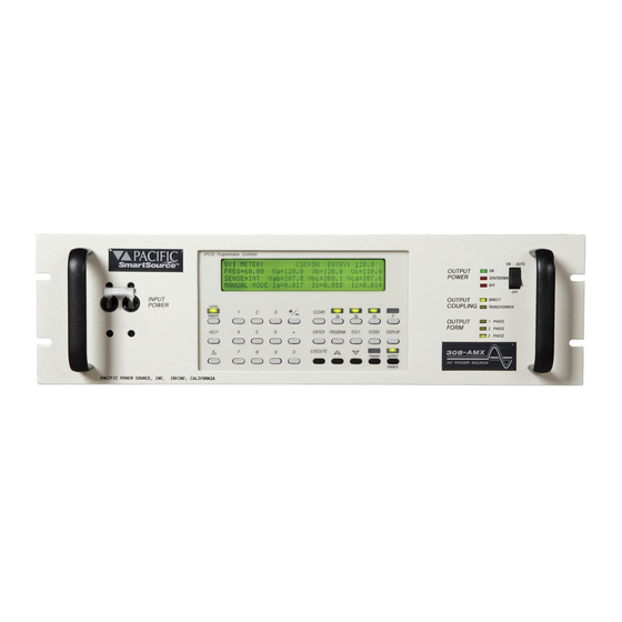
Page 14: Figure 1.3 Amx-Series Power Source - Front View
SECTION 1 GENERAL GENERAL PRODUCT DESCRIPTION (cont.) MODEL 305−AMX w/ UPC−3M Controller MODEL 360−AMX FIGURE 1.3 AMX-SERIES POWER SOURCE - FRONT VIEW... -
Page 15: Specifications
SECTION 2 SPECIFICATIONS SPECIFICATIONS This section states the electrical specifications of the AMX-Series Power Source. specifications listed apply to all models, except as noted. Some specifications are controller dependent. These are noted as such. ELECTRICAL SPECIFICATIONS 2.1.1 INPUT POWER REQUIREMENTS This paragraph lists and defines the input voltage forms that are accepted by the various models within the AMX-Series line of equipment. - Page 16 SECTION 2 SPECIFICATIONS 2.1.1 INPUT POWER REQUIREMENTS (cont.) MODEL 108-AMX INPUT VOLTAGE AND INPUT CURRENT The Model 108-AMX single phase input voltages, required input currents at full rated load and recommended service input currents are stated as below. INPUT VOLTAGE INPUT SERVICE (360-440 Hz optional)
- Page 17 SECTION 2 SPECIFICATIONS 2.1.1 INPUT POWER REQUIREMENTS (cont.) MODEL 125-AMX INPUT VOLTAGE AND INPUT CURRENT The Model 125-AMX three phase input voltages, required input currents at full rated load and recommended service input currents are stated as below. INPUT CURRENT INPUT SERVICE (360-440 Hz optional)
- Page 18 SECTION 2 SPECIFICATIONS 2.1.1 INPUT POWER REQUIREMENTS (cont.) MODEL 160-AMX INPUT VOLTAGE AND INPUT CURRENT The Model 160-AMX three phase input voltages, required input currents at full rated load and recommended service input currents are stated as below. INPUT CURRENT INPUT SERVICE (360-440 Hz optional)
- Page 19 SECTION 2 SPECIFICATIONS 2.1.1 INPUT POWER REQUIREMENTS (cont.) MODEL 308-AMX INPUT VOLTAGE AND INPUT CURRENT The Model 308-AMX single phase input voltages, required input currents at full rated load and recommended service input currents are stated as below. INPUT CURRENT INPUT SERVICE (360-440 Hz optional)
- Page 20 SECTION 2 SPECIFICATIONS 2.1.1 INPUT POWER REQUIREMENTS (cont.) MODEL 320-AMX INPUT VOLTAGE AND INPUT CURRENT The Model 320-AMX three phase input voltages, required input currents at full rated load and recommended service input currents are stated as below. INPUT CURRENT INPUT SERVICE (360-440 Hz optional)
- Page 21 SECTION 2 SPECIFICATIONS 2.1.1 INPUT POWER REQUIREMENTS (cont.) MODEL 360-AMX INPUT VOLTAGE AND INPUT CURRENT The Model 360-AMX three phase input voltages, required input currents at full rated load and recommended service input currents are stated as below. INPUT CURRENT INPUT SERVICE (360-440 Hz optional)
- Page 22 SECTION 2 SPECIFICATIONS 2.1.1 INPUT POWER REQUIREMENTS (cont.) MODEL 3120-AMX INPUT VOLTAGE AND INPUT CURRENT The Model 3120-AMX three phase input voltages, required input currents at full rated load and recommended service input currents are stated as below. INPUT CURRENT INPUT SERVICE (360-440 Hz optional)
-
Page 23: Output Power
273 VAC 2.5:1 341 VAC NOTE: Models 112-AMX, 125-AMX and 312-AMX require special consideration for transformer-coupled operation. Please contact Pacific Power Source. OUTPUT CURRENT FULL-RATED CURRENT The full-rated output current of the AMX-Series Power Source is listed below by model number. -
Page 24: Figure 2.1.2(A) Model 105-Amx Output Rating Curves
SECTION 2 SPECIFICATIONS 2.1.2 OUTPUT POWER (cont.) FIGURE 2.1.2(A) MODEL 105-AMX OUTPUT RATING CURVES... -
Page 25: Figure 2.1.2(B) Model 108-Amx Output Rating Curves
SECTION 2 SPECIFICATIONS 2.1.2 OUTPUT POWER (cont.) FIGURE 2.1.2(B) MODEL 108-AMX OUTPUT RATING CURVES... -
Page 26: Figure 2.1.2(C) Model 112-Amx Output Rating Curves
SECTION 2 SPECIFICATIONS 2.1.2 OUTPUT POWER (cont.) FIGURE 2.1.2(C) MODEL 112-AMX OUTPUT RATING CURVES... -
Page 27: Figure 2.1.2(D) Model 125-Amx Output Rating Curves
SECTION 2 SPECIFICATIONS 2.1.2 OUTPUT POWER (cont.) FIGURE 2.1.2(D) MODEL 125-AMX OUTPUT RATING CURVES... -
Page 28: Figure 2.1.2(E) Model 140-Amx Output Rating Curves
SECTION 2 SPECIFICATIONS 2.1.2 OUTPUT POWER (cont.) FIGURE 2.1.2(E) MODEL 140-AMX OUTPUT RATING CURVES... -
Page 29: Figure 2.1.2(F) Model 160-Amx Output Rating Curves
SECTION 2 SPECIFICATIONS 2.1.2 OUTPUT POWER (cont.) FIGURE 2.1.2(F) MODEL 160-AMX OUTPUT RATING CURVES... -
Page 30: Figure 2.1.2(G) Model 305-Amx Output Rating Curves
SECTION 2 SPECIFICATIONS 2.1.2 OUTPUT POWER (cont.) FIGURE 2.1.2(G) MODEL 305-AMX OUTPUT RATING CURVES... -
Page 31: Figure 2.1.2(H) Model 308-Amx Output Rating Curves
SECTION 2 SPECIFICATIONS 2.1.2 OUTPUT POWER (cont.) FIGURE 2.1.2(H) MODEL 308-AMX OUTPUT RATING CURVES... -
Page 32: Figure 2.1.2(I) Model 312-Amx Output Rating Curves
SECTION 2 SPECIFICATIONS 2.1.2 OUTPUT POWER (cont.) FIGURE 2.1.2(I) MODEL 312-AMX OUTPUT RATING CURVES... -
Page 33: Figure 2.1.2(J) Model 320-Amx Output Rating Curves
SECTION 2 SPECIFICATIONS 2.1.2 OUTPUT POWER (cont.) FIGURE 2.1.2(J) MODEL 320-AMX OUTPUT RATING CURVES... -
Page 34: Figure 2.1.2(K) Model 345-Amx Output Rating Curves
SECTION 2 SPECIFICATIONS 2.1.2 OUTPUT POWER (cont.) FIGURE 2.1.2(K) MODEL 345-AMX OUTPUT RATING CURVES... -
Page 35: Figure 2.1.2(L) Model 360-Amx Output Rating Curves
SECTION 2 SPECIFICATIONS 2.1.2 OUTPUT POWER (cont.) FIGURE 2.1.2(L) MODEL 360-AMX OUTPUT RATING CURVES... -
Page 36: Figure 2.1.2(M) Model 390-Amx Output Rating Curves
SECTION 2 SPECIFICATIONS 2.1.2 OUTPUT POWER (cont.) FIGURE 2.1.2(M) MODEL 390-AMX OUTPUT RATING CURVES... -
Page 37: Figure 2.1.2(N) Model 3120-Amx Output Rating Curves
SECTION 2 SPECIFICATIONS 2.1.2 OUTPUT POWER (cont.) FIGURE 2.1.2(N) MODEL 3120-AMX OUTPUT RATING CURVES... -
Page 38: Output Power Factor
SECTION 2 SPECIFICATIONS 2.1.3 OUTPUT POWER FACTOR The AMX-Series Power Source is designed to operate into any load power factor. For load power factors less than ±0.7, the available output power is rated as shown by the Power Factor Rating chart of Figures 2.1.2(A-N). 2.1.4 OUTPUT FREQUENCY The output frequency range of the AMX-Series Power Source is determined by the controller which is installed in the system. -
Page 39: Output Bandwidth
SECTION 2 SPECIFICATIONS 2.1.8 OUTPUT BANDWIDTH The output bandwidth of the AMX-Series Power Source is listed below. Full Power: 500 Hz (±0.10 db [± 1%]) 5,000 Hz (±0.25 db [± 3%]) Small Signal: 40,000 Hz (±3 db [±30%]) (rated at 10% of full-scale output voltage) 2.1.9 LOAD TRANSIENT RESPONSE Output load transient response for a 0-100% load induced step transient is approximately 5 μsec. -
Page 40: Mechanical Specifications
SECTION 2 SPECIFICATIONS MECHANICAL SPECIFICATIONS This paragraph describes the mechanical characteristics of the AMX-Series Power Sources. 2.2.1 DIMENSIONS POWER SOURCE: Dimensions of the AMX-Series Power Sources are listed below. MODEL 105-AMX Height: 5.25" [134 mm] Width: 19.00" [483 mm] (front panel); 16.75"... - Page 41 SECTION 2 SPECIFICATIONS 2.2.1 DIMENSIONS (cont.) POWER SOURCE: MODEL 140-AMX Height: 14.00" [356 mm] Width: 19.00" [483 mm] (front panel); 17.00" [432 mm] (chassis) Depth: 23.50" [597 mm] Weight: 185 lbs. [84 kg] Refer to Figure 2.2.3 for the outline drawing of the Model 140-AMX. MODEL 160-AMX Height: 14.00"...
- Page 42 SECTION 2 SPECIFICATIONS 2.2.1 DIMENSIONS (cont.) POWER SOURCE: MODEL 320-AMX Height: 8.75" [222 mm] Width: 19.00" [483 mm] (front panel); 16.75" [426 mm] (chassis) Depth: 23.12" [587 mm] (measured from back side of front panel, excludes terminal blocks) Weight: 150 lbs. [68 kg] Refer to Figure 2.2.2 for the outline drawing of the Model 320-AMX.
-
Page 43: Input Power Connection
SECTION 2 SPECIFICATIONS 2.2.1 DIMENSIONS (cont.) POWER SOURCE: MODEL 3120-AMX Height: 28.00" [712 mm] (14.00" [356 mm] x 2ea) Width: 19.00" [483 mm] (front panel); 17.00" [432 mm] (chassis) Depth: 23.50" [597 mm] Weight: 390 lbs [176 kg] (180 lbs. [82 kg] x 2ea) Refer to Figure 2.2.4 for the outline drawing of the Model 3120-AMX. -
Page 44: Figure 2.2.1 Outline Drawing, Models 105/108/112/305/308/312-Amx
SECTION 2 SPECIFICATIONS 2.2.2 INPUT POWER CONNECTION (cont.) FIGURE 2.2.1 OUTLINE DRAWING, MODELS 105/108/112/305/308/312-AMX... -
Page 45: Figure 2.2.2 Outline Drawing, Model 320-Amx
SECTION 2 SPECIFICATIONS 2.2.2 INPUT POWER CONNECTION (cont.) FIGURE 2.2.2 OUTLINE DRAWING, MODEL 320-AMX... -
Page 46: Figure 2.2.3 Outline Drawing, Models 125/140/345/360-Amx
SECTION 2 SPECIFICATIONS 2.2.2 INPUT POWER CONNECTION (cont.) FIGURE 2.2.3 OUTLINE DRAWING, MODELS 125/140/160/345/360-AMX... -
Page 47: Figure 2.2.4 Outline Drawing, Models 390 & 3120-Amx And Magnetics Module
SECTION 2 SPECIFICATIONS 2.2.2 INPUT POWER CONNECTION (cont.) FIGURE 2.2.4 OUTLINE DRAWING, MODELS 390 & 3120-AMX AND MAGNETICS MODULE... -
Page 48: Output Power Connection
The chassis of the AMX-Series Power Source is designed to accept slide rails. These can be provided as a cost option. For more information, contact your local sales representative or the Pacific Power Source Sales Office. ENVIRONMENTAL SPECIFICATIONS This paragraph lists the environmental requirements of the AMX-Series Power Source. -
Page 49: Installation
SECTION 3 INSTALLATION INSTALLATION This section describes the installation of the AMX-Series AC Power Source. NOTE: ETL LABELED UNITS ONLY For models 105,108,112,305,308,312 and 320-AMX, an input power cord plug is provided to meet ETL safety standard requirement. For models 125,140, 345,360,390 and 3120-AMX, the input terminal block cover is provided to meet ETL safety standard requirement. - Page 50 When the power source is placed in a 19 inch rack, it must be supported by either chassis slides or full depth angle brackets. The front panel alone will not support the weight of the power source. Chassis slides are available from Pacific Power Source as a cost option. Call factory service for details.
-
Page 51: Output Voltage Range Configuration
SECTION 3 INSTALLATION OUTPUT VOLTAGE RANGE CONFIGURATION The AMX-Series Power Source can be configured for several different Output Voltage Ranges. The standard output configurations are: Transformer Voltage Range Model Ratio Standard on most models. 0-135 VAC Direct 112-AMX,125-AMX and 312-AMX Coupled 0-150 VAC Models 105-AMXT, 108-AMXT, 140-AMXT,... -
Page 52: Output Voltage Range Configuration, Models 105-Amxt And 108-Amxt
SECTION 3 INSTALLATION 3.2.1 OUTPUT VOLTAGE RANGE CONFIGURATION, MODELS 105-AMXT and 108-AMXT The Output Voltage Range for the Models 105-AMXT and 108-AMXT Power Sources can be configured for either 0-135 VAC , 0-204 VAC , 0-273 VAC , or 0-341 VAC . -
Page 53: Figure 3.2.1 Models 105 & 108-Amx Output Voltage Configuration
SECTION 3 INSTALLATION 3.2.1 OUTPUT VOLTAGE RANGE CONFIGURATION, MODELS 105-AMXT and 108-AMXT (cont.) FIGURE 3.2.1 MODELS 105 & 108-AMXT OUTPUT VOLTAGE CONFIGURATION... -
Page 54: Output Voltage Range Configuration, Model 112-Amx
SECTION 3 INSTALLATION 3.2.2 OUTPUT VOLTAGE RANGE CONFIGURATION, MODEL 112-AMX The Output Voltage Range for the Model 112-AMX Power Source can be configured for either 0-110 VAC , 0-125 VAC , 0-135 VAC , or 0-150 VAC . All ranges are direct-coupled outputs and are provided to maximize output current for a given output voltage. -
Page 55: Figure 3.2.41 Models 305 & 308-Amx Output Voltage Configuration
SECTION 3 INSTALLATION 3.2.4 OUTPUT VOLTAGE RANGE CONFIGURATION, MODELS 305-AMXT and 308-AMXT (cont.) FIGURE 3.2.41 MODELS 305 & 308-AMXT OUTPUT VOLTAGE CONFIGURATION... -
Page 56: Output Voltage Range Configuration, Model 312-Amx
SECTION 3 INSTALLATION 3.2.5 OUTPUT VOLTAGE RANGE CONFIGURATION, MODEL 312-AMX The Output Voltage Range for the Model 312-AMX Power Source can be configured for either 0-110 VAC , 0-125 VAC , 0-135 VAC , or 0-150 VAC . All ranges are direct-coupled outputs and are provided to maximize output current for a given output voltage. -
Page 57: Output Voltage Range Configuration, Models 140-Amxt, 160-Amxt
The Amps to Volts Ratio Setting of the UPC is always set to 30 for the Models 390-AMX and 3120-AMX. (Refer to the UPC-Series Operation Manual for details.) While the above procedure can be performed in the field, Pacific Power Source recommends that the system be returned to the factory when transformer-coupled outputs are to be added... -
Page 58: Figure 3.2.71 Models 140/160/320/345/360/390/3120-Amx Output Voltage Configuration
SECTION 3 INSTALLATION 3.2.6 OUTPUT VOLTAGE RANGE CONFIGURATION, MODELS 140-AMXT, 160-AMXT, 320-AMXT, 345-AMXT, 360-AMXT, 390-AMXT and 3120-AMXT (cont.) FIGURE 3.2.71 MODELS 140/160/320/345/360/390/3120-AMXT OUTPUT VOLTAGE CONFIGURATION... -
Page 59: Input Power Connection
SECTION 3 INSTALLATION INPUT POWER CONNECTION Input voltage form and requirements of the input wiring for the AMX-Series Power Source varies by model. Each is discussed in a separate paragraph. Please refer to the appropriate paragraph for the model being configured. 3.3.1 INPUT VOLTAGE CONFIGURATION, MODELS 105-AMX, 108-AMX, 305-AMX and 308-AMX WARNING... -
Page 60: Figure 3.3.1 Models 105/108/305/308-Amx Input Voltage Configuration
SECTION 3 INSTALLATION 3.3.1 INPUT VOLTAGE CONFIGURATION, MODELS 105-AMX, 108-AMX, 305-AMX and 308-AMX (cont.) FIGURE 3.3.1 MODELS 105/108/305/308-AMX INPUT VOLTAGE CONFIGURATION... -
Page 61: Input Voltage Configuration, Models 112-Amx And 312-Amx
SECTION 3 INSTALLATION 3.3.2 INPUT VOLTAGE CONFIGURATION, MODELS 112-AMX and 312-AMX WARNING DISCONNECT THIS UNIT FROM THE INPUT SERVICE BEFORE REMOVING TOP COVER. HIGH VOLTAGE HAZARD PRESENT INSIDE UNIT WHEN TOP COVER IS REMOVED AND STILL CONNECTED TO INPUT SERVICE. The 112 and 312-AMX Power Sources have been designed to accept most standard single phase input voltage forms. -
Page 62: Figure 3.3.2 Models 112 & 312-Amx Input Voltage Configuration
SECTION 3 INSTALLATION 3.3.2 INPUT VOLTAGE CONFIGURATION, MODELS 112-AMX and 312-AMX (cont.) FIGURE 3.3.2 MODELS 112 & 312-AMX INPUT VOLTAGE CONFIGURATION... -
Page 63: Input Voltage Configuration, Model 320-Amx
SECTION 3 INSTALLATION 3.3.3 INPUT VOLTAGE CONFIGURATION, MODEL 320-AMX WARNING DISCONNECT THIS UNIT FROM THE INPUT SERVICE BEFORE REMOVING TOP COVER. HIGH VOLTAGE HAZARD PRESENT INSIDE UNIT WHEN TOP COVER IS REMOVED AND STILL CONNECTED TO INPUT SERVICE. The 320-AMX Power Source has been designed to accept most standard three phase input voltage forms. -
Page 64: Figure 3.3.3 Model 320-Amx Input Voltage Configuration
SECTION 3 INSTALLATION 3.3.3 INPUT VOLTAGE CONFIGURATION, MODEL 320-AMX (cont.) FIGURE 3.3.3 MODEL 320-AMX INPUT VOLTAGE CONFIGURATION... -
Page 65: Input Voltage Configuration, Model 125-Amx
SECTION 3 INSTALLATION 3.3.4 INPUT VOLTAGE CONFIGURATION, MODEL 125-AMX WARNING DISCONNECT THIS UNIT FROM THE INPUT SERVICE BEFORE REMOVING TOP COVER. HIGH VOLTAGE HAZARD PRESENT INSIDE UNIT WHEN TOP COVER IS REMOVED AND STILL CONNECTED TO INPUT SERVICE. The 125-AMX Power Source has been designed to accept most standard three phase input voltage forms. -
Page 66: Figure 3.3.4 Model 125-Amx Input Voltage Configuration
SECTION 3 INSTALLATION 3.3.4 INPUT VOLTAGE CONFIGURATION, MODEL 125-AMX (cont.) FIGURE 3.3.4 MODEL 125-AMX INPUT VOLTAGE CONFIGURATION... -
Page 67: Input Voltage Configuration, Models 140-Amx, 160-Amx, 345-Amx, 360-Amx, 390-Amx And 3120-Amx
SECTION 3 INSTALLATION 3.3.5 INPUT VOLTAGE CONFIGURATION, MODELS 140-AMX, 160-AMX, 345-AMX, 360-AMX, 390-AMX and 3120-AMX WARNING DISCONNECT THIS UNIT FROM THE INPUT SERVICE BEFORE REMOVING TOP COVER. HIGH VOLTAGE HAZARD PRESENT INSIDE UNIT WHEN TOP COVER IS REMOVED AND STILL CONNECTED TO INPUT SERVICE. The 140-AMX, 160-AMX, 345-AMX, 360-AMX, 390-AMX and 3120-AMX Power Sources have been designed to accept most standard three phase input voltage forms. -
Page 68: Figure 3.3.5 Models 140/345/360/390/3120-Amx Input Voltage Configuration
SECTION 3 INSTALLATION 3.3.5 INPUT VOLTAGE CONFIGURATION, MODELS 140-AMX, 160-AMX, 345-AMX, 360-AMX, 390-AMX and 3120-AMX (cont.) FIGURE 3.3.5 MODELS 140/160/345/360/390/3120-AMX INPUT VOLTAGE CONFIGURATION... -
Page 69: Input Power Wiring Requirements
SECTION 3 INSTALLATION 3.3.6 INPUT POWER WIRING REQUIREMENTS WARNING LETHAL VOLTAGE PRESENT AT INPUT TERMINALS OF THIS MACHINE. ALWAYS CONNECT "CHS or GND" TERMINAL TO EARTH POTENTIAL. FAILURE TO DO SO WILL CREATE A SHOCK HAZARD. The Models 105-AMX, 108-AMX, 112-AMX, 305-AMX, 308-AMX, 312-AMX and 320-AMX are supplied with an input power cord. -
Page 70: Figure 3.3.6 Models 125/140/345/360/390/3120-Amx Input Wiring Diagram
SECTION 3 INSTALLATION 3.3.6 INPUT POWER WIRING REQUIREMENTS (cont.) FIGURE 3.3.6 MODELS 140/160/345/360/390/3120-AMX INPUT WIRING DIAGRAM... -
Page 71: Output Power Connection
This allows the user to re-establish a local ground for the output. The output must be refer- enced to chassis somewhere, preferably neutral. Unless demanded otherwise by a par- ticular application, Pacific Power Source recommends that a jumper be installed across the "N" ("L2" for Model 125-AMX) and "CHS" terminals of the Output Terminal block. -
Page 72: Figure 3.4.1.1 Models 125/140/345/360/390/3210-Amx Single Phase Output Connection
SECTION 3 INSTALLATION 3.4.1 SINGLE PHASE OUTPUT (cont.) FIGURE 3.4.1.1 MODELS 105/108/112/305/308/312/320-AMX SINGLE PHASE OUTPUT CONNECTION... -
Page 73: Figure 3.4.1.2 Models 105/108/112/305/308/312/320-Amx Single Phase Output Connection
SECTION 3 INSTALLATION 3.4.1 SINGLE PHASE OUTPUT (cont.) FIGURE 3.4.1.2 MODELS 125/140/160/345/360/390/3120-AMX SINGLE PHASE OUTPUT CONNECTION... -
Page 74: Split Phase Output
Neutral) must be referenced to chassis somewhere. Unless demanded otherwise by a par- ticular application, Pacific Power Source recommends that a jumper be installed across the "N" ("L2" terminal for Model 125-AMX) and "CHS" terminals of the Output Terminal block. -
Page 75: Figure 3.4.2.1 Models 125/140/345/360/390/3210-Amx Split Phase Output Connection
SECTION 3 INSTALLATION 3.4.2 SPLIT PHASE OUTPUT (cont.) FIGURE 3.4.2.1 MODELS 105/108/112/305/308/312/320-AMX SPLIT PHASE OUTPUT CONNECTION... -
Page 76: Figure 3.4.2.2 Models 105/108/112/305/308/312/320-Amx Split Phase Output Connection
SECTION 3 INSTALLATION 3.4.2 SPLIT PHASE OUTPUT (cont.) FIGURE 3.4.2.2 MODELS 125/140/160/345/360/390/3120-AMX SPLIT PHASE OUTPUT CONNECTION... -
Page 77: Three Phase Output
This allows the user to re-establish a local ground for the output. The output (preferably Neutral) must be referenced to chassis somewhere. Unless demanded otherwise by a par- ticular application, Pacific Power Source recommends that a jumper be installed across the "N" and "CHS" terminals of the Output Terminal block. -
Page 78: Figure 3.4.3.1 Models 345/360/390/3210-Amx Three Phase Output Connection
SECTION 3 INSTALLATION 3.4.3 THREE PHASE OUTPUT (cont.) FIGURE 3.4.3.1 MODELS 305/308/312/320-AMX THREE PHASE OUTPUT CONNECTION... -
Page 79: Figure 3.4.3.2 Models 305/308/312-Amx Three Phase Output Connection
SECTION 3 INSTALLATION 3.4.3 THREE PHASE OUTPUT (cont.) FIGURE 3.4.3.2 MODELS 345/360/390/3120-AMX THREE PHASE OUTPUT CONNECTION... -
Page 80: Transformer Outputs - Special Considerations
SECTION 3 INSTALLATION 3.4.4 TRANSFORMER OUTPUTS - SPECIAL CONSIDERATIONS OUTPUT GROUNDING The output of the AMX-Series Power Source is electrically isolated from the input power and earth ground. This allows the user to establish a local ground for the output of the Power Source. -
Page 81: Master - Slave Paralleling Interconnections (M5283)
SECTION 3 INSTALLATION 3.4.5 MASTER - SLAVE PARALLELING INTERCONNECTIONS (M5283) The paralleling option, M5283, for models 140, 160, 345, and 360AMX provides the ability to create a multi-unit AC Power Source system that parallels up to five power sources for increased power. Paralleled units must all be the same model, and each system must contain at least one designated master unit, however, any combination of master/slave selectable or dedicated slave units may connected to the designated master. - Page 82 SECTION 3 INSTALLATION 3.4.5 MASTER - SLAVE PARALLELING INTERCONNECTIONS (M5283) (cont.) ROUTINE POWER-UP, PARALLELED SYSTEM The following procedure is recommended to turn on paralleled systems after it has been verified that the installation is correct. WARNING LETHAL VOLTAGES ARE PRESENT AT THE OUTPUT TERMINALS OF THIS MACHINE! Set the OUTPUT POWER switch of the Master Chassis (that which has the controller installed) to the OFF position.
- Page 83 SECTION 3 INSTALLATION 3.4.5 MASTER - SLAVE PARALLELING INTERCONNECTIONS (M5283) (cont.) SYSTEM TURN-OFF, PARALLELED SYSTEM This paragraph describes the procedure used to turn off the paralleled systems. The paralleled systems are turned off by: Setting the OUTPUT POWER Switch of the Master chassis (which has the controller installed) to the OFF position.
-
Page 84: Figure 3.4.5.1 Models 140,160, 345 & 360-Amx M5283 Two Chassis
SECTION 3 INSTALLATION 3.4.5 MASTER - SLAVE PARALLELING INTERCONNECTIONS (M5283) (cont.) FIGURE 3.4.5.1 MODELS 140,160, 345 & 360-AMX M5283 TWO CHASSIS INTERCONNECTION... -
Page 85: Remote Interface
SECTION 3 INSTALLATION REMOTE INTERFACE The programmable controller (UPC-Series Controller) is supplied with one of two remote interfaces. These are the GPIB (General Purpose Interface Bus) or RS-232 Interface. Connection information relative to these interfaces is described in detail in the UPC-Series Operation manual. -
Page 86: External Sense Connection
SECTION 3 INSTALLATION EXTERNAL SENSE CONNECTION This paragraph describes connection of external sense leads to the AMX-Series Power Source. External Sense wire size and methods are discussed. The AMX-Series Power Source contains External Sense Circuits. These circuits measure output voltage at an external sense point. Since this feature can be completely disabled, the wiring detailed in this paragraph is optional. -
Page 87: Figure 3.7.1 Models 125/140/345/360/390/3120-Amx External Sense Connection
SECTION 3 INSTALLATION EXTERNAL SENSE CONNECTION (cont.) FIGURE 3.7.1 MODELS 105/108/305/308/112/312/320-AMX EXTERNAL SENSE CONNECTION... -
Page 88: Figure 3.7.2 Models 105/108/305/308/112/312/320-Amx External Sense Connection
SECTION 3 INSTALLATION EXTERNAL SENSE CONNECTION (cont.) FIGURE 3.7.2 MODELS 125/140/160/345/360/390/3120-AMX EXTERNAL SENSE CONNECTION... -
Page 89: Operation
SECTION 4 OPERATION OPERATION This section describes the operation of an AMX-Series AC Power Source. The procedure described in the following paragraphs is a general procedure common to all systems (except as noted). This procedure does not detail operation of a specific controller. Refer to the appropriate controller manual for detailed information regarding the installed controller. -
Page 90: Figure 4.1 Front Panel Controls
SECTION 4 OPERATION FRONT PANEL CONTROLS (cont.) OUTPUT POWER SWITCH and INDICATORS INPUT POWER SWITCH OUTPUT COUPLING INDICATORS OUTPUT FORM INIDCATORS MODEL 320−AMX w/ UPC−32 Controller FIGURE 4.1 FRONT PANEL CONTROLS... -
Page 91: Initial Power-Up
SECTION 4 OPERATION INITIAL POWER-UP To turn on the AMX-Series Power Source for the first time, the steps below are the recommended order of operation. WARNING LETHAL VOLTAGES ARE PRESENT AT THE OUTPUT TERMINALS OF THIS MACHINE! For new installations, check input connections (including proper input voltage). Do not connect the load at this time. -
Page 92: Routine Power-Up
SECTION 4 OPERATION ROUTINE POWER-UP The following procedure is recommended to turn-on paralleled systems after it has been verified that the installation is correct. WARNING LETHAL VOLTAGES ARE PRESENT AT THE OUTPUT TERMINALS OF THIS MACHINE! Set the OUTPUT POWER switch to the OFF position. Switch the INPUT POWER switch to the ON position. -
Page 93: Routine Power-Up, Models 390 And 3120-Amx
SECTION 4 OPERATION 4.3.1 ROUTINE POWER-UP, MODELS 390 and 3120-AMX This paragraph describes the procedure used to turn on the Models 390 and 3120-AMX Power Sources after if has been verified that the installation is correct. The steps below are the recommended order of operation. -
Page 94: System Turn-Off
SECTION 4 OPERATION SYSTEM TURN-OFF This paragraph describes the procedure used to turn off the AMX-Series Power Source. The AMX-Series Power Source is turned off by: Setting the OUTPUT POWER Switch to the OFF position. Opening the INPUT POWER circuit breaker 4.4.1 SYSTEM TURN-OFF, MODELS 390 and 3120-AMX This paragraph describes the procedure used to turn off the 390 and 3120-AMX Power Sources. -
Page 95: System Shutdown
SECTION 4 OPERATION SYSTEM SHUTDOWN This paragraph describes the conditions which will cause system shutdown and the procedure used to reset the AMX-Series Power Source. 4.5.1 SHUTDOWN CONDITIONS The Output Contactor of the AMX-Series Power Source will be opened automatically when: Either the Input Power Transformer or one of the power amplifier assemblies has reached an Over-temperature condition. -
Page 96: Output Voltage Forms
SECTION 4 OPERATION OUTPUT VOLTAGE FORMS The AMX-Series Power Source can be configured for various output voltage forms, depending on the power source model. A recommended strategy for selecting the optimum output voltage form is based on two basic philosophies. The first is to use a direct-coupled output form whenever possible. -
Page 97: Figure 4.6.1 Amx-Series System Architecture
SECTION 4 OPERATION 4.6.1 SYSTEM ARCHITECTURE (cont.) FIGURE 4.6.1 AMX-SERIES SYSTEM ARCHITECTURE... -
Page 98: Maintenance
SECTION 5 MAINTENANCE MAINTENANCE This section describes the maintenance of the AMX-Series AC Power Source. MAINTENANCE INTERVAL Maintenance of the Models 105-AMX, 108-AMX, 112-AMX, 305-AMX, 308-AMX, and 312-AMX Power Sources is required once every six months and consists of performing regular calibration. -
Page 99: Calibration
SECTION 6 CALIBRATION CALIBRATION This section describes calibration of the AMX-Series AC Power Source. CALIBRATION INTERVAL Each AMX-Series Power Source requires calibration once every six months or after service has been performed to the system. TEST EQUIPMENT REQUIREMENTS The test equipment listed below is required for calibration of the AMX-Series Power Source. Digital Voltmeter: 4½... -
Page 100: Calibration Procedure
SECTION 6 CALIBRATION CALIBRATION PROCEDURE This calibration procedure verifies that system gains are set properly and that the system per- formance, relative to output power capability, is intact. Gains in various signal paths within the controller are adjusted by the procedure of Paragraph 6.3.1. Output power capability of the power source is tested by the procedure of Paragraph 6.3.2. -
Page 101: Power Source Load Test
SECTION 6 CALIBRATION 6.3.2 POWER SOURCE LOAD TEST Verify that the power source is able to deliver rated load, and that the output metering function of the controller is also checked. The test proceeds in the manner below. Set the power source for 3φ Output (2φ for models 105, 108, 112, 125, 140 and 160-AMX), Direct-coupled, CSC Enabled. -
Page 102: Service
Part numbers for various components are listed separately for each Model. When questions regarding operation arise or service is required, call the factory for instructions. Pacific Power Source maintains a staff of highly trained technicians who are ready to assist. -
Page 103: Sub-Assembly And Chassis Component Part Numbers
SECTION 7 SERVICE SUB-ASSEMBLY AND CHASSIS COMPONENT PART NUMBERS The factory part numbers given in the following sections are provided to aid the user in obtaining spare or repair sub-assemblies and components where the factory has given permission, in advance, for the user to perform field repairs on the AMX-Series Power Source 7.3.1 FACTORY PART NUMBERS, MODEL 105-AMX (PART NUMBER 143141) SUB-ASSEMBLY FACTORY PART No. -
Page 104: Factory Part Numbers, Model 112-Amx
SECTION 7 SERVICE 7.3.3 FACTORY PART NUMBERS, MODEL 112-AMX (PART NUMBER 143146) SUB-ASSEMBLY FACTORY PART No. Power Amplifier PCB: 139070 LED Display PCB: 139071 Output Filter PCB: 139073 Low Voltage Power Supply/Fan Speed Cont. PCB: 139074 Power Factor Correction PCB: 139075 Control/Logic PCB: 139078... -
Page 105: Factory Part Numbers, Model 140-Amx
SECTION 7 SERVICE 7.3.5 FACTORY PART NUMBERS, MODEL 140-AMX (PART NUMBER 143140) SUB-ASSEMBLY FACTORY PART No. Control/Metering PCB: 134170 Input Filter PCB: 134175 Input Filter PCB: 134177 External Sense Filter PCB: 134178 Output Filter PCB: 134179 Power Amplifier PCB: 134477 Voltage Amplifier PCB: 134671 LED Display PCB:... -
Page 106: Factory Part Numbers, Model 305-Amx
SECTION 7 SERVICE 7.3.7 FACTORY PART NUMBERS, MODEL 305-AMX (PART NUMBER 143143) SUB-ASSEMBLY FACTORY PART No. LED Display PCB: 139071 Low Voltage Power Supply/Fan Speed Cont. PCB: 139074 Output Filter PCB: 139073 Power Amplifier PCB: 139077 Control/Logic PCB: 139078 Input Filter PCB: 140079 LVPS Fuse PCB: 140373... -
Page 107: Factory Part Numbers, Model 312-Amx
SECTION 7 SERVICE 7.3.9 FACTORY PART NUMBERS, MODEL 312-AMX (PART NUMBER 143147) SUB-ASSEMBLY FACTORY PART No. LED Display PCB: 139071 Output Filter PCB: 139073 Low Voltage Power Supply/Fan Speed Cont. PCB: 139074 Power Factor Correction PCB: 139075 Power Amplifier PCB: 139077 Control/Logic PCB: 139078... -
Page 108: Factory Part Numbers, Model 345-Amx
SECTION 7 SERVICE 7.3.11 FACTORY PART NUMBERS, MODEL 345-AMX (PART NUMBER 143126) SUB-ASSEMBLY FACTORY PART No. Control/Metering PCB: 134170 Input Filter PCB: 134175 Voltage Amplifier PCB: 134176 Input Filter PCB: 134177 External Sense Filter PCB: 134178 Output Filter PCB: 134179 LED Display PCB: 139071 Power Amplifier PCB:... -
Page 109: Factory Part Numbers, Model 360-Amx
SECTION 7 SERVICE 7.3.12 FACTORY PART NUMBERS, MODEL 360-AMX (PART NUMBER 143127) SUB-ASSEMBLY FACTORY PART No. Control/Metering PCB: 134170 Input Filter PCB: 134175 Voltage Amplifier PCB: 134176 Input Filter PCB: 134177 External Sense Filter PCB: 134178 Output Filter PCB: 134179 Power Amplifier PCB: 134477 LED Display PCB:... -
Page 110: Factory Part Numbers, Model 390-Amx
SECTION 7 SERVICE 7.3.13 FACTORY PART NUMBERS, MODEL 390-AMX (PART NUMBER 143128) SUB-ASSEMBLY FACTORY PART No. Control/Metering PCB: 134170 Input Filter PCB: 134175 Voltage Amplifier PCB: 134176 Input Filter PCB: 134177 External Sense Filter PCB: 134178 Output Filter PCB: 134179 LED Display PCB: 139071 Power Amplifier PCB:... -
Page 111: Factory Part Numbers, Model 3120-Amx
SECTION 7 SERVICE 7.3.14 FACTORY PART NUMBERS, MODEL 3120-AMX (PART NUMBER 143129) SUB-ASSEMBLY FACTORY PART No. Control/Metering PCB: 134170 Input Filter PCB: 134175 Voltage Amplifier PCB: 134176 Input Filter PCB: 134177 External Sense Filter PCB: 134178 Output Filter PCB: 134179 Power Amplifier PCB: 134477 LED Display PCB:... -
Page 112: Index
SECTION 8 INDEX 2 L 2 Phase See Split Phase, See Split Phase Low Frequency ........72 A M Airflow ..........40, 42 Magnetics Module ......... 35 AMPS TO VOLTS RATIO manual controller ........4 105/108-AMX ........44 O 312/320-AMX ........48 AUX I/O .......... -
Page 113: Modifications And Change Notices
SECTION 9 MODIFICATIONS AND CHANGE NOTICES MODIFICATIONS AND CHANGE NOTICES In cases where customer specified modifications have been installed in the equipment, the modifications will be described on the following pages. If present, be sure to notice any special instructions relative to operation and calibration of the system. Product change notices or manual errata will also be placed in this section.
Need help?
Do you have a question about the AMX Series and is the answer not in the manual?
Questions and answers