Table of Contents
Advertisement
Quick Links
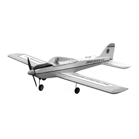
SUPER SPORTS 40S
0.40-0.55 cu. in. displacement 2-stroke
0.52-0.56 cu. in. displacement 4-stroke
Requires: 4-channel radio w/ 4 standard servos
Wing Span
Wing Area
Flying Weight
Fuselage Length
Warning ! This model is not a toy.
It is designed for maximum performance. Please seek advice if one is not familiar with this kind
of electric powered precision model. Operating this model without prior preparation may cause
injuries. Remember, safety is the most important thing. Always keep this instruction manual at
hand for quick reference.
The World Models
Manufacturing Co., Ltd.
www.theworldmodels.com
A049SPO31241512
Specifications
* Specifications are subject to change without notice.*
INSTRUCTION MANUAL
56.5 in / 1440 mm
574 sq in / 37.0 sq dm
5.5 lbs / 2500 g
48.0 in / 1220 mm
ALMOST-READY-TO-FLY(ARF)SERIES
FACTORY PRE-FABRICATED
MADE IN CHINA
Advertisement
Table of Contents

Related Manuals for THE WORLD MODELS SUPER SPORTS 40S


Summary of Contents for THE WORLD MODELS SUPER SPORTS 40S
- Page 1 INSTRUCTION MANUAL SUPER SPORTS 40S 0.40-0.55 cu. in. displacement 2-stroke 0.52-0.56 cu. in. displacement 4-stroke Requires: 4-channel radio w/ 4 standard servos Specifications Wing Span 56.5 in / 1440 mm Wing Area 574 sq in / 37.0 sq dm Flying Weight 5.5 lbs / 2500 g...
-
Page 2: Parts List
SUPER SPORTS 40S INDEX BEFORE YOU BEGIN PARTS LIST ASSEMBLY P.3-P.10 SAFETY PRECAUTIONS P.11 BEFORE YOU BEGIN Read through the manual before you begin, so you will have an overall idea of what to do. Check all parts. If you find any defective or missing parts contact your local dealer. Please DRY FIT and check for defects for all parts that will require CA or Epoxy for final assembly. - Page 3 Parts List 1. MAIN WING -- 1 pair SCREW PWA2.6x12mm -- 4 pcs SILICON GROMMET d1.5x6.5mm (For Cowling) -- 4 pcs 2. RING Ø2.3mm (For Aileron) -- 2 pcs COWLING -- 1 pc. 3. WING JOINER 6x16x84mm -- 1 pc. TRANSPARENT 3D TEMPLATE -- 1 pc.
- Page 4 Main Wing Pre-glued Pre-glued Bottom View Main Wing Cut out to fit in the aileron servo. Main Wing Warning! Please dry fit wing joiner into left and right wing to make sure they fit with the proper dihedral angle, mark the wing joiner if necessary.
- Page 5 Main Wing Cut out to fit in the aileron servo. Plywood 3x45x90mm Aileron Servo 1.5mm 1.5mm Aileron Servo Straper Fuel Tube Ø6x5mm TWM PL8210010 CLEVIS WRENCH Clevis Ring A049SPO31241512...
- Page 6 Main Landing Gear PA3x12mm Screw PA3x12mm Plate Bottom View Main Landing Gear 3mm Set Screw 3.1mm Collar 3.1mm Collar 3mm Set Screw Bottom View Stabilizer & Elevator PM3x25mm PM3x22mm Washer PM3x22mm Screw Washer d3xD12mm d3xD12mm PM3x25mm Screw d3xD12mm Washer Pre-glued Bottom View A049SPO31241512...
-
Page 7: Fuel Tank
Vertical Fin & Rudder A’ A =A’ Pre-glued Fuel Tank Cable Tie Battery Cover (For Fuel Tank) 1.5x5x400mm Fuel Tank 320cc Double-sided Tape 40x100mm Bottom View Cable Tie (For Fuel Tank) 1.5x5x400mm Completed Double-sided Tape 40x100mm A049SPO31241512... -
Page 8: Front Wheel
Engine Mount M3x25mm Socket Head Screw Engine Mount PL5111030 d3xD7 Washer Washer d3xD7mm M3x25mm Socket Head Screw Front Wheel 3mm Set Screw 3mm Set Screw 4.1mm Collar Completed Front View If the engine throttle control is on the opposite side, install the throttle pushwire accordingly. Engine Install the throttle servo with the drive pinion on the same side of throttle pushwire. -
Page 9: Rudder Pushrod
Rudder Pushrod Ø1mm pilot holes for World Models tri-horn are pre-drilled. Please look for pin-hole marks at under side of control surfaces. PB2x12mm Screw Rudder Tri-Horn Fuel Tube Pushrod Ø1.8x745mm 20mm Tri-Horn 166mm M3x22mm PB2x12mm TWM PL8210010 CLEVIS WRENCH Ø1mm pilot holes for World Models tri-horn are pre-drilled. Elevator Pushrod Please look for pin-hole marks at under side of control surfaces. -
Page 10: Radio Equipment
Radio Equipment Install and arrange the servo as shown in the diagram. Front Wheel Pushrod Throttle Balsa 6x6x95mm Ø1.6 x 330mm Servo Battery Receiver Rudder Servo Fuel Tank Fuel Tube Straper Ø6x5mm 320cc Elevator Servo Front Sponge Throttle Pushwire Plywood 3x82X95mm Ø1.2 x 355mm Charge Receptacles KP0041300... - Page 11 Adjust the wing and fuselage configuration Wing Setting as shown in the diagrams. A = A ' B = B ' C = C' Adjust the control throws as shown in the diagram. Control Throws These throws are good for general flying. You can adjust according to your personal preference.
- Page 12 # Pre-flight adjustment must be done before flying, it is very dangerous to fly a badly pre -adjusted aircraft. SUPER SPORTS 40S is specially designed to be powered by 2C 0.40 - 0.55 or 4C 0.52-0.56 engine, using a more powerful engine does not mean better performance. In fact, over powered engine may cause severe damage and injuries.
- Page 13 Usage of the transparent 3D template This transparent 3D template is used for position guidance of the actual cutting of the pre-painted cowling. Simply cut the transparent 3D template to fit your engine and exhaust pipe, then slide onto the actual cowling and use as template to mark the openings required for final cutting.
- Page 14 LINKAGE CONNECTOR HW7111050 & HW7111060 Drill 2mm hole at servo horn. Insert linkage connector into servo horn. Make sure shoulder of screw is cleared from servo horn. Add washer to reduce play if necessary. Shoulder Tighten up the round nut against the shoulder.
- Page 15 Fuel Filter 180mm Extension Package Package Code No. Size Code No. Size Package Code No. Size Package Code No. Size Large Clevis Small Clevis Special tool for clevis installation. Suitable for standard and small Package Code No. Size (EP)clevis. KP0041300 Code No SV4031 Package Code No.
- Page 16 The World Models Manufacturing Co., Ltd. www.theworldmodels.com A049SPO31241512...
Need help?
Do you have a question about the SUPER SPORTS 40S and is the answer not in the manual?
Questions and answers