Table of Contents
Advertisement
Quick Links
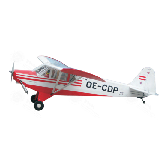
1/4 SUPER CUB
1/4 SUPER CUB
Requires:2 stroke 0
-
5-channel radio w 6 standard servos
Wing Span
Wing Area
Flying Weight
Fuselage Length
* Specifications are subject to change without notice.*
Warning ! This model is not a toy.
It is designed for maximum performance. Please seek advice if one is not familiar with this kind
of engine powered precision model. Operating this model without prior preparation may cause
injuries. Remember, safety is the most important thing. Always keep this instruction manual at
hand for quick reference.
.
91
or 4 stroke
-
/
Specifications
104in / 2640mm
1586sq in / 102.3sq dm
14 lbs / 6300g
68 in / 1725mm
INSTRUCTION MANUAL
1 20-1 60
.
.
engine,
FACTORY PRE-FABRICATED
ALMOST-READY-TO-FLY (ARF) SERIES
(A036)
MADE IN CHINA
Advertisement
Table of Contents

Subscribe to Our Youtube Channel
Related Manuals for THE WORLD MODELS 1/4 SUPER CUB


Summary of Contents for THE WORLD MODELS 1/4 SUPER CUB
- Page 1 INSTRUCTION MANUAL 1/4 SUPER CUB 1/4 SUPER CUB (A036) Requires:2 stroke 0 or 4 stroke 1 20-1 60 engine, 5-channel radio w 6 standard servos Specifications Wing Span 104in / 2640mm Wing Area 1586sq in / 102.3sq dm Flying Weight...
- Page 2 1/4 SUPER CUB 1/4 SUPER CUB I N D E X BEFORE YOU BEGIN P. 1 PARTS LIST P. 2 ASSEMBLY P. 3 -13 SAFETY PRECAUTIONS P.13 BEFORE YOU BEGIN Read through the manual before you begin, so you will have an overall idea of what to do.
- Page 3 Parts List 1.MAIN WING -- 1 pair 12.FUEL TANK 500cc -- 1 set CABLE TIE 1.5x5x400mm -- 1 pc. DOUBLE-SIDED TAPE 40x100mm -- 1 pc. 2.PUSHROD Ø1.8x120mm w/ Threads(For Aileron & Flap Servo) -- 4 pcs FUEL TUBE Ø6x5mm -- 8 pcs 13.SCREW PB2x16mm -- 6 pcs FUEL TUBE Ø6x5mm -- 2 pcs STRAPER PL4112102 -- 4 pcs...
- Page 4 Main Wing Aileron & Flap Servo Lead Bottom View Pre-glued Ø1mm pilot holes for The Wings Maker tri- horn are pre-drilled. Aileron & Flap Servo Please look for pin-hole marks at under side of control surfaces. Screw PB2 x 30mm Screw PWA2 x 8mm TWM PL8210010...
- Page 5 Wing Struts 69mm 69mm 202mm 193mm Screw M3 x 15mm Washer Main Wing Strut 380mm 369mm M3x15mm Washer d3xD7mm M3 x 15mm d3xD7mm Washer Plastic Wire Bracket M3 Nut Bottom View Stabilizer & Elevator Temporary install the main wing, adjust (Stabilizer) leveling of the stabilizer to make it as (Main Wing)
- Page 6 Tail Landing Gear Screw PA3x14mm 3. 1mm Collar PA3x14mm Screw PWA2x12mm Set Screw M3x3mm M3x3mm Set Screw 1.5mm 1.5mm Copper Plate 1x10x40mm Bottom View Main Landing Gear Screw PA3 x12mm PA3x12mm Aluminum Plate 2mm Screw PM3 x 13mm Washer d3xD7 Washer PM3x13mm PM3x13mm...
- Page 7 Engine Mount M4x30mm Socket Head Screw 7.5mm 5.5mm D4.2xD14 5mm Washer Engine Mount PL 5111080 Blind Nut Washer d4.2xD14.5mm Determine the angle of Socket Head Screw installation of the engine M4 x 30mm mount so the muffler will not contact the fuselage.
-
Page 8: Fuel Tank
Cowling First insert the grommet to the cowling then apply screw. PWA2 6x12mm Screw d1.5xD6.5mm Silicon Grommet Please refer to the attached sheet for usage of the transparent 3D template. Silicon Grommet d1.5xD6.5mm Fuselage PWA2.6x12mm Fuel Filler PL8110030 COMPLETED Cowling Fuel Tank Cable Tie 1.5x5x400mm... -
Page 9: Elevator Pushrod
The Wings Maker tri- Elevator Pushrod Ø1mm pilot holes for horn are pre drilled. Please look for pin hole marks at under side of control surfaces. Screw PB2x16mm PB2x16mm Tri-horn Bottom View M3x22mm Clevis Fuel Tube Ø6x5mm TWM PL8210010 CLEVIS WRENCH The Wings Maker Ø1mm pilot holes for horn are pre drilled. - Page 10 Flying Wire PM2x16mm Screw Copper Tube PM2x8mm Screw Press down the center 1/3 portion d2xD5mm Washer M2 Nut PM2x8mm d2.5xD3.2x8mm Clevis PM2x8mm d2.5xD3.2x8mm d2xD5mm COPPER PLATE M2 Nut 1x10x40mm Windows Window A Window B COMPLETED COMPLETED Securely glue the windows to the fuselage. Servo Set 3x3mm Set Screw 3x3mm Set Screw...
-
Page 11: Radio Equipment
Radio Equipment I nstall and arrange the servos as hown in the diagram. Sponge Elevator Push rod Ø1.8x85mm Battery M2 Nut Receiver Pushrod Connector Plastic Tube d2xD3x300mm Elevator Servo KM 2x8mm Pushrod Ø1 8x85mm Throttle Servo Pushrod Ø1 8x1000mm Plywood Charge Receptacles Throttle Pushrod KP0041300... - Page 12 Main Wing Set Screw x 8mm Wing Tube Ø16x661mm Wire Ø0. Set Screw M3x8mm Long slot Wing Tube Short slot Self Tightening Set Screw M3X8mm Wing Latch Wing Tube PWA2.3x12mm Completed P.11...
- Page 13 Wing Struts Socket Head Screw M3 x 8mm d3xD7 Washer Washer d3xD7mm Screw M3 Nylon Inert Lock Nut M3x8mm M3 NYLON INSERT LOCK NUT Wing Setting Adjust the wing and fuselage configuration as shown in the diagrams. P.12...
-
Page 14: Control Throws
2C 0.91 or 4C 1.20 1.60, using 1/4 SUPER CUB a more powerful engine does not mean better performance. In fact, over powered engine may cause severe damage and injuries. # Make sure the air field is spacious, never fly the plane too close to people and never get too close to a running propeller. - Page 15 LINKAGE CONNECTOR HW7111050 & HW7111060 Drill 2mm hole at servo horn. Insert linkage connector into servo horn. Make sure shoulder of screw is cleared from servo horn. Add washer to reduce play if necessary. Shoulder Tighten up the round nut against the shoulder.
- Page 16 Usage of the transparent 3D template This transparent 3D template is used for position guidance of the actual cutting of the pre-painted cowling. Simply cut the transparent 3D template to fit your engine and exhaust pipe, then slide onto the actual cowling and use as template to mark the openings required for final cutting.
- Page 17 Code No. Code No. Package Package Size Size Code No. Package Size Code No. Package Size Large Clevis Small Clevis Special tool for clevis installation. Suitable for standard and small Code No. Package ( EP) clevis. Size KP0041300 Code No SV4031 Code No.
Need help?
Do you have a question about the 1/4 SUPER CUB and is the answer not in the manual?
Questions and answers