Table of Contents
Advertisement
Quick Links
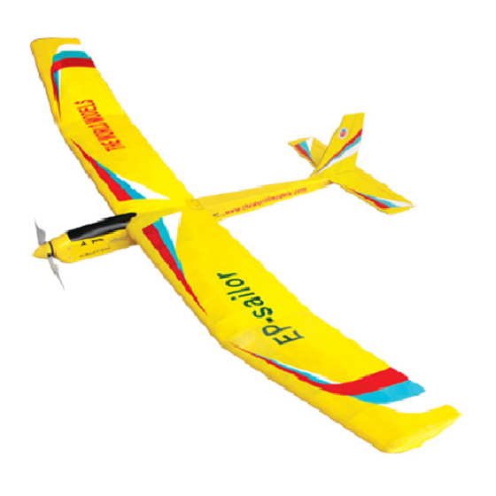
E P - S a i l o r
E P - S a i l o r
Requires 3 channel radio with 2 mini servos, 30A speed
controller with brake and 7 cell 1800 mAh hump pack battery.
Wing Span
Wing Area
Flying Weight
Fuselage Length
Warning! This model is not a toy.
It is designed for maximum performance. Please seek advice if one is not familiar with this kind
of electric powered precision model. Operating this model without prior preparation may cause
injuries. Remember, safety is the most important thing. Always keep this instruction manual at
hand for quick reference.
E1590311
Speed 450 motor
*Specifications are subject to change without notice.*
The World Models
Manufacturing Co., LTD.
www.theworldmodels.com
Specifications
78 in/1980 mm
665 sq in/42.9 sq dm
3.0 lbs/1380 g
40.5 in/1035 mm
INSTRUCTION MANUAL
FACTORY PRE-FABRICATED
ALMOST-READY-TO-FLY(ARF) SERIES
MADE IN CHINA
Advertisement
Table of Contents

Related Manuals for THE WORLD MODELS EP-Sailor


Summary of Contents for THE WORLD MODELS EP-Sailor
- Page 1 Operating this model without prior preparation may cause injuries. Remember, safety is the most important thing. Always keep this instruction manual at hand for quick reference. FACTORY PRE-FABRICATED The World Models ALMOST-READY-TO-FLY(ARF) SERIES Manufacturing Co., LTD. MADE IN CHINA www.theworldmodels.com...
-
Page 2: Before You Begin
EP-Sailor EP-Sailor I N D E X BEFORE YOU BEGIN PARTS LIST ASSEMBLY P.3-9 SAFETY PRECAUTIONS BEFORE YOU BEGIN Read through the manual before you begin, so you will have an overall idea of what to do. Check all parts. If you find any defective or missing parts contact your local dealer. Please DRY FIT and check for defects for all parts that will require CA or Epoxy for final assembly. - Page 3 Parts list 1.FUSELAGE -- 1 pc. SCREW PM2.5 X 12mm -- 2 pcs SCREW PM2.5 X 16mm -- 2 pcs 2.MAIN WING -- 1 set SOCKET HEAD SCREW M3 X 8mm -- 2 pcs 3.STABILIZER & ELEVATOR -- 1 set WASHER d2.5 x D8mm -- 2 pcs WASHER d3 X D7mm -- 2 pcs 4.VERTICAL FIN &...
- Page 4 Main Wing Wing Tube Ø9.5 x 373mm Completed Stabilizer Bottom View Apply instant type CA glue to both sides of each hinge. Completed E1590311...
- Page 5 Vertical Fin / Stabilizer Apply instant type CA glue to both sides of each hinge. Peel off shaded Portion covering film. Completed E1590311...
-
Page 6: Elevator Pushrod
Elevator Pushrod Ø1mm pilot holes for World Models tri-horn are Screw pre-drilled. Please look for pin-hole marks at PM2 x 12mm under side of control surfaces. Horn Fuel Tube Ø6 x 5mm Clevis Metal Rod PM2 x 12mm PM2 x 12mm 1.6 x 670mm Metal Rod 1.6 x 670mm... - Page 7 Motor / Cowling Setting Screw M3 x 8mm Screw PM2.5 x 12mm Screw PM2 x 16mm Screw PWA2.3 X 8mm Screw PA2.6 X 12mm Washer d3 x D7mm M3 x 8mm d3 x D7mm Set Screw TO ALLOW FOR BACKLASH OF MATCHING GEAR, PUT A PIECE OF THIN PAPER...
-
Page 8: Radio Equipment
Radio Equipment Install and arrange the servo as shown in the diagram. Elevator Pushrod Elevator Servo Battery Tie Speed 550 Motor Straper Fuel Tube Sponge Double-Side Tape Ø6 x 5mm 30A Speed Controller Rudder Servo Rudder Pushrod Main Wing Screw PM2.5 x 16mm PM2.5 x 16mm d2.5 x D8mm... - Page 9 Wing Setting A=A' B=B' C=C' Adjust the wing and fuselage configuration as in the diagrams. E1590311...
-
Page 10: Control Throws
Control Throws Adjust the control throws as shown in the diagram.These throws are good for general Rudder flying. You can adjust according to your 30mm personal preference. 30mm Elevator 15mm 15mm C.G. C.G. 75mm 2.95in. The ideal C.G. position is 75mm (2.95 in.) behind the leading edge measured at where the wing meets the fuselage. - Page 11 E1590311...
- Page 12 The World Models Manufacturing Co., LTD. www .thew orldm odels .com E1590311...
Need help?
Do you have a question about the EP-Sailor and is the answer not in the manual?
Questions and answers