Table of Contents
Advertisement
Quick Links
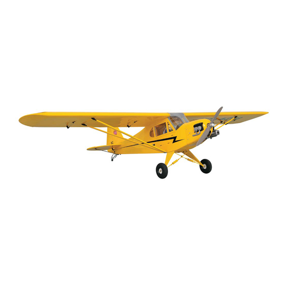
Requires : 0.91 cu. in. displacement 2-stroke
Wing Span
Wing Area
Flying Weight
Fuselage Length
Warning ! This model is not a toy.
It is designed for maximum performance. Please seek advice if one is not familiar with this kind
of electric powered precision model. Operating this model without prior preparation may cause
injuries. Remember, safety is the most important thing. Always keep this instruction manual at
hand for quick reference.
A053PO28891307
1.20 - 1.60 cu. in. displacement 4-stroke
4-channel radio w/ 4 high torque servos
and 1 standard servo(throttle)
* Specifications are subject to change without notice.*
The World Models
Manufacturing Co., Ltd.
www.theworldmodels.com
Specifications
104.0 in / 2640 mm
1586 sq in / 102.3 sq dm
14.0-16.0 lbs / 6400-7300 g
65.0 in / 1650 mm
INSTRUCTION MANUAL
FACTORY PRE-FABRICATED
ALMOST-READY-TO-FLY(ARF)SERIES
MADE IN CHINA
Advertisement
Table of Contents

Related Manuals for THE WORLD MODELS 1/4 Piper J-3 Cub


Summary of Contents for THE WORLD MODELS 1/4 Piper J-3 Cub
- Page 1 Operating this model without prior preparation may cause injuries. Remember, safety is the most important thing. Always keep this instruction manual at hand for quick reference. The World Models FACTORY PRE-FABRICATED Manufacturing Co., Ltd. ALMOST-READY-TO-FLY(ARF)SERIES MADE IN CHINA www.theworldmodels.com...
-
Page 2: Parts List
INDEX BEFORE YOU BEGIN PARTS LIST ASSEMBLY P.3-P.13 SAFETY PRECAUTIONS P.13 BEFORE YOU BEGIN Read through the manual before you begin, so you will have an overall idea of what to do. Check all parts. If you find any defective or missing parts contact your local dealer. Please DRY FIT and check for defects for all parts that will require CA or Epoxy for final assembly. - Page 3 Parts List 1. MAIN WING -- 1 pair 13. TAIL GEAR ASSEMBLY 11-22LBS PL3410021 -- 1 set SCREW PA3x14mm -- 3 pcs 2. PUSHROD Ø1.8x120mm w/ Threads(For Aileron Servo) -- 2 pcs SCREW PWA2x12mm -- 3 pcs FUEL TUBE Ø6x5mm -- 4 pcs ALUMINIUM PLATE(For Staying on Tail Fuselage Bottom) 1.5x10x34mm -- 1 pc.
-
Page 4: Aileron Servo
Main Wing Aileron Servo Lead Pre-glued Bottom View Aileron Servo Ø1mm pilot holes for World Models tri-horn are pre-drilled. Please look for pin-hole marks at under side of control surfaces. Screw PB2x30mm TWM PL8210010 CLEVIS WRENCH Screw PWA2x8mm PWA2x8mm Fuel Tube Straper 6x5mm Ø... -
Page 5: Fuel Tank
Main Wing 202mm 193mm (7.95in.) (7.59in.) M3x15mm Socket Head Screw 69mm (2.72in.) M3x15mm d3xD7mm Main Wing Strut 380mm 369mm (14.96in.) (14.52in.) Washer d3xD7mm Washer M3 Nylon Insert Lock Nut M3 Nylon Insert Lock Nut M3x15mm d3xD7mm Washer Bottom View Fuel Tank Cable Tie (For Fuel Tank) 1.5x5x400mm... - Page 6 Engine Mount M4x30mm Socket Head Screw 5.5mm Engine Mount d4.2xD14.5mm Washer PL5111080 M4 Blind Nut Washer d4.2xD14.5mm Socket Head Screw M4x30mm Engine M4x35mm M3 NYLON M4 NYLON INSERT LOCK NUT Socket Head Screw INSERT LOCK Nut d4xD12mm Washer KM3x20mm Screw M4 NYLON INSERT LOCK Nut d4xD12mm Washer...
-
Page 7: Main Landing Gear
Cowling Please refer to the attached sheet for usage of the transparent 3D template. First insert the grommet to the cowling then apply screw. PWA2.6x12mm Screw d1.5xD6.5mm PWA2.6x12mm Silicon Grommet d1.5xD6.5mm Silicon Grommet PWA2.6x12mm 2.5mm 2.5mm 2.5mm 2.5mm PWA2.6x12mm Cowling Wing Struts Mounting Bracket M3x14mm Wa sh e r... - Page 8 Main Landing Gear PM3x13mm PA1.7x8mm Screw Washer Wire Bracket d3xD7mm Washer d3xD7mm PM3x13mm Screw 3.1mm 3.1mm PM3x13mm d3xD7mm Washer M3 Nut 3mm Set Screw PA1.7x8mm M3 Nut 3.1mm 3.1mm 4.6mm Wheel Collar Bottom View Stabilizer & Elevator Temporary install the main wing, adjust leveling of the stabilizer to make it as (Stabilizer) parallel to the main wing as possible.
-
Page 9: Rudder Pushrod
Set Scr Copper Plate M2 Nut 1x10x34mm Ø1mm pilot holes for The World Models tri-horn are pre-drilled. Rudder Pushrod Please look for pin-hole marks at under side of control surfaces. PB2x16mm Screw Cl ev i s Fu el Tu b e Pushrod Ø6x 5m m... -
Page 10: Elevator Pushrod
Ø1mm pilot holes for The World Models tri-horn are pre-drilled. Elevator Pushrod Please look for pin-hole marks at under side of control surfaces. PB2x16mm Screw PB2x16mm Pushrod Ø1.8x995mm Tri-horn M3x22mm Clevis TWM PL8210010 Fuel Tube CLEVIS WRENCH Ø6x5mm Servo Set... -
Page 11: Radio Equipment
Radio Equipment J1(Pushrod Ø1.8x85mm) Elevator Pushrod Ø1.8x85mm M2 Nut Pushrod Connector Install and arrange the servos J2(Pushrod Ø1.8x995mm) as shown in the diagram. Elevator Servo KM2x8mm To Throttle Throttle Servo Straper Receiver Fuel Tank Elevator Servo 450cc Fuel Tube Battery Ø6x5mm Rudder Servo Sponge 10x80x200mm... - Page 12 Main Wing Set Screw x 8mm Wing Tube Lead to Aileron Servo D16x661mm Wire Ø0.8mm Set Screw Completed Self Tightening Set Screw M3X8mm Wing Latch Completed Wing Tube Main Wing M3x8mm Socket Head Screw d3xD7mm Washer M3 Nylon Inert Lock Nut M3 Nylon Inert Lock Nut Washer d3xD7mm...
-
Page 13: Control Throws
Wing Setting A=A’ B=B’ C=C’ D=D’ Control Throws Adjust the control throws as shown in the diagram. These throws are good for general flying. You can adjust according Rudder to your personal preference. 55mm 55mm Elevator 40mm 40mm Aileron 20mm 20mm C.G. - Page 14 # Pre-flight adjustment must be done before flying, it is very dangerous to fly a badly pre-adjusted aircraft. # 1/4 Piper J-3 Cub is specially designed to be powered by 2C 0.91 or 4C 1.20 - 1.60 engine, using a morepowerful engine does not mean better performance. In fact, over powered engine may cause severe damage and injuries.
- Page 15 LINKAGE CONNECTOR HW7111050 & HW7111060 Drill 2mm hole at servo horn. Insert linkage connector into servo horn. Make sure shoulder of screw is cleared from servo horn. Add washer to reduce play if necessary. Shoulder Tighten up the round nut against the shoulder.
- Page 16 Product Registration Form (US Customers) We would like to share with you any relevant information regarding your model, including product news and free upgrade parts when applicable. Please fill in the following and send to AirBorne Models, 4749-K, Bennett Drive, Livermore, CA 94551 USA. 1.
- Page 17 Usage of the transparent 3D template This transparent 3D template is used for position guidance of the actual cutting of the pre-painted cowling. Simply cut the transparent 3D template to fit your engine and exhaust pipe, then slide onto the actual cowling and use as template to mark the openings required for final cutting.
- Page 18 180mm Extension Fuel Filter Package Package Code No. Size Code No. Size Package Code No. Size Package Code No. Size Large Clevis Small Clevis Special tool for clevis installation. Suitable for standard and small Package Code No. Size (EP)clevis. KP0041300 Code No SV4031 Package Code No.
- Page 19 Silicon Tubes Wind sock Package Package Code No. Size Code No. AT3001052 Size PT1113040 D4xd2mm 1m(Transparent) AT3001052 D260x900mm 1 pc PT1113060 D6xd2.5mm 1m(Transparent blue) PT1113082 D6xd3.2mm 1m(Red) (transparent blue) (red) (transparent) Adjustable Wheel Chock Code No. Size Package Fuel Filter MS6120040 D40-90mm (wheel) 1 pr Package...
- Page 20 A053PO28891307...
Need help?
Do you have a question about the 1/4 Piper J-3 Cub and is the answer not in the manual?
Questions and answers