Table of Contents
Advertisement
Quick Links
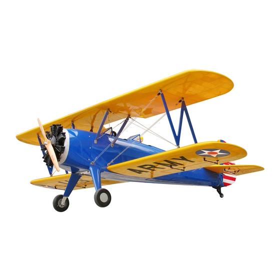
Requires: 100 c.c. gasoline engine,
Wing Span
Wing Area
Flying Weight
Fuselage Length
Warning! This model is not a toy.
It is designed for maximum performance. Please seek advice if one is not familiar with this kind
of engine powered precision model. Operating this model without prior preparation may cause
injuries. Remember, safety is the most important thing. Always keep this instruction manual at
hand for quick reference.
The World Models
Manufacturing Co., Ltd.
www.theworldmodels.com
A300PO30601412
4-channel radio w/ 9 high torque servos.
Specifications
*Specifications are subject to change without notice.*
116 in / 2950 mm
3700 sq in / 238.7 sq dm
38.5 Ib / 17.5 kg
88 in / 2240 mm
ALMOST-READY-TO-FLY(ARF)SERIES
INSTRUCTION MANUAL
( A300 )
FACTORY PRE-FABRICATED
MADE IN CHINA
Advertisement
Table of Contents

Subscribe to Our Youtube Channel
Related Manuals for THE WORLD MODELS 30% Stearman PT-17


Summary of Contents for THE WORLD MODELS 30% Stearman PT-17
- Page 1 Operating this model without prior preparation may cause injuries. Remember, safety is the most important thing. Always keep this instruction manual at hand for quick reference. FACTORY PRE-FABRICATED The World Models ALMOST-READY-TO-FLY(ARF)SERIES Manufacturing Co., Ltd. MADE IN CHINA www.theworldmodels.com...
- Page 2 INDEX BEFORE YOU BEGIN PARTS LIST ASSEMBLY P.3-P.15 SAFETY PRECAUTIONS P.15 BEFORE YOU BEGIN Read through the manual before you begin, so you will have an overall idea of what to do. Check all parts. If you find any defective or missing parts contact your local dealer. Please DRY FIT and check for defects for all parts that will require CA or Epoxy for final assembly.
- Page 3 Parts List 1. DECALS: A300 DEC -- set PLASTIC TUBE d2.5xD4x360mm -- 1 pc. LOWER WING -- 1 pair SCREW PWA2.6x8mm -- 4 pcs VERTICAL FIN & RUDDER -- 1 set PLYWOOD 3x104.4x185mm -- 1 pc. FUSELAGE -- 1 pc. COWLING -- 1 set 10.
- Page 4 Decals Cut out decal sheet, peel off backing sheet and apply on fuselage and wings. Decal Lower wings Rudder Right View Left View Fuselage Left View Right View A300PO30601412...
- Page 5 Tail Piece Covering Vertical Fin & Rudder M4x120mm Threaded Rod PM2.5x21mm Screw Nylon Insert Lock Nut M2.5 Swivel Clevis Horn Fairing M4 x 120mm M2.5 Nut M4 Nylon Insert Lock Nut PM2 x 10mm Heavy Duty Horn Bracket PA1.7 x 8mm M2 Nut PM2.5 x 21mm Swivel Clevis Horn Support...
- Page 6 Stabilizer & Elevator HM4x45mm Button Head Screw Servo wire PWA2.3x8mm Screw Nylon Insert Lock Nut d4.5xD9mm Washer Pre-glued A=A' AluminumTube 14.5x317mm Ø Bottom View The hinges are factory glued. M2x8mm Socket Head Screw PL4120300 1.5mm M2 Nut PWA2.3x8mm M2 Nylon Insert Lock Nut Heavy Duty Clevis...
- Page 7 Tail Landing Gear PWA2.3x12mm Screw PA3.5x16mm Fuel Tube D6x5mm PWA2.3x12mm Straper Flying Wire HM4x30mm Button Head Screw HM4x25mm Button Head Screw Nylon Insert Lock Nut d4.5xD9mm Washer Press down the center 1/3 portion Wire Copper Tube M4 Nylon Insert Lock Nut Washer d4.5xD9mm HM4x30mm Copper Tube...
-
Page 8: Main Landing Gear
Main Landing Gear M6x30mm Socket Head Screw HM4x12mm Button Head Screw HM4x6mm Button Head Screw PA1.7x8mm Screw Nylon Insert Lock Nut d6xD15mm Washer d4xD9mm Washer Washer HM4x6mm d4xD9mm Washer d6xD15mm M6x30mm M3x3mm M8 Nylon Set Screw Insert Lock 5.1mm Collar HM4x16mm Washer Ø5x58mm... - Page 9 Please refer to your engine instruction manual for the installation of engine ignition Engine unit and battery, some engine manufacturer may prefer installing them inside the fuselage to avoid heat from the engine 200mm M6x50mm Socket Head Screw 7.9 in. PWA2.6x8mm Screw d6xD15mm...
- Page 10 Servo Set 3x3mm Set Screw 3x3mm Set Screw Throttle Pushwire Linkage Connector Washer Washer Washer 1.5mm Throttle Servo M2 Nut Please refer to the attached sheet for linkage connector installation. Servos Setting Sponge Charge Receptacles Receiver 10x80x200mm KP0041300 Throttle Servo Battery Install and arrange the servo as shown in the diagram.
- Page 11 Lower Wing M4x65mm Socket Head Screw PWA2.3x8mm Screw Nylon Insert Lock Nut Pre-glued A ileron Servo Lead Bottom View The hinges are factory glued. M2x8mm Socket Head Screw PL4120300 1.5mm M2 Nut PWA2.3x8mm M2 Nylon Insert Lock Nut Heavy Duty Clevis M2 x 10mm Pushrod...
- Page 12 Lower Wing Propeller Cover Wing Tube 32x762mm Ø Cockpit Completed Upper Wing Wing Tube 32x1029.5mm Ø Completed A300PO30601412 P.11...
- Page 13 Wing Struts M4x340mm Threaded Rod M4x320mm Threaded Rod HM4x25mm Button Head Screw HM4x16mm Button Head Screw HM4x25mm Threaded Rod M4x340mm Nylon Insert Lock Nut d4.5xD9mm Washer Washer d4.5xD9mm HM4x16mm M4 Nylon Insert Lock Wing Struts Mounting Plate 1.5x10x35mm(130°) Mounting Plate 1.5x20x35mm(119°) M4x320mm Washer...
- Page 14 Flying Wire Press down the center 1/3 portion Wire Copper Tube M2x10mm Heavy Duty Clevis Copper Tube M2 Nylon Insert Lock Nut Eye Screw Wire Steel Wire M3 Nut Copper Tube Turn Buckles Wire Plywood Ø 8x230mm A300PO30601412 P.13...
-
Page 15: Control Throws
Canopy & Pilots PWA2.3x8mm Screw d1.5xD6.5mm Silicon Grommet Canopy Pilot PWA2.3x8mm Cable Tie 2.5x5x300mm Silicon Grommets Fuselage Control Throws Adjust the control throws as shown in the diagram. These throws are good for general flying. You can adjust according to your personal preference. Elevator 35mm 35mm... - Page 16 C.G. The ideal C.G. position is 210mm (8.25 in.) behind the leading edge measured at where the wing meets the fuselage. In order to obtain the C.G. specified, add weight to the fuselage or move the battery position. Check the C.G. before flying. 210mm 8.25 in.
- Page 17 LINKAGE CONNECTOR HW7111050 & HW7111060 Drill 2mm hole at servo horn. Insert linkage connector into servo horn. Make sure shoulder of screw is cleared from servo horn. Add washer to reduce play if necessary. Shoulder Tighten up the round nut against the shoulder.
-
Page 18: Optional Parts
Optional Parts ACCESSORIES) Field Stand 180mm Extension Code No. Size Package Code No. Size Package KW0011800 180mm 1 set MS9111450 600 x 240 x 350mm 1 pc 180mm Y-Cord Code No. Size Package KW0021800 180mm 1 pc Neoprene Tube Code No. Size Package PT1114050... - Page 19 A300PO30601412...
- Page 20 The World Models Manufacturing Co., Ltd. www.theworldmodels.com A300PO30601412...
Need help?
Do you have a question about the 30% Stearman PT-17 and is the answer not in the manual?
Questions and answers