Table of Contents
Advertisement
Quick Links
0.52-0.72 cu.in. displacement 4-stroke
requires: 4-channel radio w / 5 standard servos
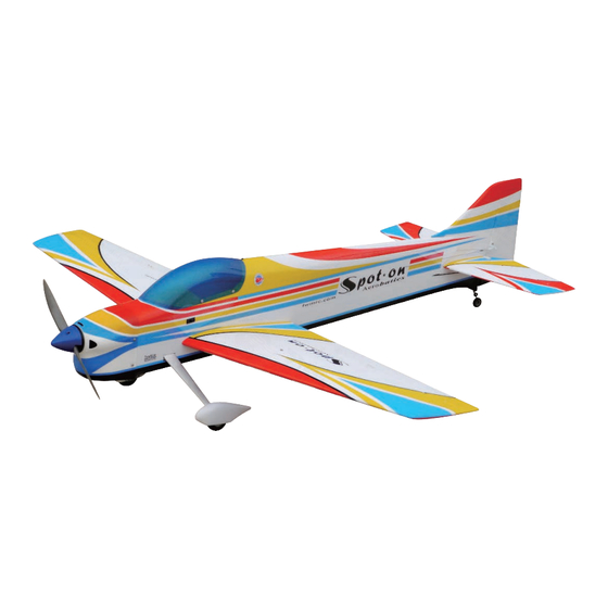
Wing Span
Wing Area
Flying Weight
Fuselage Length
Warning! This model is not a toy.
It is designed for maximum performance. Please seek advice if one is not familiar with this kind
of engine powered precision model. Operating this model without prior preparation may cause
injuries. Remember, safety is the most important thing. Always keep this instruction manual at
hand for quick reference.
The World Models
Manufacturing Co., Ltd.
www.theworldmodels.com
A249HPO31231510
Specifications
53.5 in / 1360 mm
538 sq in / 34.7 sq dm
5.8 Ib / 2650 g
57 in / 1450 mm
*Specifications are subject to change without notice.*
INSTRUCTION MANUAL
FACTORY PRE-FABRICATED
ALMOST-READY-TO-FLY(ARF)SERIES
MADE IN CHINA
( A249H )
Advertisement
Table of Contents

Related Manuals for THE WORLD MODELS Spot-On 50


Summary of Contents for THE WORLD MODELS Spot-On 50
- Page 1 Operating this model without prior preparation may cause injuries. Remember, safety is the most important thing. Always keep this instruction manual at hand for quick reference. FACTORY PRE-FABRICATED The World Models ALMOST-READY-TO-FLY(ARF)SERIES Manufacturing Co., Ltd. MADE IN CHINA www.theworldmodels.com...
-
Page 2: Before You Begin
INDEX BEFORE YOU BEGIN PARTS LIST ASSEMBLY P.3-P.10 SAFETY PRECAUTIONS P.11 BEFORE YOU BEGIN Read through the manual before you begin, so you will have an overall idea of what to do. Check all parts. If you find any defective or missing parts contact your local dealer. Please DRY FIT and check for defects for all parts that will require CA or Epoxy for final assembly. -
Page 3: Parts List
Parts List 1. STABILIZER & ELEVATOR -- 1 set WASHER d3.5xD8mm -- 8 pcs FUSELAGE -- 1 pc. THROTTLE PUSHROD Ø1.2x410mm -- 1 pc. PLASTIC TUBE d2xD3x180mm -- 1 pc. 2. VERTICAL FIN & RUDDER -- 1 set COWLING --1 pc. TRANSPARENT 3D TEMPLATE -- 1 pc. -
Page 4: Stabilizer & Elevator
Stabilizer & Elevator Apply instant type CA glue to both sides of each hinge. (Stabi l i zer) (Mai n Wi ng) B=B' Temporary install the main wing, adjust leveling of the stabilizer to make it as parallel to the main wing as possible Vertical Fin &... -
Page 5: Elevator Pushrod
Elevator Pushrod PB2x14mm Screw Pushrod PB2x14mm Ø1.8x832mm Fuel Tube D6x5mm Clevis Horn Ø1mm pilot holes for World Models horn are pre-drilled. Please look for pin-hole marks at under side of control surfaces. Tail Landing Gear PA3x12mm Screw 2.1mm Collar Ø25mm PA3x12mm 2.1mm Collar 3mm set screw... - Page 6 Engine d4.5xD9mm M4x25mm M4x25mm Socket Head Screw M3.5x30mm Socket Head Screw Engine Mount PL5111050 PWA2.6x12mm Screw PA3x12mm Screw d1.5xD6.5mm Silicon Grommet Screw M3.5 M3.5 Nut d3.5xD8mm Washer d3.5xD8mm M3.5x30mm Washer d4.5xD9mm 3x3mm Throttle Pushrod Ø1.2x410mm Plastic Tube d2xD3x180mm Throttle Pushrod Throttle Servo Washer Washer...
-
Page 7: Aileron Servo
Aileron Servo PWA2x8mm Screw Servo Mounting Panel PWA2x8mm 1.5mm Servo lead 1.5mm Bottom View Apply instant type CA glue to both sides of each hinge. Aileron Pushrod PB2x22mm Screw Fuel Tube Straper D6x5mm Pushrod Ø1.8x80mm PB2x22mm Fuel Tube D6x5mm Clevis Horn Ø1mm pilot holes for World Models horn are pre-drilled. - Page 8 Main Wing M3x20mm Socket Head Screw PA3x20mm Screw d3xD7mm Washer M3x20mm d3xD7mm Washer Wing Tube d14xD16x465mm Insert carbon wing tube into right wing, apply the Socket Head Screw. PA3x20mm d3xD7mm Insert the right wing tube through the Fuselage, and then install the left wing. Press the wings against the fuselage then apply PA screw to the left wing.
- Page 9 Radio 180mm Y-Cord Aileron Servo (L) Elevator Servo Aileron Servo (R) Throttle Servo Rudder Servo Press down the center 1/3 portion W i re Receiver Plug in the Aileron Servos wire to channel 1 Plug in the Elevator Servo wire to channel 2 Plug in the Throttle Servo wire to channel 3 C o p p e r Tu b e Plug in the Rudder Servo wire to channel 4...
- Page 10 Canopy PWA2.3x8mm Screw Double - sided Tape d1.5xD6.5mm Silicon Grommet Canopy PWA2.3x8mm Fuselage Silicon Grommets Wing Setting A=A` B=B` C=C` A249HPO31231510...
-
Page 11: Control Throws
Control Throws Adjust the control throws as shown in the diagram. These throws are good for general flying. You can adjust according to your personal preference. Elevator 18mm 18mm Rudder 45mm 45mm Ailerons ( away from fuselage ) 10mm 10mm C.G. - Page 12 Warning! Important Safety Precautions # First time flyer should never fly by himself / herself. Assistance from experienced flyer is absolutely necessary. # Pre-flight adjustment must be done before flying, it is very dangerous to fly a badly pre-adjusted aircraft. 4C 0.52-0.72 engine, using a more is specially designed to be powered by powerful engine does not mean better performance.
- Page 13 LINKAGE CONNECTOR HW7111050 & HW7111060 Drill 2mm hole at servo horn. Insert linkage connector into servo horn. Make sure shoulder of screw is cleared from servo horn. Add washer to reduce play if necessary. Shoulder Tighten up the round nut against the shoulder.
- Page 14 Usage of the transparent 3D template This transparent 3D template is used for position guidance of the actual cutting of the pre-painted cowling. Simply cut the transparent 3D template to fit your engine and exhaust pipe, then slide onto the actual cowling and use as template to mark the openings required for final cutting.
-
Page 15: Optional Parts
Optional Parts ACCESSORIES) 180mm Extension Clevis Wrench Code No. Size Package Code No. Size Package PL8210010 1 set KW0011800 180mm 1 set Large Clevis Small Clevis Special tool for clevis installation. Suitable for standard and small (EP) clevis. 180mm Y-Cord Code No. - Page 16 A249HPO31231510...
Need help?
Do you have a question about the Spot-On 50 and is the answer not in the manual?
Questions and answers