Table of Contents
Advertisement
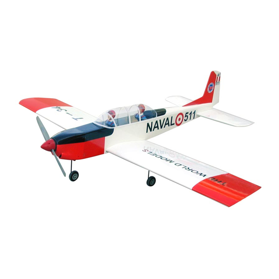
Requires: 0.40-0.55 cu. in. displacement 2-stroke
Wing Span
Wing Area
Flying Weight
FuseLage Length
Warning! This model is not a toy.
It is designed for maximum performance. Please seek advice if one is not familiar
with this kind of engine powered precision model. Operating this model without
prior preparation may cause injuries. Remember, safety is the most important thing.
Always keep this instruction manual at hand for quick reference.
A052PO29361307
0.52-0.56 cu. in. displacement 4-stroke
4-channel radio w/ 5 standard servos
* Specifications are subject to change without notice.*
The World Models
Manufacturing Co., LTD.
www.theworldmodels.com
Specifications
58.0 in / 1470 mm
577 sq in / 37.2 sq dm
5.0-5.5 lbs / 2200-2500 g
48.0 in / 1220 mm
INSTRUCTION MANUAL
FACTORY PRE-FABRICATED
ALMOST-READY-TO-FLY(ARF)SERIES
MADE IN CHINA
Advertisement
Table of Contents

Related Manuals for THE WORLD MODELS T-34 Mentor


Summary of Contents for THE WORLD MODELS T-34 Mentor
- Page 1 Operating this model without prior preparation may cause injuries. Remember, safety is the most important thing. Always keep this instruction manual at hand for quick reference. The World Models FACTORY PRE-FABRICATED Manufacturing Co., LTD.
- Page 2 INDEX BEFORE YOU BEGIN PARTS LIST ASSEMBLY P.3-P.10 SAFETY PRECAUTIONS P.10 BEFORE YOU BEGIN Read through the manual before you begin, so you will have an overall idea of what to do. Check all parts. If you find any defective or missing parts contact your local dealer. Please DRY FIT and check for defects for all parts that will require CA or Epoxy for final assembly.
- Page 3 Parts List 12. COWLING -- 1 pc. 1. MAIN WING -- 1 pair TRANSPARENT 3D TEMPLATE -- 1 pc. 2. SCREW PB2x14mm -- 4 pcs SCREW PWA2.6x12mm -- 4 pcs SCREW PB2x10mm -- 2 pcs SILICON GROMMET d1.5xD6.5mm -- 4 pcs SCREW PWA2x8mm -- 8 pcs SPINNER Ø57mm PL2111057 -- 1 set CLEVIS PL4112103 -- 2 pcs...
-
Page 4: Aileron Servo
Main Wing Aileron Servo Lead Pre-glued Bottom View Aileron Servo PB2x14mm Screw PB2x10mm Screw PWA2x8mm Screw TWM PL8210010 CLEVIS WRENCH Ø1mm pilot holes for World Models tri-horn are pre-drilled. Please look for pin-hole marks at under side of control surfaces. Straper Fuel Tube Ø6x5mm... -
Page 5: Main Landing Gear
Please dry fit wing joiner into left and right wing to make sure they fit with the Main Wing proper dihedral angle, mark the wing joiner if necessary. Apply epoxy glue to both sides of all surfaces in contact. Use a stick to apply the glue to inner side of wing joiner sleeve, and apply the glue to wing joiner before putting them together. -
Page 6: Fuel Tank
Stabilizer & Elevator PA3x25mm Screw PA3x25mm d3xD12mm Washer d3xD12mm Washer (Stabilizer) Pre-glued (Main Wing) Temporary install the main wing, adjust leveling of the stabilizer to make it as parallel to the main wing as possible. Bottom View Vertical Fin & Rudder c = c' Pre-glued Fuel Tank... -
Page 7: Front Wheel
Engine Mount M3x25mm Socket Head Screw Engine Mount PL51111030 d3xD7mm Washer d3xD7mm Washer M3x25mm Blind nuts are off-centered to keep the spinner at the fuselage axis. Front Wheel 4.1mm Collar 4.1mm Collar 3mm Set Screw 3mm Set Screw 4.1mm Collar Front View Completed Engine... -
Page 8: Rudder Pushrod
Please refer to the attached sheet for usage of the Cowling transparent 3D template. PWA2.6x12mm Screw PWA2.6x12mm d1.5xD6.5mm Silicon Grommet Install the cowling as shown on the drawing to allow for 5~7mm clearance between drive, washer surface and tip of cowling. 3.5mm d1.5xD6.5mm Silicon Grommet... -
Page 9: Radio Equipment
Servo Set 3x3mm Set Screw Throttle Pushwire Linkage Connector M2 Nut 2mm Washer 1.5mm Throttle Servo M2 Nut Please refer to the attached sheet for linkage connector installation. Servos Rudder Pushrod Balsa 9x9x104mm Elevator Pushrod Straper Fuel Tube Ø6x5mm Plywood 6x82x117mm Front Wheel Pushwire Ø1.2x430mm... - Page 10 Canopy First insert the grommet to the canopy then apply screw. PWA2.3x8mm Screw d1.5xD6.5mm Silicon Grommet PWA2.3x8mm d1.5xD6.5mm Silicon Grommet Apply double-sided tape Pilot Main Wing M3x25mm d3xD12mm Socket Head Screw M3x25mm d3xD12mm Washer PLYWOOD 3x45x90mm Bottom View Wing Setting Adjust the wing and fuselage configuration as shown in the diagrams.
-
Page 11: Control Throws
Adjust the control throws as shown in the diagram. Control Throws These throws are good for general flying. You can adjust according to your personal preference. Elevator 12mm 12mm Rudder 20mm 20mm Ailerons The ideal C.G. position is 78mm (3.07in.) behind the leading edge measured at where the wing C.G. - Page 12 LINKAGE CONNECTOR HW7111050 & HW7111060 Drill 2mm hole at servo horn. Insert linkage connector into servo horn. Make sure shoulder of screw is cleared from servo horn. Add washer to reduce play if necessary. Shoulder Tighten up the round nut against the shoulder.
- Page 13 Usage of the transparent 3D template This transparent 3D template is used for position guidance of the actual cutting of the pre-painted cowling. Simply cut the transparent 3D template to fit your engine and exhaust pipe, then slide onto the actual cowling and use as template to mark the openings required for final cutting.
- Page 14 A052PO29361307...
- Page 15 A052PO29361307...
- Page 16 A052PO29361307...
Need help?
Do you have a question about the T-34 Mentor and is the answer not in the manual?
Questions and answers