Table of Contents
Advertisement
Quick Links
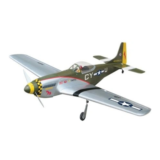
P-51 MUSTANG EP (40)
Requires: 5-channel radio w/ 5 mini servos,
Wing Span
Wing Area
Flying Weight
Fuselage Length
Warning ! This model is not a toy.
It is designed for maximum performance. Please seek advice if one is not familiar with this kind
of electric powered precision model. Operating this model without prior preparation may cause
injuries. Remember, safety is the most important thing. Always keep this instruction manual at
hand for quick reference.
E287XMPO17530807
450W Motor System
Outrunner Motor KM0374810,
w/ Propeller Adaptor HW2340300, 40A
Brushless ESC with 11x8E propeller, 4 cells
14.8V 3200 mAh Li - Po battery & charger.
*Specifications are subject to change without notice.*
The World Models
Manufacturing Co., Ltd.
www.theworldmodels.com
Specifications
49 in / 1250 mm
434 sq in / 28 sq dm
3.6 Ib / 1650 g
43 in / 1090 mm
INSTRUCTION MANUAL
FACTORY PRE-FABRICATED
ALMOST-READY-TO-FLY(ARF)SERIES
MADE IN CHINA
Advertisement
Table of Contents

Related Manuals for THE WORLD MODELS P-51 MUSTANG EP


Summary of Contents for THE WORLD MODELS P-51 MUSTANG EP
-
Page 1: Specifications
INSTRUCTION MANUAL P-51 MUSTANG EP (40) 450W Motor System Requires: 5-channel radio w/ 5 mini servos, Outrunner Motor KM0374810, w/ Propeller Adaptor HW2340300, 40A Brushless ESC with 11x8E propeller, 4 cells 14.8V 3200 mAh Li - Po battery & charger. - Page 2 P-51 MUSTANG EP (40) I N D E X BEFORE YOU BEGIN P. 1 P. 2 PARTS LIST P.3-P.11 ASSEMBLY SAFETY PRECAUTIONS P.11 BEFORE YOU BEGIN Read through the manual before you begin, so you will have an overall idea of what to do.
- Page 3 Parts List 1. MAIN WING -- 1 pair 12. STRAPER -- 2 pcs FUEL TUBE d2xD4x4mm-- 2 pcs 2. RETRACT GEAR COVER-- 1 pair SPONGE 10x50x150mm -- 1 pc. BATTERY TIE 200mm -- 1 pc. 3. WING JOINER 6x16x126 -- 1 pc. DOUBLE-SIDED TAPE 30x35mm -- 1 pc.
-
Page 4: Retractable Landing Gear
Main Wing Apply instant type CA glue to both sides of each hinge. Completed Aileron Servo Lead Bottom View Retractable Landing Gear Bottom View Please dry fit wing joiner into left and right wing to make sure they fit with the Main Wing proper dihedral angle, mark the wing joiner if necessary. -
Page 5: Aileron Servo
Retract Servo Please refer to attached sheet for linkage connector installation. Linkage connector To R-Side To L-Side Wheels Down Position 16mm Travel 16mm Travel Wheels Up Position Aileron Servo Ø1mm pilot holes for World Models tri-horn are pre-drilled. Please look for pin-hole marks at under side of control surfaces. Balsa Wood PA1.7x8mm Screw 7x8x13mm... - Page 6 Stabilizer & Elevator Temporary install the main (Stabi l i zer) wing, adjust leveling of the stabilizer to make it as (Mai n Wi ng) parallel to the main wing as Apply instant type CA glue to both sides of each hinge. B=B' possible.
-
Page 7: Elevator Pushrod
Tail Landing Gear PA2.6x12mm PA2.6x12mm Screw PA2.6x12mm PM2x10mm Screw M2 Nut set screw 1.7mm Collar M2 Nut Steering Bracket Bottom View PM2x10mm Elevator Pushrod Ø1mm pilot holes for World Models tri-horn are pre-drilled. PB2x10mm Screw Please look for pin-hole marks at under side of control surfaces. Fuel Tube PB2x10mm d2xD4x4mm... - Page 8 Outrunner Motor / Cowling / Spinner M3x12mm Socket Head Screw Optional Parts Motor Mount PL5404000 d3xD7mm Washer Outrunner 37/48 Deluxe KM0374810 Radial Mount Adaptor Set PWA2.3x8mm Screw Make sure the rotating HW2340300 motor casing is not in contact with wirings or Propeller Set (11x8E) anything.
-
Page 9: Radio Equipment
Radio Equipment Install and arrange the servo as shown in the diagram. Elevator Pushrod J1(Pushrod Ø1.4x65mm) Ø1.4x65mm Pushrod Connector J2(Pushrod Ø1.4x452mm) Elevator Servo KA1.7x6mm Elevator Servo Fuel Tube Front Sponge10x50x150mm d2xD4x4mm Straper Battery Tie Rudder Pushrod Rudder Servo Receiver Battery 200mm Bottom View Completed... - Page 10 Main Wing PM2.5x25mm Screw d2.5xD8mm Washer PWA2x8mm Screw d2.5xD8mm PM2.5x25mm PVC Plate 1x16x62mm PWA2x8mm Air Scoop Bottom View Canopy PWA2x8mm Screw Pilot PWA2x8mm Completed E287XMPO17530807...
- Page 11 Wing Setting Adjust the wing and fuselage configuration as shown in the diagrams. A’ B’ ’ ’ A=A’ B=B’ C=C’ D=D’ P.10 E287XMPO17530807...
-
Page 12: Control Throws
Adjust the control throws as shown in the Control Throws diagram. These throws are good for general flying. You can adjust according to your Rudder personal preference. 15 mm 15 mm Elevator 10 mm 10 mm Aileron 6 mm 6 mm The ideal C.G. - Page 13 LINKAGE CONNECTOR HW7111050 & HW7111060 Drill 2mm hole at servo horn. Insert linkage connector into servo horn. Make sure shoulder of screw is cleared from servo horn. Add washer to reduce play if necessary. Shoulder Tighten up the round nut against the shoulder.
- Page 14 Product Registration Form (US Customers) We would like to share with you any relevant information regarding your model, including product news and free upgrade parts when applicable. Please fill in the following and send to AirBorne Models, 4749-K, Bennett Drive, Livermore, CA 94551 USA. 1.
- Page 15 Usage of the transparent 3D template This transparent 3D template is used for position guidance of the actual cutting of the pre-painted cowling. Simply cut the transparent 3D template to fit your engine and exhaust pipe, then slide onto the actual cowling and use as template to mark the openings required for final cutting.
- Page 16 The World Models Manufacturing Co., Ltd. www.theworldmodels.com E287XMPO17530807...
Need help?
Do you have a question about the P-51 MUSTANG EP and is the answer not in the manual?
Questions and answers