Table of Contents
Advertisement
Sig Mfg. Co., Inc....401-7 South Front Street....Montezuma, Iowa 50171
Introduction
The original Rascal design dates back to the early fifties. The Rascal was introduced by Top Flite Models, Inc., as the flagship
for their highly successful Jig-Time series of all-sheet balsa, rubber powered models. Many modelers who are now of an age ,
may recall the Rascal as a very nice looking and equally nice flying airplane. All of these attributes were delivered to the modeler
for the price of $.69, with a Guaranteed To Fly certificate! This was a price that any self-respecting kid with a paper route could
afford.
We fondly recall many afternoons building these models with other
aviation-minded friends, all of us wiping the excess "Ambroid" glue on our
blue jeans, to the chagrin of our moms. Those afternoon building sessions
were soon followed by flying these great little airplanes under the
streetlights in the early evening. Wonderful memories of a simpler time! We
never forgot the fun we had with these models and the wonderful lines of
the original Rascal design. Even though the little Rascal is long gone, SIG
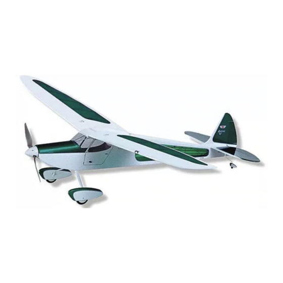
is pleased to offer you a new R/C version of this attractive design. Like the
original, the SIG R/C Rascal retains the classic lines of early postwar
private airplanes and has the great flying characteristics of a true
thoroughbred design.
Advertisement
Table of Contents

Related Manuals for SIG SIGRC80 Rascal C


Summary of Contents for SIG SIGRC80 Rascal C
- Page 1 Rascal design. Even though the little Rascal is long gone, SIG is pleased to offer you a new R/C version of this attractive design. Like the...
- Page 2 SIG's R/C Rascal has been designed to be powered by either geared Speed 400 electric motors or .049 -.07 glow engines. Either power source provides you with a great flying model that can be flown almost anywhere. The design is small enough to be flown in fairly confined areas such as a park, and large enough to turn in good thermaling capabilities.
- Page 3 Sheet Balsa 2 1/16"x3"x36" Balsa Sheet (Fuselage) Hardwood 1 3/16"x3/16"x3" Elevator Joiner 2 5/32" Dia. x1-1/4" Wing Dowels (Spruce) Shaped Balsa 2 24" Long Shaped Leading Edge 1 2" Long Shaped Wing Center 7 1/16"x1/4"x1" Tapered T.E. Section Block Stock (Shims) Hardware 8 2-56x3/8"...
-
Page 5: Pre-Construction Notes
But when building over the plans, be sure to protect them with waxed paper, the clear backing from covering film, etc. We built our R/C Rascals basically using SIG Thick CA glue. However, there are certain areas of construction that may require different adhesives. -
Page 6: Fuselage Construction
FUSELAGE CONSTRUCTION 1. The fuselage sides are made first. No matter how many times we say this, some builders always make the mistake of making either two right or two left fuselage sides! However, we'll say it again - MAKE ONE RIGHT AND ONE LEFT FUSELAGE SIDE. From your kit contents, locate the two laser cut 1/16"... - Page 7 Remove the fuselage sides from your building surface. Clamp or tape the sides together, matching the outlines of each exactly. Use your sanding block to sand their outer edges to exactly the same outline, giving you two identical fuselage sides. OPTIONAL: You will notice that our models have nice looking gray cabin interiors.
- Page 8 14. With the right fuselage side still flat on your work surface, test fit the left fuselage side in place onto the F-2 firewall, F-5, the servo tray and F-6. Each tab and slot should align easily and the structure should be square without misalignment. Remove the fuselage side and apply glue to the former and servo tray edges that will contact the fuselage side.
- Page 9 With the engine and mount still on the firewall, mark the location of the throttle tubing hole. This hole lines up with the hole in the engine s throttle arm and, in the case of the Norvel, is located on the far left side of the firewall. Remove the mount and engine from the firewall.
- Page 10 Glow Version: Use your hobby knife to clear out the bottom front sheeting, at the center front firewall location, to expose and match the half-circle drain hole in the bottom nose doubler. Use your Dremel Tool and a drum sanding bit to create the half-round shape in the front of the bottom sheeting, as shown on the plans.
- Page 11 26. As shown on the plans, the center section of the wing is integrated into the fuselage structure. In the following steps, the center section will be built to fit perfectly to the fuselage. Later, when building the wing panels, having the center already built will be very convenient.
- Page 12 31. Use 5-minute epoxy to now glue the 5/16" dia. piece of drilled dowel into the two holes at the rear of the center section. The hole in the dowel must line up with the hole in the 1/8" ply wing bolt plate in the fuselage. Remove the center section from the fuselage and use an 8-32 tap to thread the hole in the wing bolt plate (make sure to angle the tap to match the top curvature of the airfoiled center section).
- Page 13 Use 220 sandpaper to lightly sand the outer surface of both tubes. This allows them to be securely glued, using thick CA glue. As shown on the plans, the rear ends of the tubes exit the fuselage at severe angles. It is easiest to pre-cut these angles before installing the tubes - do this now.
-
Page 14: Wing Construction
WING CONSTRUCTION IMPORTANT NOTE: Refer to the KEY TO LASER-CUT BALSA PARTS to find the correct TOP and BOTTOM wing sheeting pieces. You will assemble two TOP and two BOTTOM wing sheets. It is important that you understand this. 40. Assemble both right and left top and bottom wing panel sheeting skins, including the center section sheets. Start by gluing the front and rear center section sheets together to make a single piece. - Page 15 Slip a few pieces of waxed paper between the shims and the wing panels to protect them from glue. Using a slower drying glue, such as SIG-BOND aliphatic resin, apply a thin bead of glue to the tops of each rib, ahead of the spar, to the rear edges of the ribs, where the sheeting will rest and to the top of the spar and to the top of the leading edge.
- Page 16 For maximum strength and working time, use a slower drying adhesive for joining the panels. Glues such as 30-minute epoxy or SIG-BOND aliphatic resin are perfect for the job. Be sure to wipe off any excess glue and tape the panels securely in place, allowing the glue to set.
-
Page 17: Tail Surfaces
Because CA glue is too quick for this step, we suggest a slower adhesive such as SIG-BOND. Apply glue to one side of one of the stabilizer cap sheets and position it in place against the S-1/S-2 core. Use pins or weights to keep this assembly flat against your work surface. - Page 18 58. The leading edges of the rudder and elevators are now sanded to shape to allow movement when hinged in place. As shown on the plans, these leading edges are double beveled to the centerline, allowing up and down and right and left movement.
- Page 19 62. With all parts now sanded, install the wing to the fuselage using the nylon bolt. Set the airplane on a flat surface and make sure the stabilizer will sit squarely in place in the top view as well as the front view. Glue the horizontal stabilizer in place at the rear of the fuselage, using slow drying glue.
- Page 20 67. Insert two #2-56 blind mounting nuts into the holes in the laser-cut plywood wheel pant mounts. Press the nuts firmly into the plywood until their heads contact the wood. Use a little thick CA glue around their edges to keep them in place. As shown, the blind nut/plywood assembly will be glued to the inside surface of the inner wheel pant half.
-
Page 21: Covering And Finishing
If needed, adjust the landing gear with pliers to get this kind of fit. Remove the landing gear and use 220 sandpaper to lightly sand the wire s vertical arms that fit between the supports in the fuselage. Use 5-minute epoxy to glue the landing gear in place, aligning it carefully. - Page 22 You can also use lite-ply to make the patterns for the vertical and horizontal tail group. Using such patterns ensures the trim scheme is uniform from side to side. After covering the glow engine version, we gave the firewall and the engine compartment a coat of epoxy resin. We brushed this resin a little over the trimmed edges of the covering, sealing them.
- Page 23 Wet-sand these parts with #600 sandpaper before painting. If you built the electric version of the R/C Rascal, you don't have to worry about fuel and can use just about any paint you like. For those of you who built the glow engine version, the paint you use must be fuel proof.
-
Page 24: Window Installation
Cockpit Braces As shown on the plans and in the photographs of our models, the forward cockpit, at the windshield, has two aluminum tube braces forming a V at the top of the instrument panel. The top ends of these tubes fit into the corners at the inside top of the cockpit wing fairing, against F-4. -
Page 25: Decal Application
The cleaner allows you to slide it exactly into position - don t press down on the decal. Once in position, use a paper towel to lightly dab the excess liquid away. Use a squeegee to set the decal in place (the SIG 4 Epoxy Spreader - SIGSH678 - is perfect for this job). - Page 26 Throughout our testing of the electric version of this model, we used both 7 and 8 cell battery packs, using Sanyo KR-600AE cells (1.2 volt, 600mAH). These battery packs have provided outstanding power and duration and we can highly recommend them. We honestly feel that if you re trying to save money, don't do it on batteries! We also used and highly recommend the AstroFlight Model 115D AC/DC Digital Peak Battery Charger.
-
Page 27: Control Linkages
Our Hitec 555 receiver was placed in a foam rectangle, cut to fit on the cabin floor. The antenna is routed out of the fuselage in the same manner as the electric version. The switch is mounted in the same location as the electric version. - Page 28 Use a small piece of aluminum foil over at the back of the fuselage, just behind the pushrod exit, to protect the fuselage from a possible stray drop of solder. Slip a brass tube connector onto the cable. As before, line-up the end of the connector wire with the end of the cable and slide the brass tube halfway onto the connector.
- Page 29 The real secret to this reliability is taking the time to bench run and completely break-in the engine, using the right propeller and the correct fuel. We broke our engines in using SIG 25% nitro 1/2A fuel (SIGCF016 in quarts). After break-in we switched to SIG 15% Nitro Airplane fuel.
-
Page 30: Flying Weight
SPECIFICATIONS: WING SPAN: WING AREA: 324 sq. in. LENGTH: 32-1/2 ELECTRIC: MAXX SPEED 400 MOTOR AND GEAR DRIVE UNIT POWER GLOW: .049 - .07 ENGINES GAS: 18.5 ounces* FLYING WEIGHT ELEC.: 23 ounces* CONTROLS Rudder, Elevator, and Throttle (*Note: These weights were obtained by building the actual kit and using the covering techniques, radio equipment and batteries specified in this manual. -
Page 31: Academy Of Model Aeronautics
Customer Service SIG MFG. CO. is totally committed to your success in both building and flying the RASCAL design. Should you encounter any problem building this kit, or discover any missing or damaged parts, please feel free to contact us by mail or telephone.
Need help?
Do you have a question about the SIGRC80 Rascal C and is the answer not in the manual?
Questions and answers