Table of Contents
Advertisement
Quick Links
Introduction
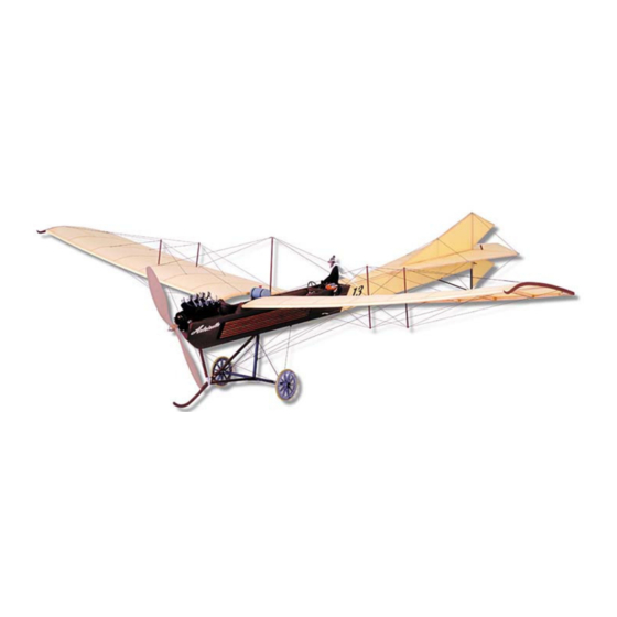
The Antoinette is considered by many as the most esthetically beautiful airplane of the early pioneering era of aviation. Designed
by Leon Levavasseur, a renowned boat builder and engineer, the Antoinette possessed many features and innovations that
were far ahead of its time.
The story begins in 1903 when Levavasseur, financed by a gentleman named Jules Gastambide, designed and built a super
light engine specifically for the new sport of motor boating. Named for Gastambide's daughter, Antoinette, the engine was a
large success and by 1904, it was powering winning powerboat racers all over Europe.
By 1906, in response to the rapidly growing interest in aviation, a new company was formed for the commercial development
and production of the Antoinette engine for use in aircraft. Gastambide was the president, Louis Bleriot vice-president, and
Levavasseur was the technical director. The Antoinette aircraft engine was innovative and relatively powerful. It employed direct
fuel injection and evaporative steam cooling.
Advertisement
Table of Contents

Related Manuals for SIG Antoinette 1909


Summary of Contents for SIG Antoinette 1909
- Page 1 Introduction The Antoinette is considered by many as the most esthetically beautiful airplane of the early pioneering era of aviation. Designed by Leon Levavasseur, a renowned boat builder and engineer, the Antoinette possessed many features and innovations that were far ahead of its time. The story begins in 1903 when Levavasseur, financed by a gentleman named Jules Gastambide, designed and built a super light engine specifically for the new sport of motor boating.
- Page 2 V-8, V-12, and even V-16 engines, were seemingly everywhere in competitions and record attempts. The SIG Antoinette is based on one of the more famous versions, the Model VII. The signature top and bottom rudders, triangular elevators, and boat prow fuselage are all faithfully incorporated into this unique piece of aviation history.
-
Page 3: Required Tools
Heat-Activated Covering Adhesive, .093" (3/32" or # 42) connectors available on the market. Be sure to such as SIG Stix-It or Solarfilm Balsaloc. .109" (7/64" or # 35) choose your connectors with weight, size, and A selection of hand tools, such as efficiency considerations in mind. - Page 4 1. Painting the front of the fuselage, the landing gear struts, and the wing tip skids brown to look like varnished wood. Do not use thick, heavy paints like epoxy or enamel on these large areas of the model. We prefer thinned SIG Supercoat Dope or "waterbased acrylic craft paint"...
-
Page 6: Fuselage Construction
FUSELAGE CONSTRUCTION 1. The basic framework of the fuselage will be built upside down on the plan. Pin the FUSELAGE TOP FRAME PLAN to your building board and cover with wax paper or plastic wrap for protection. Locate the plan on the building board so that former F1 is just past the end of the board (the top of F1 has two "tabs"... - Page 7 10a. Even though we’re not going to glue it on right now, let’s make the Tail Skid. Take one of the 10" pieces of bamboo provided and put a pencil mark at 7" and 8" from one end. The 1" area between these two marks needs to be bent to form the curved bottom of the tail skid, as shown on the plan.
-
Page 8: Landing Gear
15. Now repeat the previous step to glue 1/32" balsa sheeting onto the other side of the fuselage. Let dry. 16. Start pulling the front of both side sheets together at F1. You will have to start trimming some of the excess off both sheets so they don’t interfere with each other at the front. - Page 9 27. Notice that two of the WHL pieces will be laminated together to form the basic core of one wheel assembly. However before gluing them together, use a flat sanding block with medium grit sandpaper (100 to 200 grit), to bevel the outer edge of each WHL piece.
- Page 10 32. Complete the wheels by gluing a piece of surgical tubing around the outside to serve as the tire. Again, use thin CA and a fine applicator to keep the glue application under control. Start by tack gluing one end of the tubing in place in the groove with a single drop of glue.
- Page 11 b. Glue balsa parts LG3 and LG4 in place on each side of LG1. c. When dry, block sand all the edges of the skid assembly to clean up any rough spots. Note: Old photos show that the landing gear skids on the original Antoinettes were square cornered, not rounded or airfoil shaped as you might think they would be.
- Page 12 47. Glue in the balsa wing gussets WG1, WG2, WG3, and WG4 in the four corners of the wing panel. 48. Glue a 1/16"x1/4" balsa cap strip along the inside of the W1 wing rib. It should be flush with the top edge of the rib. 49.
-
Page 13: Tail Surfaces
53. After one set of wing mount tubes has been installed, repeat the same procedure to install the wing mount tubes for the opposite wing panel. 54. Glue the laser-cut plywood WM wing mounts in place over the front wing mount tubes. -
Page 14: Surface Preparation
You must first apply adhesive to the model structure where you want the covering to stick, using a heat-activated liquid adhesive such as SIG Stix-It or Solarfilm Balsaloc (not supplied). The following parts of the... -
Page 15: Final Assembly
CHG. Insert a laser-cut plywood control horn CHN into the slit, center the horn, and then, glue with Thin 63. A single SIG Easy Hinge, measuring 3/4"x1", is provided for hinging the rudder and elevator. Cut the Easy Hinge into 8 pieces that measure 1/8"x1/2". -
Page 16: Radio Installation
65. Repeat step 64 to hinge the elevator to the back of the stabilizer. 66. The 1/32" laser-cut plywood WTS wing tip skids provided in the kit are a decorative scale part. They are not structural or meant to be functional. You can leave them off if you want to without affecting the airplane in any way other than visually. We like them and feel that they add to the "Victorian Age"... - Page 17 71. Pull-pull control lines are used to connect the rudder servo to the rudder control horn. A 10 foot long piece of monofilament fishing line is provided for this. Cut it in half into two 5 foot long pieces, one for the rudder and one to use later for the elevator.
-
Page 18: Control Movements
Battery Velcro® is supplied to mount your battery pack to the balsa BTM battery mount located in front of former F3. The second BTM in back of F3 is for other possible battery configurations. We’ve never had to use it yet, but recommend that you leave it in the airplane for structural strength. - Page 19 Tip: Put the bottom mounting screw in first! The big gear on the front of the motor partly blocks access to the bottom mounting screw. So while you still have the motor assembly in your hands, put a screw through the bottom hole of the plywood motor mount, angling it past the gear.
- Page 20 When dry, reinforce the seams by applying a little Thick CA glue on the inside of the cylinders. Let dry. 84d. Carefully drag the bottom of the cylinder bank against a fine sanding block (150 grit or finer) to even out the edges. Don’t try to sand too fast or too hard. You’ll crush the thin plastic.
- Page 21 GWS propellers are excellent products but they are molded in bright orange plastic! To make ours more realistic, we painted them. First, balance the prop with a prop balancer. If needed, sand the backside of the heavier blade to bring the prop into balance.
- Page 22 90a. Start by cutting 1/16" sq. balsa sticks for the radiator Frame and Crosspieces. Glue them together over the plan. b. Cut pieces of 3/16" sq. balsa stick for the Ends. Glue in place on both ends of the frame. c.
- Page 23 For reference, we've included a 3-view "Rigging Diagram" of the Antoinette at the end of these instructions. This drawing shows and identifies the rigging locations we put on our factory-built Antoinette models. The "rigging wires" are actually black elastic thread, and an 8 yard long piece is included in this kit to make all of the rigging you see in the diagram. You will also need the remaining 1/16"od x1/4"...
- Page 24 c. Glue the other end of the elastic thread to the side of wing rib W3 opposite the aluminum tube rigging point B. The easiest way is to first put a small drop of Thin CA on the rib, then place the end of the thread in the glue and set it with CA Accelerator.
- Page 25 d. Remove the monofilament line and use small needle nose pliers to crush the middle of the swage tube, locking the thread loop in place. Trim off the short length of excess thread. This end of the rigging wire is done. e.
- Page 26 110a Drill .046" dia. holes (3/64" or #56 bit) through the top of the Fin at points R and T. Center the holes in the 1/8" balsa stick. b. Drill .046" dia. holes through the edges of the Stabilizer at points V and W. Center the holes in the 1/8”...
- Page 27 Want to learn more? During our research of the Antoinette and the other SIG Pioneers Of Flight models, we had a lot of fun reading related books for scraps of information and to find the occasional grainy black and white photograph of our subjects.
-
Page 28: Customer Service
Customer Service SIG MFG. CO., INC. is totally committed to your success in both assembling and flying the 1909 ANTOINETTE kit. Should you encounter any problem building this kit or discover any missing or damaged parts, please feel free to contact us by mail or telephone. - Page 29 Warning! This is not a toy! Flying machines of any form, either model-size or full-size, are not toys! Because of the speeds that airplanes must achieve in order to fly, they are capable of causing serious bodily harm and property damage if they crash. IT IS YOUR RESPONSIBILITY AND YOURS ALONE to assemble this model airplane correctly according to the plans and instructions, to ground test the finished model before each flight to make sure it is completely airworthy, and to always fly your model in a safe location and in a safe manner.
- Page 30 LIMIT OF LIABILITY: The craftsmanship, attention to detail and actions of the builder/flyer of this model airplane kit will ultimately determine the airworthiness, flight performance and safety of the finished model. SIG MFG. CO's obligation shall be to replace those parts of the kit proven to be defective or missing. The user shall determine the suitability of the product for his or...
Need help?
Do you have a question about the Antoinette 1909 and is the answer not in the manual?
Questions and answers