Table of Contents
Advertisement
Quick Links
The Clipped Wing Cub Story
The classic Piper J-3 Cub has been America's favorite light plane for over 40 years. More than 20,000 of them were built between
1937 and 1947 for both civilian and military use. By 1980, the number of still airworthy J-3's in the U.S. had declined to
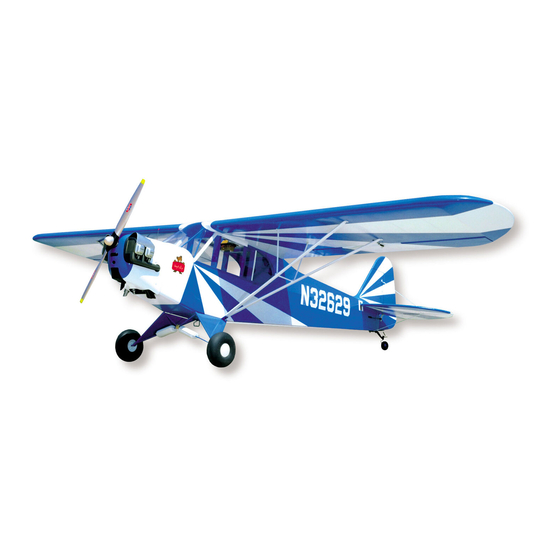
approximately 3,600. One of these bears registration N32629 and is recognized worldwide as Hazel Sig's Clipped Wing Cub.
N32629 was manufactured in 1941 at the Piper factory in Lock Haven, Pennsylvania as a standard Piper J-3C-65 Cub, serial
number 5498. Not much is known about the first 12 years of its life. The first logged entry was made on February 12, 1953 by a
flier in Frederick, Oklahoma. He said; "The previous owner did not comply with CAR. 43·22 on the maintenance of aircraft
records. The aircraft log, if maintained, has been lost or destroyed. From known information, the aircraft has been estimated to
have approximately 4000 hours total time". With that many hours of flight time accumulated in just 12 years, it's pretty safe to
assume that N32629 was used for flight training during the 1940's. The Cub was sold in 1955 to an A & E mechanic who moved it
to Mount Pleasant, Iowa. It remained in Iowa through the 1960's, being used by several different owners for pleasure flying.
Hazel Sig, president of SIG MFG. CO.,
purchased N32629 in January of 1968. She
flew the J-3 in its standard form through the
spring and summer of that year. The log books
showed that the Cub had been covered with
ceconite and painted with enamel in 1965, just
three years before Hazel bought it. The
ceconite and enamel turned out to be a bad
combination. After the simplest aerobatics, the
enamel had begun to crack and loosen from the
fabric in several places. It was soon obvious
that the Cub was going to need recovering
again in the near future, much sooner than
should have been the case.
Hazel Sig standing beside her newly acquired standard Piper J-3 Cub at Sig
Field Montezuma, January 1968. At that time, N32629 was painted cub yellow
with red trim and black registration numbers. It was manufactured in 1941.
Advertisement
Table of Contents

Related Manuals for SIG Sigrc47


Summary of Contents for SIG Sigrc47
- Page 1 1937 and 1947 for both civilian and military use. By 1980, the number of still airworthy J-3's in the U.S. had declined to approximately 3,600. One of these bears registration N32629 and is recognized worldwide as Hazel Sig's Clipped Wing Cub.
- Page 2 "Maxey is the one who actually loaded the spray gun". Hazel Sig taxies her rebuilt Clipped Wing Cub out of the hangar for its very first The almost-done Cub took another truck ride test flight at the Ottumwa Airport in the summer of 1969. Approximately 3-112...
- Page 3 2-Stroke or 4-Stroke? The first choice you must make in selecting an engine for your Cub is to decide whether you want to use a 2-stroke or 4-stroke motor. From the reports that we have received from our customers, 4-stroke engines have proven to be much more popular for the Cub than 2-strokes.
- Page 4 Sig-Bond (alphatic resin type) glue works best for the majority of the general framework construction. Areas subjected to unusual strain, or including metal pieces, should be epoxied with Sig Epoxy Glue (slow drying) or Sig Kwik-Set (5-minute) Epoxy Glue. You will also find that the cyanoacrylate type adhesives (Hot Stuff, Jet, etc.) can be extremely quick and handy for some applications.
-
Page 5: Fuselage Construction
FUSELAGE CONSTRUCTION 1. Building The Fuselage Formers Due to their large size, some of the fuselage formers could not be furnished in one-piece, but need to be built up from several pieces. Take great care in the next few steps to insure that these formers are built accurately. How well you make them match the plan will determine how well other fuselage parts will fit together later a. - Page 6 Epoxy formers F5, F6 and F7 to the Right Fuselage Side and Cabin Top piece. Glue them on one at a time with 5-minute epoxy. Use a triangle to get them on square. g. Epoxy the Left Cabin Top piece in place along the top of the formers. When dry, measure at each former from the bottom of the Right Cabin Top to the top edge of the Right Fuse Side.
-
Page 7: Nose Assembly
3. Nose Assembly a. Epoxy the die-cut plywood firewall parts F1A, F1B and F1C together. Make certain that F1C is centered on the back. Carefully mark the vertical centerline and the thrust line on the front of the firewall assembly. Position your engine mount on the front of the firewall, drill holes for mounting, and install blind nuts. - Page 8 Glue in place balsa formers F2, F3 and Steerable Tailwheel Unit Assembly F4, and the 1/4" square balsa stringer that goes between them. Check the 1. Temporarily bolt the two formed exact locations of the formers carefully. metal Leaf Springs together using When dry, lightly touch up the edges of the 6-32x1/2"...
- Page 9 Cut and glue in place the 5/16" sq. balsa front Windshield Braces. They should also be glued in flush with the lite-ply Sides and spruce Cabin Tops. You'll have to hollow out the bottom inside corner of the Windshield Braces slightly so that they will clear the Cabin Wires.
- Page 10 Refer to section "Sanding and Painting Plastic Parts", in section 20. Cut a piece of Sig Regular Weight Glass Cloth (SIGGF001, not supplied) that will cover approximately half of the inside of the cowl.
- Page 11 Scrape the seam on the outside of the cowl to take out any rough spots or flaws. Low spots in the seam can be filled with Sig Epoxolite putty. Don't put on too much Epoxolite and expect to sand away the excess later. Epoxolite dries very hard and must be worked into its final desired shape before it hardens.
-
Page 12: Main Landing Gear
Make any small openings or other provisions where necessary to allow access to the needle valve and for hooking up the glow plug. 7. Main Landing Gear Assembly of the main gear requires the completed fuselage. Place the 3/16" Main Gear wire and the 3/16" Rear Brace wire into the grooved L.G. Blocks in the bottom of the fuselage. Note on the plan that the Main Gear wire should be perpendicular to the bottom of the fuselage while the Rear Brace wire should be angled forward to meet it near the axle. -
Page 13: Fin And Rudder
For maximum strength, we recommend that you completely cover the balsa fairings with regular weight fiberglass cloth and slow-drying epoxy glue (applying it like you did on the inside of the cowl). Lap the cloth past the edges of the wood, completely around the 3/16"... - Page 14 Add R3 and R4 printed pieces. Shape and install the 3/8"x5/8" balsa Rudder Bottom. Cut to length and glue in all 1/4"x3/8" balsa ribs. Add RG-1, RG-2, and the 1/8"x1/4" balsa brace. When dry, unpin from the plan and sand the outside edges round. Inlet the bottom of the Rudder to accept the rudder horn.
-
Page 15: Wing Construction
WING CONSTRUCTION IMPORTANT NOTE: The wing is basically constructed in three separate sections - a flat Center Section, a Right Wing Panel, and a Left Wing Panel. First you must construct the separate Right and Left Wing Panels by following all the instructions up the "Center Section"... - Page 16 Pin wing panel back in place on the plan, at the same time gluing it to the Bottom Trailing Edge and Aileron Sheeting. Add small riblet W3A. Be careful about exact location. Extend a line off of the die-cut slit in ribs W4 and W5 for alignment. Add die-cut plywood riblet W5A and balsa riblets W4A and W4B.
-
Page 17: Center Section
Study the Wingtip Alignment Drawing carefully in preparation for gluing the Tip Plate onto the end of the wing panel. Proper positioning of it against the W4 end rib is important for correct assembly of the rest of the wingtip parts in subsequent steps. - Page 18 b. Cut to length a 1/4"x3/8" balsa stick and glue it onto the front edge of the bottom sheeting. Pin all the 1/4" sq. balsa bottom spars, the two center WA ribs, and the WSP pieces in place. After you get these parts squared up with each other, glue all the joints.
- Page 19 m. Carve and sand the trailing edges round. Carefully block sand the entire wing until all joints are smooth and even. Use as large a block as possible to avoid sanding down anyone area too much. 13. Cutting Out The Ailerons a.
-
Page 20: Wing Struts
b. Set the wing on the fuselage, sliding it forward as far as possible. Mark and drill a 5/32"x5/16" hole in the wing's Front Dihedral Brace for the Cabin Wires to go through. The wing should then slide all the way forward with the trailing edge dropping down in front of the T.E Crosspiece. - Page 21 (NOTE: At this point, there is no "right" or "left" difference between the two wing strut assemblies, as is called for on the plan.) Four pieces of 1/16"x1/2"x2-1/4" aluminum are provided for making the Upper Strut Fittings. Drill, shape, and bend these pieces as shown on the plan to make two #1 and two #2 Upper Strut Fittings.
-
Page 22: Radio Installation
Make a final assembly of all the strut pieces to the model. During the assembly epoxy the flat head bolts into the spruce struts; epoxy together the lower ends of the Jury Struts where they overlap; and epoxy on the 4-40 hex nuts that hold them all together. - Page 23 A long nylon control horn is supplied for the elevator. Install it on the bottom of the left elevator with #2x3/4" sheet metal screws. Once installed, cut off the excess ends of the screws flush with the top of the nylon retainer plate. Pushrod Assembly Materials are supplied for building fiberglass pushrods to link the elevator...
- Page 24 Receiver The receiver should also be wrapped in foam rubber and stowed as far forward as possible. Make certain that it is somehow fastened in place so it will not move around during flight. A 36" long piece of large (3/16" o.d. approx.) nylon tubing is provided for making an internal antenna mount.
- Page 25 The clunk line on the fuel feed tube must swing freely without hitting the back of the tank. (If your tank, as supplied, does not come with silicone tubing for the internal fuel feed line, substitute a piece of Sig Heat-Proof Silicone Tubing, SIGSH290 Large.
- Page 26 19. Covering And Painting The Framework The completed Cub framework can be Hints On Covering The Fin Fillet covered with Sig Koverall, Sig Silk or an iron-on type of covering material (either On the full-size Piper Cubs, the plastic or fabric). Whatever type of...
- Page 27 The cowling, dummy engine, and bungee covers are molded out of ABS plastic. We recommend that they be painted with Sig Supercoat Dope for a good color match to the rest of the doped model. Hobbypoxy, K & B Superpoxy, and Dulux Enamel have also been proven compatible with the plastic.
- Page 28 Start by wetting the surface of the model where the decal will be placed with a generous quantity of soapy water solution (a little dish soap in water, or a commercial cleaner like Sig Blue Magic Model Airplane Cleaner, "409", or "Fantastic" brand cleaners will all work equally well).
- Page 29 Screw one threaded link and jam nut onto the threaded end of each rod. Solder one of the unthreaded links to the other end of each. Drill #44 holes through the stab and fin trailing edges at the brace wire attachment points drawn on the plans. Fit the wires to the model.
- Page 30 Be certain to carefully range check your radio equipment and see how it operates with the engine running before attempting test flights. A lot of problems can be avoided if the engine has been well broken in and the idle adjustment perfected on a test block or in another airplane before installation in the new model.
- Page 33 LIMIT OF LIABILITY: In use of our products, Sig Mfg. Co.'s only obligation shall be to replace such quantity of the product proven to be defective. User shall determine the suitability of the product for his or her intended use and shall assume all risk and liability in connection...
Need help?
Do you have a question about the Sigrc47 and is the answer not in the manual?
Questions and answers