Advertisement
Quick Links
Sig Mfg. Co., Inc....401-7 South Front Street....Montezuma, Iowa 50171
Introduction
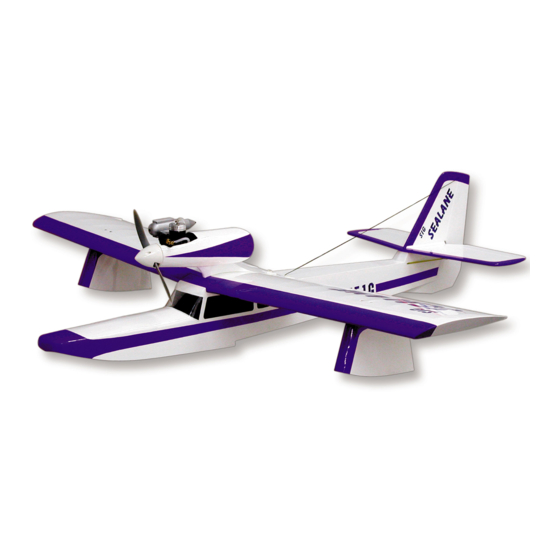
The SEALANE takes off and lands on water just as easy as the Sig Kadet LT40 does on solid ground. Gentle, graceful, sure
footed. However, once the bond has been broken between plane and pond, the SEALANE roars to life with a performance not to
be missed. Loops, rolls, inverted flight; all at your fingertips. Water handling characteristics are very positive, even in cross
winds. It's the perfect choice for your first seaplane adventure. And although the SEALANE is no landlubber, there is an optional
fixed landing gear design for adventures off water down at the local field.
This assembly manual has been specifically sequenced to get your SEALANE assembled and into the air very quickly. We
strongly suggest that you read through the manual first to get familiar with the various parts and their assembly sequences. The
proper assembly and flying of this aircraft is your responsibility. If you are new to the sport/hobby of radio control, we urge you to
seek the assistance of a qualified person to help you assemble this model airplane. If you do not understand a particular
assembly step or sequence, do not guess - find qualified help and use it.
Radio Equipment
The SEALANE requires a standard 4-channel radio system and four standard servos. We have used and can highly recommend
both the Hitec™ and Airtronics™ systems. Both of these very affordable and reliable radio systems offer all the features you'll
need for this and the many other R/C aircraft in your future. For reference, this assembly manual shows the installation of a
Hitec™ radio system with standard servos. The standard 6" aileron servo extension that comes with the radio system will be
used but you will not need any additional radio accessories.
Advertisement

Related Manuals for SIG Sealane


Summary of Contents for SIG Sealane
- Page 1 Introduction The SEALANE takes off and lands on water just as easy as the Sig Kadet LT40 does on solid ground. Gentle, graceful, sure footed. However, once the bond has been broken between plane and pond, the SEALANE roars to life with a performance not to be missed.
- Page 2 Covering Material And Waterproofing Your SEALANE has been designed to be completely covered with any of the popular plastic iron on covering materials on the market. These covering materials are waterproof and by carefully overlapping the seams approximately 3/32", your SEALANE will be almost waterproof.
- Page 3 Pushrod End - @ 2-56 pushrod 1-1/2” long Tail Surfaces Elevator Joiner Bent 3/32” Music Wire Servos Tail Surfaces Nylon Control Sig Medium Control Horns - 1 Tail Surfaces Control Horns #2 x1/2” Sheet Metal Screw. Horns Left & 1 Right Screws Wing Wing Attach Bolts 1/4-20 x1-1/2”...
- Page 4 Optional Landing Gear Parts (Not included in Kit) Continued Qty Assembly Name Size & Material Qty Assembly Name Size & Material Main Landing Gear Wheel Collars 3/16" Wheel Collars Main Landing Gear Mounting 1/8" Lite Plywood Main Landing Gear Copper Wire .016 Soft Copper Wire Main Landing Gear Main Landing Gear Legs 3/16"x12"...
-
Page 6: Building The Tail Surfaces
General Building Notes 1. The SEALANE is recommended for the modeler who has previous building experience. Although the SEALANE is an easy model to build and fly, the instructions were written assuming that the builder has previous experience. As such, procedures such as how to make a proper wood joint or detailed covering instructions are not covered. - Page 7 7. Glue the fuselage doublers (F-2) to the inside of the fuselage sides (F-1). Be sure that you make a left and a right side. 8. Glue formers F-3 and F-5 into position on the right fuselage side. Use a small square to make sure that the formers are 90° to the fuselage side.
- Page 8 When the sheet is positioned properly you can glue it to the fuselage. When the glue is dry, thoroughly wet the outside of the sheet with an ammonia based cleaner such as Sig’s Pure Magic Airplane Cleaner. Allow it to soak in for about 10 minutes.
- Page 9 23. Working rearward from F-4 toward F-10, glue the bottom sheet pieces into position. The inboard edge should be centered on the keel (F-14) and the outboard edge should extend past the fuselage side. Glue the 1/4"x2-1/2"x6" balsa sheet to the bottom of the fuselage behind F-10.
-
Page 10: Building The Wing
BUILDING THE WING NOTE: The wing is built directly on the plan, so cover the plan with wax paper before assembly. These instructions are identical for both the right and left wing panels. 27. Start building the right wing by pinning the lower 1/4" sq. spruce spar to the plan. Also, pin the 1/4"... - Page 11 39. Roll the sheeting back and down onto the wing ribs. Glue the sheet to all of the wing ribs and to the top spruce spar. Note: You can moisten the outside face of this sheet with an ammonia based cleaner such as Sig’s Pure Magic Airplane Cleaner.
- Page 12 44. Roll the sheeting back and down onto the wing ribs. Glue the sheet to all of the wing ribs and to the top spruce spar. Note: You can moisten the outside face of this sheet with an ammonia based cleaner such as Sig’s Pure Magic Airplane Cleaner.
- Page 13 51. Use epoxy to glue W-10 to the face of W-1. The bottom should be flush with the bottom of the wing and the front should be flush with the front of W-6. Be sure that the pointed part is not blocking the hole between the spars. 52.
- Page 14 59. Hold the wing securely in position on the fuselage and drill 3/16" holes through the wing and into the wing bolt blocks in the fuselage. The drill should be held so that it is angled 90° to the top of the wing surface. Remove the wing from the model.
- Page 15 BUILDING THE MOTOR PYLON 66. Place the motor mount that you are using on the firewall (P-2). Center the hole in the mount with the hole in P-2. Mark and drill the mounting holes in P-2. Remove the mount from the firewall and install the 6-32 blind nuts. Install the mount on the firewall with the proper screws.
- Page 16 70. Mark the firewall for the location of the throttle pushrod. Mark the bottom of the pod where the throttle cable will exit. Now carefully drill holes in these parts making sure that you do not damage the fuel tank.Insert the throttle pushrod housing into the pod with about 2"...
- Page 17 Remove the motor mount from the firewall. The firewall and exposed wood inside the fairing should be painted and sealed with a fuel proof paint such as Sig Butyrate Dope or epoxy. Test fit the motor pylon assembly to the wing. The supports should be a tight fit into the slot in the wing. Drill a 1/16" hole through the wing to allow the throttle pushrod housing to pass through.
- Page 18 81. Glue the parts T-2, T-3 and T-4 to T-1 as shown. They should be 90° to T-1. When the glue is dry, sand the front of the assembly so the front of the formers are flush with T-1. 82. Test fit and glue the 1/4” balsa tip float leading edge into position.
- Page 19 88. Using the locations marked on F-1C, drill two 3/16" holes through each fuselage side. Fit and glue the front and rear landing gear support into position as shown on the plan. The top edges should line up with the bottom of the holes in the fuselage sides.
- Page 20 Mount the elevator and rudder servos into the servo tray using the hardware provided with the radio. Mount the switch for the radio into the servo tray. Unless the switch is extra long, you will not use the normal face plate provided with the switch.
-
Page 21: Covering Your Model
The bare wood can be painted (we used Sig Black Dope) if you would like. Glue the windshield to the fuselage. When the glue is dry, finish the edges of the windshield with trim tape as shown. - Page 22 103. Assemble the rear ends of the elevator and rudder pushrods, using the 2-56 x7" threaded one-end pushrods. Insert the unthreaded end all the way into nylon tube and thread the pushrod in place, using about 1/2 of the threads. Now thread the nylon clevis onto the reaming pushrod threads.
- Page 23 111. Thread the nylon torque rod fittings onto the aileron pushrods. Attach them to the connectors on the aileron torque rods. With the ailerons in the neutral position and the servo centered, mark, cut, and solder the metal clevisie to the front end of the pushrods.
- Page 24 117. Install the propeller and spinner onto the motor. Install the muffler onto the motor and connect the feed and vent lines. NOTE: The pylon feature found on flying boats such as the Sealane are more sensitive to vibration than a traditional fuselage mounted motor. For this reason it is important that you balance the propeller / spinner assembly to minimize vibration.
- Page 25 In the air, the SeaLane flys like any other model. Gain a little altitude and get the feel of the model. Once at altitude, trim as required to maintain straight and level flight. Reduce the throttle at altitude and see how it handles at slow speed.
- Page 26 Customer Service SIG MFG. CO. is totally committed to your success in both building and flying the SEALANE design. Should you encounter any problem building this kit, or discover any missing or damaged parts, please feel free to contact us by mail or telephone.
Need help?
Do you have a question about the Sealane and is the answer not in the manual?
Questions and answers