SIG PIPER J-3 CUB Building And Flying Instructions
Hide thumbs
Also See for PIPER J-3 CUB:
- Building and flying instructions (16 pages) ,
- Assembly instructions manual (6 pages) ,
- Assembly instructions/use and care manual (9 pages)
Table of Contents
Advertisement
Sig Mfg. Co., Inc....401-7 South Front Street....Montezuma, Iowa 50171
Introduction
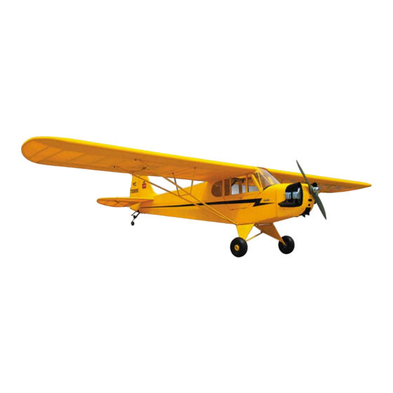
Congratulations on your purchase of the 1/5-scale SIG PIPER J-3 CUB kit. This is a computer engineered laser-cut kit of
America's favorite lightplane. Laser cutting is more expensive than the older methods of kit production, but it provides incredible
accuracy and perfect parts fit. We believe that you will enjoy putting this kit together just as much as you'll enjoy its legendary
flying characteristics.
Advertisement
Table of Contents

Related Manuals for SIG PIPER J-3 CUB


Summary of Contents for SIG PIPER J-3 CUB
- Page 1 Introduction Congratulations on your purchase of the 1/5-scale SIG PIPER J-3 CUB kit. This is a computer engineered laser-cut kit of America’s favorite lightplane. Laser cutting is more expensive than the older methods of kit production, but it provides incredible accuracy and perfect parts fit.
- Page 2 The Piper J-3 Cub Story The yellow Piper J-3 Cub is one of aviation's genuine classics. In the decades right before and after World War II, the Piper Cub was the most commonly seen lightplane at airports all over the country. It's been said that back then most people thought that every airplane flying was either a DC-3 or a Piper Cub.
-
Page 3: Engine Selection
In the spring of 1969, the Cub was trucked back to Ottumwa airport for final assembly. Hazel made the first test flight herself and then flew the Cub back to it’s home at SIG FIELD. Pilots who’ve had a chance at the controls of Hazel’s Clipped Wing say it is the sweetest flying Cub they’ve ever flown. -
Page 4: Radio Equipment
Power Drill With Selection of Bits Soldering Iron, Solder and Soldering Paste Flux A selection of glues - SIG Thin and Thick CA and SIG Kwik-Set 5-Minute Epoxy Clear Dope For Fuel-Proofing Engine Compartment Threadlock Compound, Such as Loctite® Non-Permanent Blue Dremel®... - Page 5 The following is a complete list of all parts contained in this kit. Before beginning assembly, we suggest that you take the time to inventory the parts in your kit. COMPLETE KIT PARTS LIST Laser-Cut Balsa Sheets 1 3/32" thick Sheet #3: W-2 3 3/32"...
- Page 6 4 1/4" od Nylon Retainers: pushrod connectors(2), door latch(2) Easy Hinge Bag 17 3/4"x1" SIG Easy Hinges Nylon Hinge Bag 2 Molded Nylon Hinges 4 Straight Pins Rudder Pull-Pull Bag 1 .021" dia.x6 ft. Steel Cable 4 3/32"...
-
Page 11: Fuselage Construction
FUSELAGE CONSTRUCTION Fuselage Sub-Assemblies 1a. Mark the vertical centerline and thrust line on the F-1 firewall using the plan cross-section and tick marks on the firewall. b. Check the width of your engine and determine the spacing needed between the motor mounts. Using the lines on the firewall, locate the mounts and mark the location of the four mounting holes on the firewall. - Page 12 c. Epoxy the square nuts firmly in place being careful not to get any glue on the machine screws. When dry, remove the leafspring. Locate former F-5A (sheet 10) and former F-6A (sheet 23). Using the cross-sections on the plans as a guide, glue the 1/8"x1/4"...
- Page 13 b. Assemble fuselage formers F-1, F-3, F-4, F-5, F-6, F-7, the Servo Tray, and Tank Floor in place between the fuselage sides. Add the Fuselage Top Rear, Fuselage Bottom Rear, Cabin Floor Rear, Cabin Floor Front, Nose Top, and Stab Mount between the fuselage sides.
- Page 14 c. Put in the remaining 3/16" sq. and 1/4" sq. pieces in their respective notches. Also, cut two 5" long pieces of 1/8"x1/4" balsa, and insert them in the upper and lower notches in the rear of the ribs. Also, install the Hatch Mounts (sheet 26). d.
- Page 15 Removable Cabin Hatch The top portion of the fuselage cabin sheeting (the area between the 3/16" sq. and 1/4" sq. balsa pieces that were installed in step 17b.) will be removable so that you will have easy top access to the wing mounting hardware. 24.
- Page 16 30a. Glue the two hardwood Landing Gear Blocks into the bottom of the fuselage. b. Cut 2 pieces of 1/2" balsa triangle stock to 4-11/16" long. Glue them in place in the fuselage at the front and rear of the front Landing Gear Block, to reinforce it to the bottom of the fuselage.
- Page 17 Piper J-3 Cub. Cut the dowels to length, bevel the ends to fit, and then glue them in place. Refer to the front view plan.
- Page 18 44. Screw the threaded end of the wire into the nylon tube from the outside of the door. Screw it in until the threaded portion goes completely thru the tube and the soldered washer is up against the outside of the door. Now place another #2 flat metal washer on the opposite side of the door and screw on a 2-56 hex nut.
-
Page 19: Stabilizer And Elevator
Stabilizer And Elevator 60a. Tape or pin the stabilizer/elevator plan down on a flat building board. Cover with wax paper or plastic wrap. Locate parts S-1, S-4, S-5, S-6 (sheet 13), and parts S- 2, S-3 (sheet 14). Glue and pin these parts together over the plan. b. -
Page 20: Fin And Rudder
d. Trial fit the elevators together on the wire joiner. Adjust the grooves and holes as required to achieve a good fit. Then, mix up a small batch of 5-minute epoxy and apply glue into both holes and the grooves in elevator halves. Install the Joiner Wire into each elevator half and wipe off any excess epoxy. -
Page 21: Wing Construction
WING CONSTRUCTION As mentioned in the introduction, you can build either a standard PIPER J-3 CUB (84-1/2" wingspan) or a CLIPPED WING CUB (68-1/4" wingspan) from this kit. All of the parts to build either version are included. The differences between the J-3 and the CLIPPED WING are the wing panel length, the wing strut length, and the jury strut patterns. - Page 22 Proceed down the length of the wing panel, pinning the parts to the spars. You may notice as you are going along that some of the ribs may not line up exactly with the plan. This is because the plan paper can shrink or expand a little bit in size with climate changes.
- Page 23 2) When dry, apply glue along the ribs and the front half of the top spar. Uniformly press the sheet down onto the ribs and spar. Use a straightedge and weight to hold the sheet flat to the spar and spray with accelerator. Builder’s Tip: You may need to wet the outside surface of the sheet slightly to make it bend over the ribs easier.
- Page 24 87. Cut to length and glue on the bottom 3/32"x3/4"x21-1/4" balsa sheet for the rear edge of the aileron bay (remember step 79). When dry, use a sanding block sand the top and bottom sheets even with the 1/8"x1/4" wing spars. 88.
- Page 25 Locate the 1/2"x1"x2" balsa Wing Tip Block and glue into place at the front of the wingtip. Sheet the front of the wingtip, top, and bottom with 3/32"x3" balsa sheet. 100. Glue 3/32"x1/4" balsa capstrips to the top and bottom of rib W-6. 101.
-
Page 26: Aileron Servo Installation
c. Glue seven balsa Aileron Ribs (sheet 11) in place, locating them in the slots in the Aileron Bottom Sheet. d. Locate the plywood Aileron Horn Mount (sheet 27). Notice the small hole in the part. This is where the nylon control horn will be screwed on later. In order to make that installation of the control horn easier later on, it’s a good idea to pre- thread the hole now by screwing in a #2 x3/8"... -
Page 27: Wing Struts
Wing Struts The Front Wing Struts for the Piper J-3 Cub are 1/4"x1/2"x24-1/4" spruce, and the Rear Wing Struts are 1/4"x3/8"x24-1/4" spruce. Study the J-3 Wing Strut Plan (plan sheet 3) to understand the design of the wing struts. Notice that the Front and Rear Struts will be joined permanently together into a one-piece "V"-shaped wing strut assembly. - Page 28 b. Round the two outside corners of the fittings with a file or grinder. c. Lay the Fuselage Strut Fitting back over the plan pattern and mark the bend line exactly where shown. Clamp the part in a vise right at the line, and gently bend it to the angle shown. 119.
-
Page 29: Main Landing Gear
e. When satisfied with the fit, take the Upper Strut Fittings off one at a time, apply epoxy, slip the fitting back into the slot, bolt it back in place, wipe off any excess glue, and then let dry. 125. When dry, remove the strut assemblies from the airplane. Carve and sand the spruce Wing Struts to finished shape. 126. - Page 30 b. The wires are held in the grooved blocks with the four Nylon Landing Gear Straps provided. The straps should be installed all the way to the ends of the grooved blocks, right up against the wire where it exits the block. This is done to insure the landing gear cannot shift sideways in a rough landing.
- Page 31 Continue this process until you have glued both sides of all the hinges. CAUTION: SIG Easy Hinges are designed to be used with any THIN CA adhesive. Make sure you are using the thinnest variety. Do not use medium or thick CA, or any other type of glue, on Easy Hinges. Also, never use CA accelerator on Easy Hinges.
-
Page 32: Covering And Finishing
Fuel Proofing Before covering the fuselage, coat the entire front surface of the firewall with two or three coats of SIG Clear Dope, polyester or epoxy resin, and other fuel proof paint. Also, fuel proof the grooves on the main gear blocks and around the door opening. -
Page 33: Attaching The Rudder
155. After the rudder is covered, epoxy the molded Nylon Rudder Horn at the bottom. Let dry. 156. Hinge the rudder to the back of the fuselage with three SIG Easy Hinges, following the same procedures you used to hinge the elevators to the stabilizer earlier. - Page 34 Then, we sprayed two coats of SIG CUB YELLOW SUPERCOAT DOPE over the primer. The SIG CUB YELLOW DOPE is a pretty good color match to the SOLARTEX CUB YELLOW FABRIC covering that we used.
- Page 35 b. Glue the dummy engines to the sides of the cowling. Study the photos and plans carefully to get the location exactly right. 162. Cut out the right and left molded plastic dummy engine shrouds. The cut lines are molded right into the parts. Trial fit the shrouds onto the cowl to fine tune the fit of the trimmed edges.
- Page 36 All that’s left is to hinge the ailerons to the wing and make the aileron pushrods. 174. Use four SIG Easy Hinges to hinge each aileron its wing panel. Use the same procedures you did in the section "Attaching The Tail Surfaces" earlier. The aileron hinges should be installed in the 3/32"...
- Page 37 179. Slide the unfinished end of the pushrod through the Elevator Pushrod Sleeve that is already in the fuselage. Slide it in from the servo end. Slide it in until you can hook the Solder Link in the elevator servo arm. 180.
-
Page 38: Radio Check
Receiver And Battery Pack The single heaviest unit of the radio system is the of course battery pack. This means that you can, if needed, locate the batteries wherever they are required in the airplane to help achieve the correct balance point. Be sure to wrap the battery pack and the receiver in foam rubber and use rubber bands or tie-wraps to secure to the model structure so that it can’t move around in flight. -
Page 39: Throttle Pushrod
195. Insert the top of the Formed Tailwheel Wire through the Nylon Tailwheel Bearing and secure in place with the Steering Arm. File or grind a flat spot on the wire where the set screw will make contact. 196. The two tailwheel Steering Springs can now be installed, connecting the tailwheel Steering Arm to the Rudder Horn. Use needle nose pliers to make a loop in one end of the spring to hook into the outermost hole on the back edge of the rudder horn. -
Page 40: Instrument Panel
After setting overnight, the decal will be solidly adhered to the surface. Instrument Panel A full-color printed paper Piper J-3 Cub instrument panel is included in this kit. Simply cut it out with a sharp scissors and use spray cement to glue it in place. - Page 41 In the air, you’ll find the Cub stable, yet responsive. With practice, it is capable of doing basic maneuvers such as inside loops, barrel rolls, and spins. After you’ve had a chance to get the model all trimmed out, practice making your turns by coordinating rudder commands in with the ailerons, as is done in a full size airplane.
-
Page 44: Customer Service
Customer Service SIG MFG. CO. is totally committed to your success in both building and flying the ANNIVERSARY CUB design. Should you encounter any problem building this kit, or discover any missing or damaged parts, please feel free to contact us by mail or telephone.
Need help?
Do you have a question about the PIPER J-3 CUB and is the answer not in the manual?
Questions and answers