Table of Contents
Advertisement
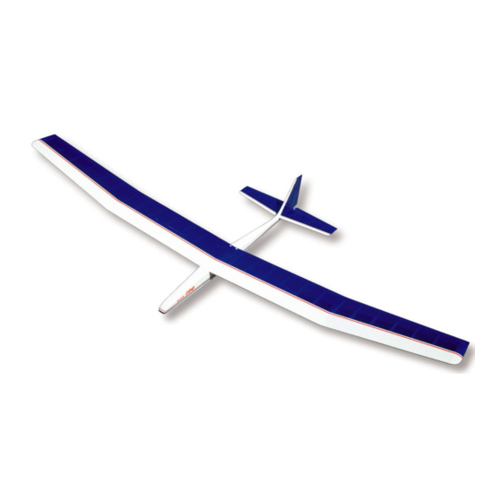
INTRODUCTION
The RISER 100 is a standard class sailplane designed for sport and competition glider pilots alike. It's everything a "glider
guider" could want in an all around sailplane - ease of building, large size, and great "hang time"! With a 100 inch wingspan and
1000 sq. in. of wing area, the RISER 100 is one of the best floaters around. A modified Eppler-205 airfoil lets the RISER 100
maximize any available lift, while still allowing excellent penetration on windy days. It's outstanding flight performance puts it right
at home riding the thermals on a lazy summer afternoon, or going all out in competition against the big guys on contest day.
First-time glider builders will appreciate the straight forward, speedy construction of the RISER 100. The fuselage is built almost
entirely of SIG LITE-PLY using our popular "Tee Lock" construction, which practically assures the builder of a straight, strong
model. A carefully thought out building sequence takes the builder right from the open box to the flying field. Complete
instructions and materials are also included for incorporating optional spoilers in the wing of the RISER 100. Spoilers are
essential for making consistant spot landings and for other multitask soaring events. You will also need to decide whether you
want to use the standard rubber band wing mounting system shown on the main side and top view fuse plan, or if you want to
convert to the optional bolt-on wing attachment as shown on plate 2 of the plans. Complete instructions and materials are
furnished in this kit for either version.
The versatile RISER 100 can even make a good R/C trainer! Many model clubs around the country like to train student pilots on
a sailplane because of their gentle and slow speed flying characteristics. The slow speed allows the beginner ample time to
develop the skills that are necessary for flying radio controlled models. If you have never flown an R/C model before, we strongly
recommend that you obtain the assistance of a skilled R/C flier before attempting to fly your RISER 100 by yourself.
Radio Equipment Requirements
The RISER 100 requires only elevator and rudder control, so any radio with two or more channels may be used as long as it is
on an aircraft approved frequency.
NOTE: If spoilers are to be used, a radio with at least three channels is required.
Advertisement
Table of Contents

Related Manuals for SIG RISER 100


Summary of Contents for SIG RISER 100
- Page 1 R/C flier before attempting to fly your RISER 100 by yourself. Radio Equipment Requirements The RISER 100 requires only elevator and rudder control, so any radio with two or more channels may be used as long as it is on an aircraft approved frequency.
- Page 2 Notes Before Beginning Construction Any references to right or left refers to your right or left as if you were seated in the cockpit. References to inboard means toward the fuselage, while references to outboard means away from the fuselage. To build good flying models, you need a good straight building board.
- Page 3 Die-Cut Poplar Plywood (Lite-Ply) 1 1/8"x6"x48" Fuselage Sides 1 1/8"x6"x20" Fuselage Top and 1 1/8"x3"x48" Fuselage 1 1/8"x6"x12" W1A and W1B Wing Ribs Formers Bottom Die-Cut Birch Plywood 1 3/32"x4"x6" Servo Rails and 1 1/16"x4"x6" Rib Guages and Polyhedral Braces Fuselarge Doublers Hardware 2 9/32"...
-
Page 4: Fuselage Construction
However, because of the vast use of lite-ply and hardwoods in the construction of the RISER 100, we have found that CA glues seem to work the best for the general construction. - Page 5 2. Tape or rubber band the two fuselage sides together at the rear. 3. Working from the rear forward, slip all of the fuselage formers into place. Put a rubber band around the fuselage at each former location to hold it tightly together. 4.
- Page 6 19. In case you carved too much balsa from the bottom of the hatch and now have a gap, here is a simple method to fix it. Simply cover the wing at the dihedral joint with wax paper and apply a generous amount of Sig Epoxolite putty (or other thick model putty) to the bottom of the hatch and then bolt in place.
-
Page 7: Servo And Pushrod Installation
21. Drill a hole through the bottom of the fuselage and through the fuselage doubler FD for the towhook mounting. Measure the exact location for this hole carefully from the plan, as the towhook position is critical for achieving a good launch of the sailplane. -
Page 8: Wing Construction
WING CONSTRUCTION Left Inboard Panel a. Begin by pinning in place the 5/16"x1-1/4"x26" notched balsa trailing edge over the plans. NOTE: Make sure that you identify the correct trailing edge for each of the four wing panels, the notch spacing is different for each. -
Page 9: Wing Center Section
37. Trim to fit and glue in place the 1/16"x1"x4" balsa shear webs at the locations shown on the plans. Optional Spoiler Installation IMPORTANT NOTE: If you have elected not to install the optional spoilers on your Riser 100, skip the following steps 38 through 43 and go directly to step 44 to finish the center section. - Page 10 43. Also, drill 1/8" holes through the W1B and W-2 ribs shown on the plan to allow the plastic tubing to pass through them. In addition, cut a small hole in the bottom center sheeting, just behind the spruce spar, where the plastic tube should exit the wing.
- Page 11 46. Cut out the rib notch pattern. Tape it in place on Rib W1A, and then notch out the rib as per pattern. 47. With a sanding block, bevel one end of each 3/8"x1-5/16"x2-7/16" balsa wing block to match the angle of the W1A rib. Epoxy glue the blocks in place between the ribs W1A and W1B of each wing panel.
- Page 12 Outer Left Panel a. Pin in place the 5/16"x1-1/4" notched balsa trailing edge over the plans. Make sure that you have the correct trailing edge for each panel. b. Pin in place the 3/16"x3/8"x24" spruce spar, making sure you leave a small amount of excess on each end of the wing panel.
- Page 13 66. Pin down the inboard panel over the plan. Position the outboard panel on the plan against the inboard panel and raise the wing tip 3-3/4" as shown. If the joint between the two panels does not match perfectly, sand one or both of the ribs until it does.
-
Page 14: Stabilizer And Elevator
73. Disassemble the wing panels and cut off the dowel pin so that only 3/4" sticks out of the left wing panel W1A rib. Round the end of the dowel pin with sandpaper. STABILIZER AND ELEVATOR 74. Use a modeling knife or a jig saw to cut all of the tail surface parts (S-1, S-2, S- 3, FG, RG-1, and the Dorsal Fin) out of the 1/4"... -
Page 15: Fin And Rudder
FIN AND RUDDER 84. Cut the rudder pattern from plan Plate 2 and tape it in place right behind the fin plan on Plate 1. 85. Glue and pin all pieces of 1/4"x5/16" balsa for the fin and rudder in place over the plans. - Page 16 92. Using your hot sealing iron (set a 200 deg. F for Sig Supercoat), tack down the covering material at several places around the outside edges. Once it is smoothly tacked in place, work completely around the edges, sealing the covering entirely to the structure.
- Page 17 Move the heat gun or iron back and forth over the surface of the wing, allowing the heat to shrink all of the covering on that side at the same rate. Keep the heat gun moving at all times, about 4" to 6" above the covering. If you stop moving for too long, or hold the gun too close, you might melt a hole in the covering.
-
Page 18: Final Assembly
INSTALLING EASY HINGES 105. Using a No. 11 X-Acto blade (or similar) cut slots in the control surfaces approximately 1/2" in depth and slightly wider than the hinge at the locations shown on the plans. Continue cutting all of the slots in all the places to be hinged. 106. - Page 19 114. Epoxy the fin permanently onto the stabilizer and into the die-cut slot in the fuselage top at the same time. Also, insert the bottom rudder hinge into the fuselage when gluing the fin in place. Use a triangle to align the fin with the stabilizer, pin securely in place, and allow to dry.
- Page 20 R/C soaring. The rearward location is for more experienced pilots. A more rearward balance point or Center of Gravity (C.G.) will give the RISER 100 a flatter glide but it will also make it more sensitive to control movements. A forward C.G.
-
Page 21: First Test Flight
A model and radio that is not prepared and working properly on the ground before take-off will not improve in the air - IT WILL GET WORSE! There is no point attempting to fly until everything is 100% correct. FLYING THE RISER 100 First Test Flight While it is possible that a R/C sailplane can be mastered by a beginner without any assistance, the odds of success are pretty slim. - Page 22 High-starts come in several different sizes to match the class of the sailplane being flown - a standard class hi-start is recommended for the RISER 100. The standard class high-start usually consists of 100 feet of rubber surgical tubing and 350 feet of nylon cord (although some brands may differ slightly).
-
Page 23: Slope Soaring
Now that the sailplane is at altitude, it is time to go thermal hunting. Start by trimming the RISER 100 for a nice flat glide and head upwind flying a zig-zag pattern. Never cover the same ground twice while searching for thermals. Be looking for areas where you can see heat waves radiating up, or hawks circling, or swirling "dust devils"... - Page 24 LIMIT OF LIABILITY: In use of our products, Sig Mfg. Co.'s only obligation shall be to replace such quantity of the product proven to be defective. User shall determine the suitability of the product for his or her intended use and shall assume all risk and liability in connection...
Need help?
Do you have a question about the RISER 100 and is the answer not in the manual?
Questions and answers