Advertisement
PARTS INVENTORY
We understand how anxious you are to get started building and flying your SKYRAY, but before you do, please take a few
minutes to inventory the contents of this package. Inside the box you should find:
If you are missing any of these items, call SIG to obtain the missing parts.
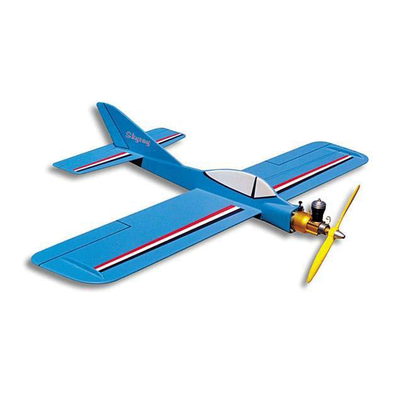
One-Piece Sheet Balsa Wing
Die-Cut Balsa Profile Fuselage
Die-Cut Sheet Balsa Tail Surfaces
Die-Cut Plywood Parts
Formed Wire Pushrod
Nylon Bellcrank
Nylon Control Horn
Decals
Hardware Pack
Illustrated Instructions
Advertisement
Table of Contents

Subscribe to Our Youtube Channel
Related Manuals for SIG SKYRAY


Summary of Contents for SIG SKYRAY
- Page 1 PARTS INVENTORY We understand how anxious you are to get started building and flying your SKYRAY, but before you do, please take a few minutes to inventory the contents of this package. Inside the box you should find: One-Piece Sheet Balsa Wing...
-
Page 2: Tools Needed
Complete all the construction steps 1 through 22 to build your SKYRAY. Work slowly and follow the building instructions exactly. In order for your SKYRAY to fly as well as was designed to, it must be properly assembled. A model airplane that is not built properly will not fly properly! We can provide you with a proven design, quality materials, and detailed instructions, but ultimately the flight characteristics of your finished model depends on how well you put it all together. - Page 3 Thread one end of the DACRON LINE through the top and bottom holes in the control handle as shown. Continue pulling the line through until both lines coming from the handle are the same length. Tie the ends of the control lines securely to the LINE CONNECTORS and cut off any excess line. The final distance between the center-line of the model and the center-line of the control handle should be 27-30 feet.
-
Page 4: Starting Battery
CONTROL HANDLE SENSITIVITY ADJUSTMENT Three sets of holes are molded into the handle to allow changing the CONTROL HANDLE SENSITIVITY. Moving the control lines closer together at the handle will lessen the amount of elevator travel for the same amount of handle movement. - Page 5 Connect the glow plug clip to the ENGINE TROUBLESHOOTING CHART glow head of the engine. The WHAT YOU SEE WHAT TO WHAT YOU SHOULD DO bottom of the clip should rest on AND HEAR LOOK FOR top of the glow head. WILL NOT START.
-
Page 6: Engine Storage
LIMIT OF LIABILITY: In use of our products, Sig Mfg. Co.'s only obligation shall be to replace such quantity of the product proven to be defective. User shall determine the suitability of the product for his or her intended use and shall assume all risk and liability in...
Need help?
Do you have a question about the SKYRAY and is the answer not in the manual?
Questions and answers