Table of Contents
Advertisement
Quick Links
Sig Mfg. Co., Inc....401-7 South Front Street....Montezuma, Iowa 50171
Historically, the Smith Miniplane is one of the designs responsible for the current popularity of small homebuilt biplanes. In 1957,
before the E.A.A. BIPLANE, the SKYBOLT, the STARDUSTER, or the ACRO SPORT, homebuilding consisted mainly of the
FLY BABY design and a few PITTS SPECIALS. Out of a garage in Fullerton, California came a small biplane that was new,
simple and cute. Designed and built by Frank Smith, and designated DSA-1 (DARNED SMALL AIRPLANE), it was an
outstanding example of engineering with the amatuer homebuilder and pilot in mind. It could be constructed with tools easily
within reach of the average craftsman, and its nimble, yet stable, flight performance covered the capabilities of most week end
pilots. Powered by a 100 hp Lycoming. Frank's prototype proved to be fully aerobatic, cruised at 120 mph, and climbed at almost
2,500 ft. per minute. The top wing spanned 17 ft., the fuselage was 15 ft. long, and the empty weight was just over 600 pounds.
Work was started on a second Miniplane and on a detailed construction plan set for sale to the Miniplane's new enthusiasts.
Frank Smith died before either were finished, but his co-workers completed the plans which resulted in dozens of examples
being built.
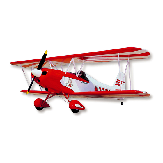
In 1974, Glen Sigafoose, President of Sig Mfg. Co., acquired a completed Smith Miniplane that had been constructed in 1967.
Glen's Smith sports a dazzling red, white, and black paint scheme and was the inspiration for this mini version of the Miniplane.
About The Model
This Miniplane model was designed with easy, yet scalelike construction and good flight characteristics in mind. The exact
scale outlines have been modified where it was thought necessary to obtain optimum areas, moments, and cross-sections for
stable sport flying and aerobatics. Yet its strong resemblance to the full size Miniplane makes it a serious contender in AMA
Sport Scale.
Advertisement
Table of Contents

Related Manuals for SIG SIGRC38


Summary of Contents for SIG SIGRC38
- Page 1 In 1974, Glen Sigafoose, President of Sig Mfg. Co., acquired a completed Smith Miniplane that had been constructed in 1967. Glen's Smith sports a dazzling red, white, and black paint scheme and was the inspiration for this mini version of the Miniplane.
- Page 2 Wax paper should be used to protect the plan during building when the glue used is epoxy or an alphatic resin glue such as Sig-Bond. If a model cement like Sig-Ment is preferred, use plastic wrap to protect the drawing. This type of glue can dissolve the wax out of wax paper which will inhibit drying.
- Page 3 Read these instructions completely and study the full size plan before beginning to work. MAIN CONSTRUCTION Any reference to right or left refers to right or left as if seated in the cockpit. 1. Fuselage Main Frame a. Cut the nose doublers, wing saddles, and the tail posts from the 1/4"...
- Page 4 The recommended engine installation, using a side mounted engine, is shown on the plan. The original models used no engine offset to the right or down and this gave good results. It is easiest to install the engine mounts before the firewall is attached to the fuselage.
- Page 5 Glue the 1/4"x1/2" pieces inside the fuselage frame with the trued side up. Position the line drawn on them exactly on the top of the fuselage sides - with 1/4" protruding above the sides. The top of the pieces must be parallel to the top of the sides so that the plywood platform F10 will also be parallel and thus set the wing incidence at 0 degrees.
- Page 6 Low spots in the seam can be filled with Sig Epoxolite putty. Don't put on too much Epoxolite and expect to sand away the excess later. Epoxolite dries very hard and must be worked into the final desired shape before it hardens.
- Page 7 The strength of the cowling may be increased by lining the inside with fiberglass cloth and resin. This leaves the outside surface smooth and easy to paint. The photos show a Sig Kommander cowl, but the same method applies to the Miniplane cowl.
-
Page 8: Landing Gear
6. Landing Gear Assembly of the landing gear requires the constructed fuselage. Place the 1/8" landing gear wires into the grooved hardwood blocks. Screw the retaining straps in place. Bind the legs of the 1/8" rear brace wire to the main landing gear legs with copper wire. Solder securely. Use sufficient soldering paste to flow the solder completely around and through the bindings. - Page 9 All parts 51, 52, & 53 from the printed sheet. Add remaining 1/4"x1/2" balsa pieces - the stab. leading edges, the elevator trailing edges and the sides. The 1/8"x1/4" balsa ribs. The 1/4" gussets S4 in the elevators. When dry, sand the outside edges to a rounded shape.
- Page 10 Glue the remaining ribs to the spars. Sig-Bond glue is recommended. Fit the shaped trailing edge into the jig ledge on the back of the WI ribs. Trim parts wherever necessary to make the trailing edge fit snugly against the ribs.
- Page 11 Add 1/16" sheeting to the bottom of the wing in the same manner in which the top sheeting was done. Cut away the bottom sheeting under the hardwood insert blocks where the cabane struts will attach. (See fuselage side view.) Sand the front of the wing leading edge with a sanding block.
- Page 12 When satisfied with the alignment of all the wires, solder the copper wire bindings. Use a good hot iron and sufficient soldering paste to flow the solder completely around and through the bindings. The 1/8"x3/4"x4-3/16" plywood strips are held to the upper arms by a brass strap. Drill some random glue anchor holes in the strap.
- Page 13 Sand the entire wing carefully with a sanding block. Glen Sig's Smith Miniplane and the first prototype model at Sig Field. 12. Ailerons (See illustration sequence on the plan.) Locate the rear spar under the 1/16" x 7/8" strips. Draw guide lines on both the top and bottom strips about 1/32" behind this spar so that there is no danger of cutting into the spar in the next step.
- Page 14 Remove the blade from a X-Acto razor saw by prying apart the crimped metal backing with a screw driver. Insert the blade into the slits just cut into the planking and saw through each of the ribs of the aileron. Saw through the trailing edge and remove the ailerons.
- Page 15 Hold the wing in position and locate the proper spots on the bottom of the wing to drill through to hit the hardwood wing blocks in the desired location. Drill through the wing and anchor blocks with a No.7 drill. Tap the hardwood blocks with a 1/4-20 tap.
- Page 16 The plastic parts may be brushed or sprayed with Sig Supercoat color dope. Care should be taken not to apply heavy, wet coats of color dope to the plastic. Put on light coats and allow them to dry thoroughly before applying a second coat.
- Page 17 The following steps outline the finishing coats that were used on the prototype models to duplicate the color scheme of Glen Sig's Smith. Spray three coats of Brilliant White Supercoat Dope on the entire airplane including the plastic parts. Refer to previous section for notes on painting the plastic parts.
- Page 18 Sand the bottom of the ABS plastic headrest as necessary to get a good fit on the top of the fuselage. Glue it in place on the top of the fuselage. Glue it in place with Sig-Ment, used sparingly. Paint the headrest Brilliant White - refer to Sanding and Painting Plastic Parts section.
- Page 19 Servos for which plastic mounts are not available can be screwed directly to at least 3/8" square hardwood rails placed across the cabin as shown in the accompanying drawing. With rubber grommets installed in the servo mounting holes, mark the spots for drilling the pilot holes for screws.
- Page 20 (Rocket City #07, SIGSH84, or solder clevises) are available from the Sig Catalog for securing the pushrod wires to the servos. Or you can make a "Z" bend in the end of the wires as shown.
- Page 21 Be certain to carefully range check your radio equipment and see how it operates with the engine running before attempting test flights. A lot of problems can be avoided if the engine has been well broken in and the idle adjustment perfected on a test block or in another airplane before installation in the model.
- Page 22 LIMIT OF LIABILITY: In use of our products, Sig Mfg. Co.'s only obligation shall be to replace such quantity of the product proven to be defective. User shall determine the suitability of the product for his or her intended use and shall assume all risk and liability in connection...
Need help?
Do you have a question about the SIGRC38 and is the answer not in the manual?
Questions and answers