Table of Contents
Advertisement
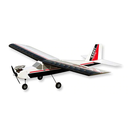
Shown with optional Spinner
(not supplied)
DESIGNED FOR GLOW OR ELECTRIC POWER
WARNING: Radio controlled model airplanes must be used responsibly! Just like a full-size airplane, they fly at a high rate of speed and are capable
of causing serious bodily injury and property damage if they crash. IT IS YOUR RESPONSIBILITY AND YOURS ALONE TO:
(1) Assemble this model airplane correctly according to the instructions.
(2) To ground test the model before each flight to make sure it is completely airworthy.
(3) To always fly your model in a safe approved location, away from populated areas.
(4) To always fly your model in a safe manner. Your first test flights should be made with the assistance of an experienced R/C flyer.
LIMIT OF LIABILITY: SIG Mfg. Co., Inc. guarantees this kit to be free from defects in material and workmanship at the date of purchase. The
actions, skills, and attention to detail of the modeler in assembling and flying this model airplane will ultimately determine its success and safety. Sig
Mfg. Co.'s only obligation shall be to replace those parts of the kit proven to be defective or missing. The user shall determine the suitability of the
product for his or her intended use and shall assume all risk and liability in connection therewith.
SIG MFG. CO., INC. PO Box 520 Montezuma, IA 50171-0520
www.sigmfg.com
Kit No. SIGRC67EGVARF
Wing Span: 70 in. (1778 mm)
Wing Area: 900 sq.in. (58.1 dm2)
Length: 57 in. (1447 mm)
Flying Weight: 6 - 6.25 lbs. (2720-2835 g)
Wing Loading: 15-16 oz./sq.ft. (47-49 g/dm2)
Radio Required:
4-Channel with 5 Standard Servos (glow)
4-Channel with 4 Standard Servos (electric)
Glow Power:
2-Stroke .40-.46 cu.in. (6.5-7.5 cc)
4-Stroke .40-.54 cu.in. (6.5-8.8 cc)
Electric Power:
500-800 watt Brushless Motor (800-1000 kv);
50-75A Speed Control (ESC)
3S-4S 4000-5000 mah Lipo Battery Pack
© Copyright 2014, SIG Mfg. Co., Inc.
Advertisement
Table of Contents

Related Manuals for SIG KADET LT-40 EG


Summary of Contents for SIG KADET LT-40 EG
- Page 1 (4) To always fly your model in a safe manner. Your first test flights should be made with the assistance of an experienced R/C flyer. LIMIT OF LIABILITY: SIG Mfg. Co., Inc. guarantees this kit to be free from defects in material and workmanship at the date of purchase. The actions, skills, and attention to detail of the modeler in assembling and flying this model airplane will ultimately determine its success and safety.
-
Page 2: Assembly Manual
Welcome to the sport of radio control flying, and thank you for choosing the SIG KADET LT-40 EG ARF. In order for your KADET to fly as well as it was designed to, it must be properly ADDITIONAL ITEMS YOU WILL NEED TO PURCHASE assembled. - Page 3 A good running, reliable engine is a minimum requirement for the Note that the BEC feature in some ESCs does not work with 4 enjoyment of this or any R/C model aircraft. cell and larger lipo battery packs - only 3 cell packs. Check the manual of your particular ESC to learn if this is true in your case.
- Page 4 K (2) Formed Main Landing Gear Wires and materials available: K (2) Nylon Landing Gear Straps, for main gear wires A selection of glues - SIG Thin & Medium CA Glue, K (4) M3 x 15mm Screws; for landing gear straps CA Accelerator, CA Debonder,...
- Page 5 Please check the contents of your kit box with these diagrams. If any parts are missing, contact SIG Mfg. Co. at 641-623-5154. The parts shown above are not all to the same scale. Smaller parts are unlarged for clearer viewing. You can measure the length of the bolts and screws using this metric ruler.
-
Page 6: Covering Material
After you have all the covering secured onto the solid areas, turn COVERING MATERIAL the temperature of the iron up to approximately 300 F - 320 (149 C - 160 C). This is the correct temperature for shrinking Your KADET LT-40 ARF is covered with ORACOVER , a pre- ®... -
Page 7: Installing The Aileron Servos
b) Now carefully insert the exposed portion of the four hinges into the trailing edge of the wing. You will find it easiest to slide the hinges into the slots at angle, one hinge at a time, instead of trying to push it straight onto all the hinges at once. c) Adjust the aileron so that the tip of the aileron is flush with the wing tip. - Page 8 INSTALL AILERON CONTROL HORNS & PUSHRODS metal clevis halfway onto the threaded end of the Aileron From the kit contents locate: Pushrod Wire. (2) Nylon Control Horns (6) M2 x 15 mm Screws (2) 7-1/8” long Pushrod Wires with Hex Nut (2) Metal R/C Clevis (2) Pushrod Snap Keepers (2) small pieces of Fuel Tubing...
-
Page 9: Fuselage Assembly
fuselage. The tab that is formed by the two panels at the center, leading edge, fits into the cutout in the front fuselage former. At the rear, two M6.5 nylon wing bolts secure the wing to the fuse- lage. If you encounter any difficulties mounting the wing to the fuselage, find the problem and fix it now. -
Page 10: Install The Landing Gear
INSTALL THE LANDING GEAR K 14) Slide a wheel collar onto the axle of nose gear wire. Slide For the following steps you will need: it all the way up against the bend of the wire, as far as it can go. (1) Fuselage Tighten the wheel collar set screw firmly. - Page 11 e) Unclip the clevis from the rudder control horn so that you K 16) Install the rudder and elevator servos inside the fuselage can now pull the wire pushrod as far forward into the radio com- in the built-in plywood radio mounting tray. The rudder servo partment as possible, to make is easier to complete this step.
-
Page 12: Electric Power System
NOSE GEAR PUSHROD For this section you will need: (1) Fuselage Assembly (1) 19-3/4" long Pushrod Wire with Z-Bend on one end (1) Metal Pushrod Connector K 19) The nose gear pushrod consists of a wire pushrod with a Z-bend on the end that hooks to the nose gear steering arm; and a metal pushrod connector on the servo end. - Page 13 measurement is 2-7/8”. So 4-3/8” minus 2-7/8” = 1-1/2”. Your re- back side of the firewall. Put a couple drops of glue on the sult may be different depending on your motor.) flanges of the blind nuts to secure them to the plywood. Be care- c) Carefully measure and mark the distance determined in the ful not to get any of the glue in the threads.
- Page 14 b) Decide on a good location for the ESC in the nose of the airplane and figure out the best way of routing the motor wires. The most likely location to mount the ESC is against one of the fuselage sides, out of the way of the battery pack. Make sure the ESC is mounted low enough that it does not interfere with the fit of the Hatch.
-
Page 15: Fuel Tank Installation
reach the back of the tank, without getting stuck on the walls of GLOW POWER SYSTEM the tank. Test fit in the tank and adjust as necessary. With the Skip this section if your using an electric power setup. stopper assembly in place, the fuel clunk should sit just in front of the rear of the tank and move freely inside the tank. -
Page 16: Engine Mounting
the firewall. This is the correct distance needed for the cowling to fit properly. K 34) Double check to make sure that the engine is situated square on the mounts, and then carefully mark the locations of the engine mounting holes onto the beams of the engine mounts. K 35) Now set your engine aside and unbolt the engine mounts from the firewall. -
Page 17: Throttle Pushrod
K 40) Screw the nylon clevis onto the threaded end of the pushrod. Then test fit the throttle pushrod wire in the airplane, sliding the plain end of the wire in from the front. Steer the pushrod through the slotted hole in the firewall; then through the hole in the rear tank support;... - Page 18 make sure there is no binding in the throttle linkage, which could opening is big enough for you to slip it over the engine and place cause unnecessary battery drain. it in correct location on the model, then continue modifying the opening as needed to provide access to the needle valve and Ideally, this is the range of throttle moment you want to achieve: the fuel line tubing at the carb.
-
Page 19: Finish The Radio Installation
A standard "Y-harness" chord (not supplied) is needed to connect FINISH THE RADIO INSTALLATION the two aileron servo chords to the receiver. Plug the single end Both glow and electric power users resume assembly here. of the Y-harness into the aileron port of the receiver. It will remain plugged into the receiver permanently, even when the wing is NOTE: The receiver and servos of different brand radios are not taken off the airplane. -
Page 20: Control Surface Travel
model balanced simply by re-locating the battery pack, then you find out if there is an R/C club and flying field in your area. The will have to purchase lead weights from your hobby dealer and local club field is the ideal place to fly your new Kadet! Joining glue them into the tail end of the fuselage.
Need help?
Do you have a question about the KADET LT-40 EG and is the answer not in the manual?
Questions and answers