Advertisement
Quick Links
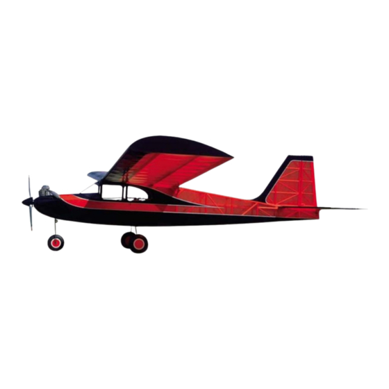
The Kadet Senior basically follows the philosophy of our other models in the
Kadet Trainer series that preceded it, a stable, high wing design using a flat
bottomed airfoil. The major difference is that the wing loading has been reduced
by increasing the size and simplifying the structure. It is more of a "hands off"
flier because of increased dihedral and larger tail surfaces, but because of this,
will not be suitable for aileron control and in fact, does not need it. The excellent
performance is mainly a result of the light weight, but because of this, the Senior
cannot be as rugged as the Kadet Jr. and MKII. The Senior should not be flown
in winds over 10m.p.h. or in a field with obstructions to run into, or from a bad surface that will cause cartwheels on landing,
until you are a proficient pilot. The Junior and MKII are best for rough flying conditions. But the best approach, in our opinion,
is not to choose between the Senior and the Kadet MKII, for example, but to make use of both. Start with the slower Senior to
develop confidence and automatic reactions. Then go on to the Kadet Mark II for graduation to aileron control. The only
transition between the two airplanes is minor, which can be quickly by-passed with a little ground taxiing experience to get
used to steering the nose with a different hand.
RADIO EQUIPMENT REQUIREMENTS
Selection of radio equipment should be based on the amount of money you wish to spend, the type of airplanes you intend to be
flying and your future goals. If you plan to stay in the hobby and work up to larger airplanes with complete controls, it might be
best to consider the purchase of a four, or more, channel set in the beginning, even though the model is flown on fewer
channels. This would eliminate the necessity of disposing of an initial investment in beginner's equipment of less than 4 channels
and buying a new set when your flying skills are ready for an advanced model. Equipment with nicad rechargeable batteries is
strongly recommended. Dry cell operation is cheaper initially but the money saved is soon wiped out buying replacement dry
cells. Nicads are safer, since you go out flying with a full charge and don't have to worry about losing control from dead batteries.
Advertisement

Subscribe to Our Youtube Channel
Related Manuals for SIG KADET SENIOR


Summary of Contents for SIG KADET SENIOR
- Page 1 The Kadet Senior basically follows the philosophy of our other models in the Kadet Trainer series that preceded it, a stable, high wing design using a flat bottomed airfoil. The major difference is that the wing loading has been reduced by increasing the size and simplifying the structure.
- Page 2 In addition to the instructions you are reading now, the publication "The Basics of Radio Control" has been included with this kit as a reference for installing the engine, fuel tank, and radio in the Kadet Senior. It also contains very important information on preparing the model for flight.
- Page 3 YOU CAN'T GET ALONG WITHOUT A GOOD SANDING BLOCK An indispensable tool for proper construction is a large sanding block, sized to take a full sheet of sandpaper. Use several wood screws along one edge to hold the sheet in place. Use the block to bring all parts and sticks to final, exact fit. I recommend 80 grit garnet paper for use on the block during general construction.
-
Page 4: Wing Construction
Hardware 1 5/32" Nylon Nose Gear 1 5/32" Nylon Nose Gear Steering Arm 1 6-32x1/4" Screw for Steering Arm 1 Package of 7 Easy Hinges Bearing 2 Nylon Control Horns 4 4-40 Blind Nuts for Nose Gear Bearing 4 6-32 Blind Nuts for Engine Mounts 4 4-40x3/4" Screws for Nose Gear Bearing 4 6-32x1"... - Page 5 a. Glue the 1/2" sq. x 36" leading edge into the front of the ribs. 7. Position the center W-1 rib, using the dihedral guage as shown to get it at the right angle. Tack glue only until paragraph 18. NOTE: The Dihedral Guage is not a Micrometer.
- Page 6 14. Finish the front WT with another piece of scrap balsa. 15. Turn the wing over and trim the top 1/16" tip sheeting off flush with the bottom of 16. Trim the trailing edge block off as shown and sand and smooth. 17.
- Page 7 24/3 The wing center joint is reinforced with the strip of 2" wide fiberglass tape. I use regular Sig Epoxy Glue (not Kwik-Set Glue) for applying the fiberglass tape, since it is thinner and easier to spread out smoothly. It will be even easier to spread if you warm the mixing container by setting it in hot water for a few minutes to raise the temperature of the glue.
-
Page 8: Firewall Assembly
FIREWALL ASSEMBLY READ THIS SECTION CAREFULLY In designing a kit, we have to think about the buyers who have never previously built any type of model. For them, extra complications must be absolutely necessary or left off. Therefore, since the Senior will fly quite reasonably and safely without any right thrust offset in the engine, we show it with zero side thrust on the plan. - Page 9 30. With a punch or sharpened piece of of 1/8" wire, center punch the motor mounting holes. (Hint: If you are not used to doing this sort of job, don't try to punch and drill all 4 holes at once. Punch and drill only one hole.
-
Page 10: Fuselage Construction
FUSELAGE CONSTRUCTION a. Soak the front end of the bottom 1/4" sq. fuselage stringer in water so that it may be more easily pinned into place on the plan in the curved part at the front. b. Add the other lengthwise stringers of spruce and balsa. - Page 11 42. A 1/4"x1/2" crosspiece on edge is used at section-D on the bottom. 43. Glue in the bottom 1/4" sq. crosspieces. a. Use two flat sided weights to pull in the fuselage sides at the tail end. b. Check with a 90deg triangle to insure they are directly over the plan.
- Page 12 a. Feather the scrap strips into the lines of the bottom, leaving them full depth where they touch the front sheeting, tapering to nothing at the back. (See fuselage side view.) b. Glue in the 1/4" sq. stringer doublers. a. Glue the hardwood anchor blocks on top of the grooved landing gear blocks and to the insides of the G-3s a.
- Page 13 Modern plastic tanks are virtually indestructable under normal use and bursting or cracking is almost unknown. If you use Sig Heat Proof Silicone tubing (which will not harden or deteriorate in fuel) in the plastic tank, the tank will seldom have to be removed.
- Page 14 64. On the plans we show the servos mounted high in the fuselage for easy access. Some think this spoils the appearance, since they stick up and show through the windows. So in this picture we have a 3-servos-abreast installation mounted a bit lower, below the cabin window line.
- Page 15 Additional pushrod connectors can be purchased (Sig No. SH-736) for use on the throttle Angle the nose gear steering arm and nosewheel servo arms. Adjust by forward in neutral to allow more range of loosening the set screw and sliding the movement.
- Page 16 66. The clear cabin windows are glued to the inside of the die cut ply window frame. Make sure you do it left and right. The main necessity here is to avoid warping this thin assembly. Therefore do not use water base glues such as Sig Bond or Tite Bond.
-
Page 17: Tail Surfaces
71. Glue the cowl halves to the fuselage, flush with the bottom and sides. 72. Carve the cowl sides to a pleasing shape. Add C-3 exactly 1/8" deep from the sanded bottom cowl shape. 73. Cut away the inside of the cowl to clear space for pushrods or engine parts. It is a good idea to carve a taper into C-2 on the inside to make it easier to paint or fuel proof the cowl interior, but do not do this until later, after the front and any top fill-in blocks desired are added. - Page 18 a. A 1/8"x3/8" hardwood brace is glued across the back. b. Next add the 3/8"x3/4" strip center rib. 82. Cut and fit 1/4"x3/8" strips of balsa. a. Pin down the 1/4"x3/8" elevator leading edge. b. Pin down the notched trailing edge, c.
- Page 19 This way, the parts are much easier to handle. A CAUTION ABOUT THE KADET SENIOR WING A recent experience leads us to add further caution to the one here. It is simply: USE ENOUGH GLUE! Even...
-
Page 20: Covering And Finishing
SuperTrim is made of the same material as Supercoat, but it has a sticky backing. Simply cut out your design and stick it in place. Thin strips can be cut from SuperTrim sheets or you can use one of the many brands of striping tape (such as Sig SuperStripe) which come in various colors and widths. - Page 21 Although we refer to silk in the directions, all of these coverings are applied wet in the same manner as follows. Brush an unthinned or very lightly thinned coat of clear Sig Supercoat or Sig Lite-Coat Dope over all parts of the framework that will contact the covering.
- Page 22 Don't bear down on the edges of the ribs or the silk fibers will be cut through. The color dope may be brushed or sprayed. Sig Supercoat Color Dope has low shrinkage qualities. Apply the colored dope to the silk exactly as described in the "COVERING WITH SIG KOVERALL" section, starting with the white base coats.
-
Page 23: Final Assembly
DECALS - Stik-Tite Pressure Sensitive Cut out the decals with a pair of sharp scissors. Leave about 1/32" to 1/16" of clear edge around the decal. Round the corners as you are cutting. Wet the surface on which the decal will be placed with soapy water (use dishwasher detergent). -
Page 24: Control Movements
The suggested balance point for the Kadet Senior is shown on the plan. Balance with an empty fuel tank but with all the other equipment installed and the model completely finished and painted. Suspend the model from the wing tips at the balance point. - Page 25 FLYING To Fly The Kadet Senior On A 4 Channel Radio Plug the rudder servo in the fuselage into the receiver outlet marked aileron.Use of the aileron stick on your radio equipment to operate the rudder will enable you to develop the proper left and right reactions that will later be needed when advancing to aileron control, using the same hand.
- Page 26 RUBBER BANDS ON WING Remember that different brands of rubber bands have different stretch characteristics. Apply some common sense judgement to the number of rubber bands used. It is a good idea to stretch each new band to its limit before using to locate any hidden defects.
- Page 27 LIMIT OF LIABILITY: In use of our products, Sig Mfg. Co.'s only obligation shall be to replace such quantity of the product proven to be defective. User shall determine the suitability of the product for his or her intended use and shall assume all risk and liability in...
Need help?
Do you have a question about the KADET SENIOR and is the answer not in the manual?
Questions and answers