Table of Contents
Advertisement
Quick Links
A / V
D I S T R I B U T I O N
SERVICE MANUAL
PR-4Zi
1
1
2
1
A
LL
P
OWER
O
N
3
4
A
LL
O
FF
Z
S
ONE
ELECT
&
C O N T R O L
S
OURCE
2
3
4
5
6
2
3
4
O
/O
B
T
N
FF
ASS
REBLE
S Y S T E M S
4
Z
—
6
S
A
/ V
P
O N E
O U R C E
U D I O
I D E O
R E A M P L I F I E R
V
OLUME
SOURCE LINK
SOURCE / VOL LINK
L
P
M
P
OUDNESS
ARTY
EMORY
RESET
CP 4.6
Advertisement
Table of Contents

Related Manuals for Russound CP 4.6


Summary of Contents for Russound CP 4.6
-
Page 1: Service Manual
O U R C E U D I O I D E O R E A M P L I F I E R OURCE OLUME OWER SOURCE LINK SOURCE / VOL LINK REBLE OUDNESS ARTY EMORY RESET ELECT CP 4.6... - Page 2 CP 4.6 4-Zone, 6-Source Audio/Video Preamplifier INSTRUCTION MANUAL...
-
Page 3: Important Safeguards
Canada the label will read AC120V, 60Hz. or near a swimming pool. 4. Do Not Touch The CP 4.6 With Wet Hands – Do not handle the CP 4.6 6. Carts and Stands - The appliance should be used only or power cord when your hands are wet or damp. -
Page 4: Table Of Contents
Control Functions ....10 CP 4.6 Control Functions ....10 Memory Procedure ....11 Preset Procedure . -
Page 5: Product Overview
PTM-1 Paging Modules add whole-house paging Interface connections are provided for cascading as capabilities. many as four CP 4.6s. An RS-232 port allows the CP 4.6 Wiring Instructions AUDIO/VIDEO SOURCES Make line level and composite video connections from source equipment to the CP 4.6 as shown in Figure 1. -
Page 6: Connecting Amplifiers
Wiring Instructions CONNECTING AMPLIFIERS Connect the Zone Output of each CP 4.6 zone to one amplifiers, such as the Russound DPA-1.2, connect as line input of a multichannel amp. Figure 2 shows a shown in Figure 3 (see p. 6). Use good quality audio connection to the Russound DPA-6.12 Twelve Channel... -
Page 7: Common And Zone Trigger Outputs
NPUT COMMON AND ZONE TRIGGER OUTPUTS Figure 4 – Common and Zone trigger outputs The CP 4.6 provides four Zone-Specific and one Common +12VDC trigger outputs (Figure 4). The Zone-Specific triggers are turned on when the corresponding zone is on. The Common trigger is turned on when any zone is on. -
Page 8: Connecting Video Monitors
CONNECTING VIDEO MONITORS Each CP 4.6 zone has a composite video output to allow viewing video from any of six A/V sources. Connect monitors as shown in Figure 5 using RG6U cable with RCA type connectors. If more than two monitors are being used in a zone, a composite video distribution amplifier is recommended. -
Page 9: Creating Subzones
FIXED ZONE LINE OUT: CREATING SUBZONES The CP 4.6 has six buffered, fixed-level audio/video outputs as shown previously in Figure 1 (p. 4). When set to FIXED ZONE LINE OUT (Figure 7), the last four outputs can be used to create subzones of each main zone. -
Page 10: Page Trigger Output
Wiring Instructions PAGING TRIGGER OUTPUT MUTE INPUT The CP 4.6 is equipped with a paging trigger output The CP 4.6 system mutes when a +12VDC signal is (Figure 8) that switches on during a page. This output applied to the mute input (Figure 8). This allows can be used to trigger an external amplifier, muting connection of external paging or muting devices. -
Page 11: Control Functions
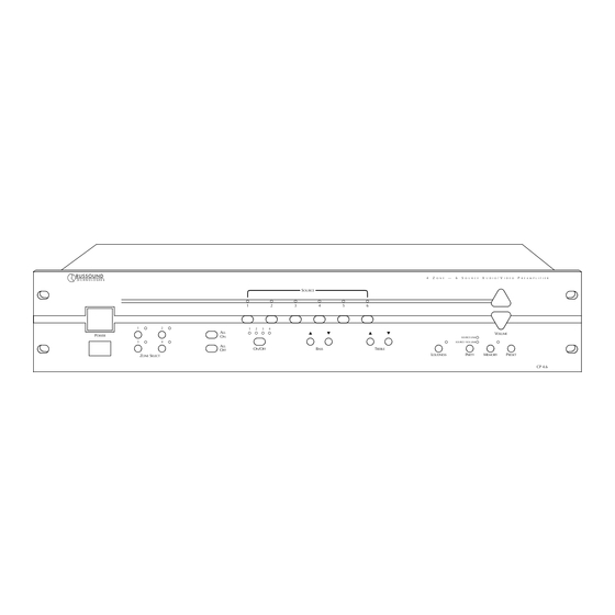
Control Functions Figure 9 – CP 4.6 control functions — O N E O U R C E U D I O I D E O R E A M P L I F I E R OURCE OLUME OWER... -
Page 12: Memory Procedure
PRESET PROCEDURE PRESET recalls settings for the current zone previously stored in memory. A preset can be recalled at the CP 4.6 front panel, on a PCK keypad, or via the PRC-1 remote control. 1. Select a zone using ZONE SELECT. -
Page 13: Peripheral Devices
Peripheral Devices PCK KEYPADS IR DEVICES Each of the CP 4.6’s zones can be remotely operated by The keypad ports are also compatible with infrared a keypad or IR device. There are four keypad ports on devices such as Russound 848, 1257, 1258, and 844 the rear panel. -
Page 14: Pck Keypad Control Functions
PCK KEYPAD CONTROL FUNCTIONS Infrared Receiver – Receives IR commands from LOUD – Selects and indicates loudness on/off. Russound PRC-1 remote or a source component’s Source Select – Selects and shows input source. remote. SELECT – Selects function (bass, treble, SYSTEM ON –... -
Page 15: Paging
Use 22-24 AWG twisted pair shielded wire to connect except the zone where the page originates. The PAGE the SPG to the CP 4.6 page input as shown in Figure 13. ALL input will allow paging to all zones. A page turns on... -
Page 16: Ir Emitters
Peripheral Devices IR EMITTERS Figure 15 – Source-specific infrared outputs The CP 4.6 has seven IR outputs: Source 1–6 and Common. Source 1–6 outputs are source-specific and provide IR signals only to the selected source; the Common output provides IR signals to all sources. -
Page 17: Prc-1 Remote Control
The Russound PRC-1 remote control is preprogrammed to operate more than 1,000 audio and video components, including the CP 4.6. Set it up by simply punching in a three-digit code that matches your equipment. The PRC-1 also has the ability to learn new functions, allowing you to customize it and update it as you add new equipment. -
Page 18: Multiple Controllers
Multiple Controllers INSTALLING MULTIPLE CP 4.6 CONTROLLERS Your CP 4.6 may either have 2 female DB-25s or As many as four CP 4.6s can be cascaded via DB-25 1 male and 1 female DB-25. For units equipped with connectors. Cascading links multizone functions such as... -
Page 19: Using The Rs-232 Comm. Port
RS-232 COMMAND PROTOCOLS Commands are sent from RS-232 controlling device to the CP 4.6 as 8 ASCII bytes. The first two ASCII bytes “RU” establish that the command is a Russound command for zone commands only. The next 3 bytes “Z01” establish the zone to be controlled. -
Page 20: Rs-232 Commands
RS-232 Commands & Update Values MULTI-ZONE COMMANDS RUALZOZN all zones on RUALZOZF all zones off RUSORCLC party mode (source link) RUSORCLN party mode (source/volume link) ZONE COMMANDS Zone number (XX) can be between 01 and 16. Use the addressing switch (Figure 19) to set zone numbers (01-04), (05-08), (09-12), (13-16) RUZXXZON zone on RUZXXSR2 source input 2... -
Page 21: Technical Specifications
Dimensions: 19" W x 12" D x 3.6" H. Weight: 12 lbs. The CP 4.6 complies with the requirements of the standards for Audio Video Products and Accessories (UL 1492, 1st Edition) and Radio, Television, and Electronic Apparatus (CSA C22.2 No. 1-M94). -
Page 22: Warranty & Repair
Warranty & Repair The Russound CP 4.6 is fully guaranteed against all defects in materials and workman- ship for two (2) years from the date of purchase. During this period, Russound will replace any defective parts and correct any defect in workmanship without charge for either parts or labor. - Page 23 Russound Technologies 5 Forbes Road, Newmarket, NH 03857 tel 603.659.5170 • fax 603.659.5388 e-mail: tech@russound.com www.russound.com fax-on-demand: 603.659.5590 28-0097...
- Page 24 PR-4Zi and CP4.6 TEST PROCEDURE The purpose of this Test Procedure is to instruct not only the Russound Test Department on how to test the product but to instruct any outside Service Technician that might need to do so as well. There are several pictures throughout the Test Procedure to help the technician test the product.
- Page 25 Equipment Needed: Line Level Audio Source (Tuner) CP4.6 CP4.6 Diagnostic Program Speakers CP4.6 Instruction Manual 12Volt LED Indicator (1/8 inch jack, LED, 1K ohm resistor) IR LED Indicator 2 845.1 Amplifier PCK-IR DPA 1.2 Power Cord (09-0504) DB-25 Cable RS-232 Cable Inspection: Inspect Sheet Metal for scratches Inspect screening for correct labeling.
- Page 26 6. ALL ON – With all zones off press ALL ON. All zone LEDs should go on. 7. ALL OFF – With all zones on press ALL OFF. All zone LEDs should go off. Figure 1. Figure 2.
- Page 27 Figure 3. 12Volt Trigger Out Test: 1. Turn on all zones by pressing "ALL ON" on the front of the CP4.6. All four zone LEDs on front panel should illuminate. Check the Common 12Volt Trigger Out on rear panel, there should be 12VDC. Check the 12Volt Trigger Outputs (4), there should be 12VDC at each output.
- Page 28 Figure 5. Figure 6. Figure 7.
- Page 29 Note: Steps 3 through 10 should be done on the CP 4.6. 3. Turn Zone 1 on by pressing ON/OFF, the Zone 1 LED should illuminate. 4. Press VOLUME UP the volume should increase. The increase should be heard through both speakers.
- Page 30 Output. Attach the IR LED Indicators to the all Source 1 Emitter Outputs. The Test PCK-IR Keypad should still be attached to the Zone 1 Keypad input. 2. Control Source 1 component with the remote from the PCK-IR Keypad. Ensure the source can be controlled from both the Common IR Output and the Source IR Output.
- Page 31 Disconnect the Right Side of the “Zone 2 ADP-1” output from the Source 1 input. Listen to ensure the Audio is only being heard in one speaker. 7. Reconnect the Right Side of the line level source output to the Source 1 input. Test: Reconnect the Right Side of the “Zone 2 ADP-1”...
- Page 32 3. Put the “A-Bus” Ready switches (4) on the rear of the CP4.6 in the “Fixed Loop Out” position. 4. Ensure that Zone 1 on the front panel is selected to Source 1. 5. Listen to ensure the audio is heard through both speakers. 6.
- Page 33 5. Set Zone 1 to Source 1. 6. Press The Party button once, the Source/Volume Link indicator will light. 7. Zones 2, 3, and 4 should now be on Source 1. 8. Set the CP4.6 for Zone 4 by selecting the Zone 4 button. Change the source to Source 2.
- Page 34 6. Press the SPG Keypad button and speak into the Keypad. You should be able to hear your voice over the speakers. 7. Check the Page Trigger Output on the back of the CP4.6. There should be 12VDC, every time a page is initiated. Test: The LED on the 12Volt LED Indicator should light every time a page is initiated.
- Page 35 RS232 Test: 1. Connect the RS-232 port on the CP 4.6 to the RS-232 communications port on a computer, using a standard DB-9 RS-232 cable. 2. Open the CP 4.6 Diagnostic Program by clicking the CP 4.6 Diagnostic Program Icon on the computer.
- Page 36 7. With one of the CP4.6s with Zone 1 selected, change sources on the front panel. The source change should be seen on both CP4.6s. 8. Set the other CP4.6 for Zone 2, change sources on the front panel. The source change should be seen on both CP4.6s.
- Page 37 CP4.6 Main PCB R2.sch-1 - Thu Apr 05 11:22:21 2001...
- Page 38 CP4.6 Main PCB R2.sch-2 - Mon Nov 17 15:07:04 2003...
- Page 39 CP4.6 Interface PCB R0.sch-1 - Tue Apr 10 10:10:17 2001...
- Page 40 RES 1/4W 5% 1 K 7/1/2002 4.000000 XICON 291-1K RESISTOR 03-0008 ELEC RD 1.0 UF 50V 7/1/2002 4.000000 XICON 140-XRL50V1.0 CAPACITOR 03-0411 CERA. MINI .1UF 50V EPOXY 7/1/2002 1.000000 XICON 21RZ310 CAPACITOR Bill of Materials - Explosion/Implosion Reports, BOMRPT.RPT RUSSOUND PENGEL 7/26/2002 2:22:38 PM...
- Page 41 1.000000 AC-016-B-100 CONNECTOR 09-0400 WIRE UL1015-18-16 RED TC 7/1/2002 2.000000 1K' ROLL WITH TOP COAT WIRE 09-0401 WIRE UL1015-18-16 RED/WHT 7/1/2002 2.000000 1K' ROLL WITH TOP COAT WIRE Bill of Materials - Explosion/Implosion Reports, BOMRPT.RPT RUSSOUND PENGEL 7/26/2002 2:22:38 PM...
- Page 42 CERA. MINI .1UF 50V EPOXY 5.000000 XICON 21RZ310 CAPACITOR 08-0429 CONN FEMALE 2 X 10 1.000000 SIGNTRN #2221-20-S-02-3.0 CONNECTOR 08-0501 CONN DBLE FEMALE DB-25 1.000000 PDI P/N PDI-DDA-P CONNECTOR Bill of Materials - Explosion/Implosion Reports, BOMRPT.RPT RUSSOUND PENGEL 7/26/2002 2:22:38 PM...
- Page 43 RES 1/4W 5% 75 OHM 6.000000 XICON 291-75 RESISTOR 02-0032 RES 1/4W 5% 100 OHM 4.000000 NIC-NCF5J101B RESISTOR 02-0035 RES 1/4W 5% 27K OHM 8.000000 NIC NCF25J273B RESISTOR Bill of Materials - Explosion/Implosion Reports, BOMRPT.RPT RUSSOUND PENGEL 7/26/2002 2:22:38 PM...
- Page 44 12P 3 X4 PARAVOIX PJ1262G PHONO JACK 18-0001 DIODE 1N4148 62.000000 DIODE 18-0308 IC 74F04 1.000000 MC74FO4N SEMICOND 18-0310 IC TL074ACN 2.000000 TEXAS INSTRUMENT SEMICOND 18-0313 IC 74F32 4.000000 SN74F32N SEMICOND Bill of Materials - Explosion/Implosion Reports, BOMRPT.RPT RUSSOUND PENGEL 7/26/2002 2:22:38 PM...
- Page 45 68 PIN PLCC SOCKET 1.000000 PDI # PDSN-504W-068 SOCKET 19-0007 28 PIN PLCC SOCKET 12.000000 PDI # PSDN-504W-028 SOCKET 53-0006 PREAMP PWR SUPPLY 7/1/2002 1.000000 MODEL #LPT42 PWR SUPP. Bill of Materials - Explosion/Implosion Reports, BOMRPT.RPT RUSSOUND PENGEL 7/26/2002 2:22:38 PM...
Need help?
Do you have a question about the CP 4.6 and is the answer not in the manual?
Questions and answers