
Related Manuals for Blizzard B74C


Summary of Contents for Blizzard B74C
- Page 1 SNOWBLOWER BLIZZARD B74C MODEL SERIAL NO. 21502142 AND UP OM 0410SB-A 02/15...
-
Page 3: Table Of Contents
TABLE OF CONTENT SPECIFICATIONS ............................3 INTRODUCTION – TO THE PURCHASER ....................4 SAFETY PRECAUTIONS .......................... 5-11 Before Operation ............................ 5 Notice ..............................6 The Snowblower ..........................6-8 Before Operation........................6 Snowblower Operation ......................7 Stay Clear of Rotating Drivelines ................... 8 The Tractor ............................ - Page 4 Driveline – Troubleshooting ........................ 36-38 PARTS ................................. 39-48 Introduction ..............................39 Manual Holder ............................... 39 Snowblower - B74C ..........................40-42 Gearbox 663485 ............................43 Driveline 4700159 ............................44 BER0077 - Manual Rotation ......................... 45 BER0078 - Hydraulic Rotation ........................46 BER0079A - Hydraulic Deflector ........................
-
Page 5: Specifications
SPECIFICATIONS Features and Specifications B74C Working Width 74" Transport Width 74" Working Height 26" Length 47 3/4" Single/Dual Auger Single Auger Diameter 15" Auger Flighting Thickness 5/16" Impeller Diameter 24" Impeller Width 9" Impeller Shaft Diameter 1 3/8" Number of Impeller blades... -
Page 6: Introduction - To The Purchaser
INTRODUCTION O THE URCHASER All BER-VAC and BLIZZARD products are Illustrations designed to give safe, dependable service if they The illustrations may not necessarily reproduce are operated and maintained according to the full detail and the exact shape of the parts or instructions. -
Page 7: Safety Precautions
SAFETY PRECAUTIONS SAFETY FIRST This symbol, the industry's "Safety Alert Symbol", is used throughout this manual and on labels on the machine itself to warn of the possibility of personal injury. Read these instructions carefully. It is essential that you read the instructions and safety regulations before you attempt to assemble or use this unit. -
Page 8: Notice
SAFETY PRECAUTIONS - continued OTICE A safe operator is the best insurance against accidents. All operators, no matter how experienced they may be, should read this Operator's Manual and all other related manuals before attempting to operate an implement. Please read the following section and pay particular attention to all safety recommendations contained in this manual and those labeled on the implements and on the tractor. -
Page 9: Snowblower Operation
SAFETY PRECAUTIONS- continued Snowblower Operation 11. Do not run the engine indoors except when starting engine and transporting attachment in or 1. Before leaving tractor/snowblower out of building. Carbon monoxide gas is unattended, take all possible precautions. colorless, odorless and deadly. Park the tractor/snowblower on level ground, place the transmission in neutral, set the 12. -
Page 10: Stay Clear Of Rotating Drivelines
SAFETY PRECAUTIONS- continued Stay Clear of Rotating Drivelines 1. Entanglement in rotating driveline can cause serious injury or death. 2. Keep tractor master shield and driveline shields in place at all times. Make sure rotating shields turn freely. 3. Wear close fitting clothing. Stop the engine and be sure that PTO driveline is stopped before making adjustments, connections, or cleaning out PTO driven equipment. -
Page 11: The Tractor
SAFETY PRECAUTIONS- continued RACTOR General Information 14. A minimum 20% of tractor and equipment 1. Read the operator's manual carefully before weight must be on the tractor front wheels using tractor. Lack of operating knowledge when attachments are in transport position. can lead to accidents. -
Page 12: Roll-Over Protective Structure (Rops)
SAFETY PRECAUTIONS- continued Roll-Over Protective Structure (ROPS) 1. DO NOT weld, drill or alter the ROPS. Damaged ROPS must not be straightened or used. If damage does occur, consult your dealer. 2. If the ROPS is lowered or removed from the tractor for any reason, it must be erected and/or refitted immediately. -
Page 13: Maintenance
SAFETY PRECAUTIONS- continued AINTENANCE 10. Do not modify or alter this snowblower or any of ALWAYS USE GENUINE PARTS WHEN its components or operating functions. If you REPLACEMENT PARTS ARE REQUIRED have questions concerning modifications, 1. Keep tractor snowblower consult with your dealer. properly maintained. -
Page 14: Safety Decals
SAFETY DECALS Replace immediately if damaged. 2500833 662699 2500782 2500608 2500783 664517 BLIZZARD 664458 655834 2500783 2500813 2500785 2500786 2500792 OM 0410SB-A... -
Page 15: Assembly
ASSEMBLY RACTOR REPARATION See Dealer for Tractor Preparation information. NOWBLOWER SSEMBLY The snowblower is assembled at the factory except for the parts in the hardware bag provided with the snowblower, the chute and the options if appropriate. Use the present manual and lay out all parts for assembly. -
Page 16: Installation Of Snowblower With Three Point Hitch
ASSEMBLY Installation of Snowblower with Three Point Hitch (Figure 2) 1. Install the two cat.1 pins (item 1) on the right 6. Adjust the snowblower using the tractor upper and left snowblower hitches in the lower holes link so that the snowblower operates parallel to as shown on figure. -
Page 17: Installation Of Snowblower With Quick Hitch
ASSEMBLY Installation of Snowblower with Quick Hitch (Figure 3) CATEGORY 1 only 1. Install the two cat.1 pins (item 2) on the right CAUTION and left snowblower hitches in the upper holes leaving 3 1/4" between the jam nut and Before connecting snowblower driveline to the end of the pin as shown on figure. -
Page 18: Installation Of Manual Rotation Kit Ber0077
ASSEMBLY Installation of Manual Rotation Kit BER0077 (Figures 4-5-6-7) NOTE: The rotation handle can be installed on 6. Figure 5: Install handle support bracket the right or left side of the three point hitch. (item 5) on the bracket (item 1) using a 3/4’’NC x 1 1/2’’... - Page 19 ASSEMBLY 9. Figure 6: Install plastic handle (item 5) over the 14. Figure 7: Make sure the worm engages rotation handle (item 6). completely when it reaches the end of the chute gear. The rotation handle is well 10. Figure 6: Insert assembled rotation tube adjusted when the chute rotates easily (item 1) inside the rotation worm assembly without straining.
-
Page 20: Installation Of Hydraulic Rotation Kit Ber0077
ASSEMBLY Installation of Hydraulic Rotation Kit BER0078 (Figures 8 to 12) 1. Install the chute according to the instructions contained in the snowblower Operator's Manual. 2. Figure 10: Place the motor spacer (item 2) on the motor top (item 1) by aligning the holes. Install the motor (item 1) under the frame base of the snowblower and secure with four 3/8’’NC x 1’’... - Page 21 ASSEMBLY 5. Figure 10: Install a 0.052" flow restrictor (item 2) in each motor input (item 1). 6. Figure INCLUDED: Connect the two hoses (item 3) on the motor flow restrictors (item 2). Direct the hose elbows toward the snowblower upper arm. 7.
- Page 22 ASSEMBLY PROBLEM: HYDRAULIC CHUTE ROTATION IS SLOW OR DOESN'T TURN When activating the chute rotation, it turns very slowly or not at all. WARNING 3. Figure 12: Check if there is residue in the avoid serious personal injury hydraulic circuit. To do so, first verify if the chute always wear safety glasses while doing the rotates well in one direction.
-
Page 23: Installation Of Hydraulic Deflector Kit Ber0079
ASSEMBLY Installation of Hydraulic Deflector BER0079A (Figures 13 to 18) 1. Install the chute according to the instructions in the snowblower Operator Manual. Figure 13 2. Figure 13: Remove the two manual adjustment knobs (item 1) and bolts (item 2) from each side of deflector and replace with two 5/16”... - Page 24 ASSEMBLY 8. Figure 16: Install the hose support (item 1) on the three point upper hitch CAUTION bracket (item 2) right or left (right one is recommended) using two 3/8’’NC x To avoid serious personal injury. Escaping 1 1/2’’ bolts (item 3) and two 3/8"NC hydraulic/ diesel fluid under pressure can penetrate nylon insert locknuts (item 4).
-
Page 25: Installation Of Electric Deflector Kit 8151
ASSEMBLY Installation of Electric Deflector Kit 8151 (Figures 19 to 21 & Electrical Diagram) PRE-ASSEMBLY 1. Figure 19A: Install the clevis with the 1 1/32" 3. Figure 19 & diagram: Connect the wires to diam. hole (item 1) on the actuator base the switch as follows: •... - Page 26 ASSEMBLY ASSEMBLY 4. Figure 20: Retract completely the pre- For Chute with knob adjustment: assembled actuator rod (item 10). Attach the 1. Figure Remove manual actuator to the deflector bracket (item 5) and to adjustment knobs and the bolts on each the base bracket (item 7), with two 1"...
- Page 27 ASSEMBLY Figure 21: Insert the switch (item 1) in the switchbox (item 2), secure with the two nuts (items 3) provided with the switch, and screw the rubber cap (item 4) in the order shown on figure. Insert the plastic cap (item 5) in the free hole of the switchbox (if needed).
-
Page 28: How To Determine Driveline Angles
ASSEMBLY Danger: Tractors Too Big IMPORTANT A proper initial installation will give you years of It is dangerous to use a tractor that is too big and satisfactory service on your equipment. Please powerful. The tractor will always be able to read carefully following instructions that have overload the blower, even if the machine is been specially included to help you and ensure... -
Page 29: Angles At Each End Of Driveline
ASSEMBLY Unequal Angles at Driveline Joints Equal Angles at Driveline Joints Avoid Recommended Angles at Each End of Driveline A popular habit is to change the snowblower angle in order to obtain a better scraping effect. This practice can become harmful to the driveline since the angle at each end is unequal. - Page 30 ASSEMBLY NOTE: Before cutting, make sure the two shafts 6. Figure 23A: File down tubes and remove intersect by at least 7 3/4" when in working chips. position that is when the snowblower rests on the 7. Apply grease to inside of outer telescopic ground.
-
Page 31: Driveline Installation
ASSEMBLY Driveline Installation (Figure 24) 1. Separate the snowblower from the three point or quick hitch. 2. Remove paint from snowblower gearbox shaft (item 1) and grease driveline sliding surfaces and yoke (item 2). 3. Remove the bolts (items 3) from the driveline yoke (item 2) and slide yoke over drive shaft using the sliding action of the driveline. -
Page 32: Removing Snowblower From Tractor
ASSEMBLY Removing Snowblower from Tractor (Figures 25 to 28) Three Point Hitch 1. Set parking brake and turn engine off. 2. Figure 25: Remove the wire round lock pin (item 2), lower the parking stand (item 1) Figure 25 completely to the ground to release all pressure from the three-point and reinsert the wire round lock pin in the lower hole (item 3). -
Page 33: Assembly
ASSEMBLY Quick Hitch 1. Set parking brake and turn engine off. Figure 27 2. Figure 27: Remove the wire round lock pin (item 2), lower the parking stand (item 1) and reinsert the wire round lock pin in the lower hole (item 3). -
Page 34: Operation
OPERATION ENERAL REPARATION DJUSTMENTS 1. Read the operator’s manual carefully before Chain Tension Adjustment using the tractor and snowblower. Be (Figure 29) thoroughly familiar with the controls and The premature wear of the chain may be caused by proper use of the equipment. Know how to tension being too tight. -
Page 35: Snow Removal Methods
OPERATION EMOVAL ETHODS When removing snow, do not use the snowblower as a dozer blade to push snow. Let the snowblower work its way through deep drifts. If the speed of your tractor is too fast, the snowblower may become overloaded and clog. -
Page 36: Maintenance
MAINTENANCE AINTENANCE Shearbolts Check the shearbolts indicated on the figure WARNING below at frequent intervals for proper tightness to be sure the blower is in safe working condition. Provide adequate blocking before working Figure 30: To access the shear bolts, pull up the under the snowblower when in the raised access pannel (item 1) located near the chain. -
Page 37: Lubrication
MAINTENANCE UBRICATION Use oil or a grease gun and lubricate as follows: DESCRIPTION INTERVAL LUBRICATION REQUIRED Grease each universal joint. Separate the sliding 8 hours parts and cover each one of them with grease Driveline 16 hours Oil the push pins 4 hours Chain Lubricate with chain lube... -
Page 38: Driveline - Troubleshooting
MAINTENANCE RIVELINE ROUBLESHOOTING AVOIDABLE DAMAGES POSSIBLE CAUSES CORRECTIVE ACTIONS Quick-disconnect pin tight or Quick-disconnect pin dirty Clean, oil and follow service UICK DISCONNECT YOKE completely seized. (insufficient maintenance). instructions. Quick-disconnect pin Replace quick-disconnect pin. Quick-disconnect pin defective (forced ... - Page 39 MAINTENANCE AVOIDABLE DAMAGES POSSIBLE CAUSES CORRECTIVE ACTIONS Cross arms broken. Extreme torque peak or Use appropriate safety device. ROSS shock load. Change to a larger driveline Axial loads too high. size. Shorten driveline shaft. ...
- Page 40 MAINTENANCE AVOIDABLE DAMAGES POSSIBLE CAUSES CORRECTIVE ACTIONS Excessive wear of shield Insufficient lubrication. Follow lubrication instructions. SHIELD bearings. Incorrect chain mounting. Mount chain to allow Shield interfering with maximum angularity. Avoid contact of the shields implement.
-
Page 41: Parts
PARTS NTRODUCTION All parts are illustrated in "exploded views" which show the individual parts in their normal relationship to each other. Reference numbers are used in the illustrations. These numbers correspond to those in the "Reference Number" (REF) column, and are followed by the description and quantity required. Right Hand and Left Hand are determined by those seen by the conductor standing behind the equipment. -
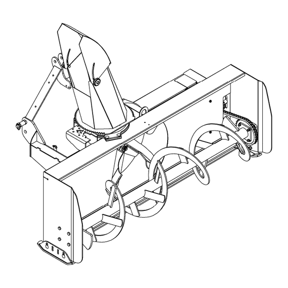
Page 42: Snowblower - B74C
PARTS – B74C NOWBLOWER OM 0410SB-A... - Page 43 PARTS – B74C NOWBLOWER ESCRIPTION Housing (without gearbox) 670790 Chute (including decals) 669782 Knob 657309 Spacer 3/8" thick x 1.25" larg. x 4.5 lg 669178 Spacer 3/16" thick x 1.25" larg. x 4.5 lg 669179 Retaining plate 665935 Carriage bolt 1/2" NC x 1 3/4" gr.5 PTD...
- Page 44 PARTS – B74C NOWBLOWER ESCRIPTION Coupling link #60 654839 Spacer ring .656"ID x 1.760 x 1" ext. 668093 Idler sprocket 60A12 3300022 Spacer ring .656"ID x .807 x 1" ext. 667777 Carriage bolt 5/16" NC x 1" gr.5 PTD 0300003 Carriage bolt 1/2"...
-
Page 45: Gearbox 663485
PARTS 663485 EARBOX ESCRIPTION Casing 659848 Bearing 659844 Shim 656649 Input shaft 664663 Shim 659855 Oil seal 659852 Snap ring 656652 Gear 662236 Parallel key 659850 Output shaft 659853 Bearing 659844 Plug 659847 O-ring 661144 Allen socket head cap screw M8 x 1.25mm x 55mm – 8.8. 0800032 Stover locknut M8 x 1.25mm - 8 0900063... -
Page 46: Driveline 4700159
PARTS 4700159 RIVELINE ESCRIPTION Yoke ass'y 660764 Journal cross 660765 Yoke for female tube 663189 Female tube 4700160 Male tube 4700161 Yoke for male tube 663193 Yoke ass'y 4700058 Bolt M12 x 1.25 x 70 with nut 662199 Grease fitting 663129 Ball Ø1/4"... -
Page 47: Ber0077 - Manual Rotation
PARTS BER0077 - M ANUAL OTATION ESCRIPTION Rotation handle 667425 Rotation tube 660188 Rotation yoke 659595 Universal block 658193 Rotation worm 665953 Rotation worm support 665952 Spring pin 1/4" x 1 1/4" 1600015 Hairpin 4mm x 80mm, PTD 1800002 Plastic handle 656797 Bushing 1 5/16"... -
Page 48: Ber0078 - Hydraulic Rotation
PARTS BER0078 - H YDRAULIC OTATION ESCRIPTION Hydraulic motor 50cc 3910092 - Seal Kit 3910093 Key 1/4" x 1" woodruff (incl. in 3910092) 659191 Motor gear 669705 Flow restrictor 0.052" 664362 Rubber hose 1/4" x 75"lg. 666583 Reducer 1/4"NPT female x 1/2" NPT male 0100040 Male quick coupler 1000006... -
Page 49: Ber0079A - Hydraulic Deflector
PARTS BER0079A - H YDRAULIC EFLECTOR ESCRIPTION Allen socket head capscrews 1/4" x 3/4" PTD 0800050 Lockwasher 1/4" PTD 1200002 Nut hex 1/4" NC PTD 0900001 Carriage bolt 5/16" NC x 3/4" Gr.5 PTD 0300002 654438 Elbow 90° 3/8" NPT STM x 1/4" NPT SWF Deflector bracket 669979 Deflector base bracket... -
Page 50: 8151- Electric Deflector
PARTS 8151- E LECTRIC EFLECTOR ESCRIPTION Actuator 662983 Switchbox 666048 Switch 663383 Rubber cap 658666 Plastic cap 662530 Clevis – rod 666049 Clevis – base 666050 Pin 1" 666057 Ground wire 72" (black) 666054 Tap connector 656665 Fuse wire72" (red) 666055 Actuator wire assembly 666056... -
Page 51: Torque Specification Table
TORQUE SPECIFICATION TABLE ENERAL SPECIFICATION TABLE SE THE FOLLOWING TORQUES WHEN SPECIAL TORQUES ARE NOT GIVEN Note:These values apply fasteners as received from supplier dry, or when lubricated with normal engine oil. They do not apply if special graphited or moly sidulphide greases or other extreme pressure lubricants are used. These values apply to dry conditions;... - Page 52 Manufactured by: RADTECH Division of RAD Technologies Inc. 2835, Chemin de l’Aéroport Thetford Mines, Québec, Canada, G6G 5R7 Tel.: (418) 338-4499 - Fax: (418) 338-6090 e-mail : radtech@radinter.com Internet : www.radinter.com Printed in Canada...
Need help?
Do you have a question about the B74C and is the answer not in the manual?
Questions and answers