
Subscribe to Our Youtube Channel
Related Manuals for Blizzard 680LT


Summary of Contents for Blizzard 680LT
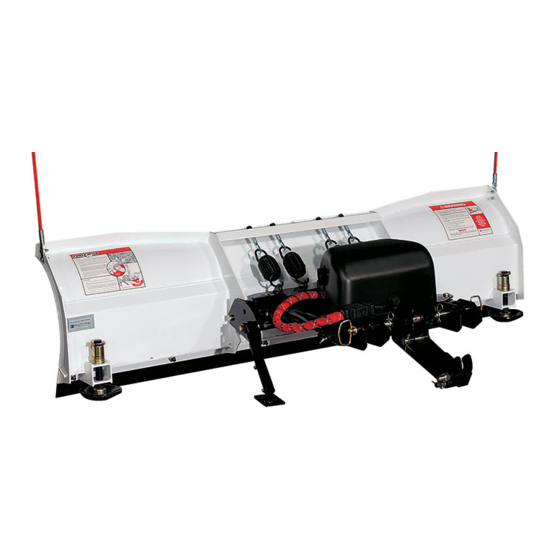
- Page 1 2004 Assembly & Operation Manual Blizzard ® Straight Blade Snowplow Models 680LT & 720LT...
-
Page 2: Table Of Contents
Plow Diagrams & Part Lists an additional 5" of blade that rolls snow Models 680LT & 720LT Parts List farther ahead and to the side when Models 680LT & 720LT Assembly Schematic plowing. Now you can move snow Manifold Detail with Hydraulic &... - Page 3 Paint provided in 12 oz. spray cans. Blizzard hydraulic oil maintains its viscosity to temperatures as low as -60˚F. Blizzard oil is available by the quart, gallon or case. Snowplow Accessories 01...
- Page 4 Calumet, Michigan 49913 Blizzard straight blade snowplows are protected by U.S. Patents 6,178,669; 6,276,076 and 6,393,737. Other patents pending. BLZ 1060 Should the WARNING! label or any of the labels...
-
Page 5: Warning
Snowplow Operation BLIZZARD ® Your snowplow is the most advanced and versatile straight blade on the market. The easy-to-use joystick control allows you to automatically adjust the plow blade into an infinite number of plowing positions. Review the illustrations below for instruction on maneuvering your snowplow. -
Page 6: Assembly Instructions
Assembly Instructions Unpacking & Inspection Your Blizzard straight blade has been packaged to withstand transit and Date of Purchase weather related damage. Fully inspect all components upon receipt of your plow. In the event of shipping damage or missing parts, immediately contact our Customer Service Department toll free at 1-888-680-8600. -
Page 7: Moldboard & A-Frame Assembly
Moldboard & A-Frame Assembly 1. Begin the moldboard assembly by positioning the PIVOT BEAM and A-FRAME near the connecting points at the rear of the blade between 10-1/2" the two center support ribs. Position the pivot beam between the two support ribs until the connecting points on the beam align with those on the plow. - Page 8 6. Begin the draw latch installation by first removing the DRAW LATCH MOUNT PIN, SPACER & COTTER PIN from the assembly. By removing this pin, the INNER DRAW LATCH PLATES can swing free. Proceed to remove the INNER DRAW LATCH PLATE LIFT CYLINDER MOUNT PIN.
- Page 9 Installing The Manifold Adapters 7/16" There are a total of 4 hydraulic adapters to install. All of the adapters can be found packaged with the manifold assembly. Remove the protective stretch wrap from the manifold in a clean area. DO NOT let any foreign objects enter into the open ports.
- Page 10 Secure one 3/8" flat washer, lock washer and 3/8"-16 x 1-1/4" hex Use Loctite On All Manifold head cap screw through the top mount hole in the rear bracket and ® Mount Hardware into the pump. The bottom mount hole receives one 3/8" INTERNAL/ EXTERNAL TOOTH LOCK WASHER, 3/8"...
-
Page 11: Electrical Assembly - Plow Harness
Electrical Assembly - Plow Harness Diode Pack Mount Bracket 1. Begin the electrical assembly by connecting the RED POWER WIRE from the PLOW ELECTRICAL HARNESS to the PUMP motor terminal stud using the hardware provided on the pump. Note: The red power wire contains an end ring terminal too large for the pump motor stud. -
Page 12: Electrical Assembly - Vehicle Harness
Electrical Assembly - Vehicle Harness CAUTION: Always perform the vehicle wire harness assem- bly with the vehicle off and the keys out of the ignition. Use caution when testing the electrical wires for the vehicle’s headlight functions. 1. Begin the installation of the electrical harness under the hood. Insert the WHITE POWER CONNECTOR &... - Page 13 8. Connect the vehicle headlights to the main lighting harness using a HEADLIGHT ADAPTER KIT. Due to differences in the construction of the adapter kits, and the various make and model vehicles Blizzard snowplows are installed on, a headlight adapter kit is not packaged with your snowplow.
-
Page 14: Testing The Snowplow
Pull out and twist each handle to temporarily unlock the pins. Place the light tower into the pockets and relock the pins. See your local Blizzard dealer for com- plete installation instructions for your vehicle undercarriage. - Page 15 Congratulations on a successful assembly and installation! Once all of the blade and electrical functions have been tested your Blizzard straight blade is ready for action. Should you need additional support during a plow assembly or undercarriage installation, contact your local authorized Blizzard dealer.
-
Page 16: Power Hitch™ Instruction
And Hooks Onto Draw Pin BLZ 1059 Should the Mounting & Dismounting Instructions label or any of the labels that came with your snowplow become hard to read or wear off, contact your local authorized Blizzard dealer for replacements. Power Hitch™ Instruction... -
Page 17: Notes
Notes Notes... -
Page 18: Regular Maintenance
(MPGM) is recommended for lubrication. 7. Clean and cover deep scratches or exposed metal with Blizzard Snow- plow white (P/N 61219) or black (P/N 63073) touch-up paint. Contact your local Blizzard Dealer for availability. -
Page 19: Storing Your Snowplow
(MPGM) is recommended for lubrication. 6. Clean and cover deep scratches or exposed metal with Blizzard Snow- plow white (P/N 61219) or black (P/N 63073) touch-up paint. Contact your local Blizzard dealer for availability. -
Page 20: Plow Specifications
Deadheading a plow function will result in Cartridge Valves................5 significantly increased amperage. Relief Valve ..................1 Unless otherwise indicated, all specifications are for the Model 680LT & 720LT straight blade Flow Control Valve ................1 snowplows. Weight ................13.3 lb. -
Page 21: Models 680Lt & 720Lt Parts List
Screw, Hex Head Cap, 5/16"-18 x 1" Grade 5 Z 61052 Nut, Nylon Insert Lock, 5/16"-18 Z 63102 Decal, Passenger’s Side Moldboard (BLZ 1057) - Model 680LT 63110 Decal, Passenger’s Side Moldboard (BLZ 1065) - Model 720LT 63105 Label, WARNING! (BLZ 1060) - Page 22 M O D E L S 6 8 0 LT & 7 2 0 LT PA R T S L I S T Ref. Part Build Quantity Part Description 680LT 720LT Draw Latch Assembly Parts 55A 82087 Draw Latch Assembly: (1) - 30, 56, 58, 59, 61-68, (2) - 55, 60, (3) - 57 82084 Outer Draw Latch Plate Weldment, Driver’s &...
- Page 23 Kit, Hydraulic Hose: (1) - 34, 35, 39, 41 61457 Kit, Hardware, Moldboard Cutting Edge - Models 680LT & 720LT: (6) - 3 & 4 61458 Cutting Edge (with Hardware Kit), Moldboard - Model 680LT: (1) - 2 (81062), 61457...
- Page 25 Blizzard Corporation does not warranty non-Blizzard snowplow service parts or accessories or damage resulting from the use of these unauthorized items. Blizzard snowplows are protected by one or more of the following U.S. patents: 5,638,618; 5,899,007; 6,178,669; 6,276,076; 6,393,737; 6,615,513. Other patents pending.
-
Page 26: Manifold Detail With Hydraulic & Electrical Schematics
RIGHT ANGLE CONNECTS TO PACKARD ELECTRIC CONNECTOR SEE SCHEMATIC ON PAGE 27. LIFT CYL. LEFT ANGLE 3000 PSI RAISE LOWER T1 P1 Manifold Detail w/Hydraulic & Electrical Schematics... - Page 27 WIRE STRIPE BLIZZARD HARNESS PLUG (VEHICLE) COLOR COLOR UNIVERSAL 14 + 2 MOLD (BLUE) (BLACK) COLOR FUNCTION PIN NUMBER BLACK GROUND WIRE STRIPE COLOR COLOR BLACK GROUND BLUE/WHITE (RED) (WHITE) 12 VOLT DC (+) BROWN/WHITE PUMP SOLENOID TO RING BROWN...
- Page 28 Diagram - Plow Harness...
-
Page 29: Plow Harness Wire Schematic
Plow Harness Wire Schematic... - Page 30 Diagram - Main Lighting Harness...
- Page 31 Main Lighting Harness Wire Schematic...
- Page 32 Diagram - Vehicle Harness...
-
Page 33: Vehicle Harness Wire Schematic
Vehicle Harness Wire Schematic... - Page 34 Diagram - On/Off Switch Leads & Ground...
-
Page 35: Torque Specifications
Blizzard Corporation has made an effort to present the above contents accurately, but we do not guarantee its completeness or validity. This information is subject to change at any time, without notice. -
Page 36: Troubleshooting
If the problem is not resolved, replace the harnesses until the pump can be tested or a solenoid. Blizzard dealer can diagnose the problem. Short in the joystick control or wire harness. Disconnect the joystick in the cab. If the solenoid turns off, there is a short in the electrical system. - Page 37 Problem Probable Cause(s) Suggested Remedy Plow will not lift with magnification to the Hydraulic lock in the manifold. This occurs if the voltage is Loosen cartridge valve S6 to relieve pressure and re- S6 coil. too low on the coils – should be 11.8 volts. tighten.
-
Page 38: Limited Consumer Warranty
1. Expendable parts such as cutting edges, plow shoes, hoses, fasteners, blade guides, paint finish, etc. 2. Any snowplow or part thereof which has been repaired or altered by anyone other than an Authorized Blizzard Dealer. 3. Any snowplow or part thereof which has been subject to neglect, misuse, accident, improper installation, maintenance, or storage. -
Page 39: Commercial Warranty
1. Expendable parts such as cutting edges, plow shoes, hoses, fasteners, blade guides, paint finish, etc. 2. Any snowplow or part thereof which has been repaired or altered by anyone other than an Authorized Blizzard Dealer. 3. Any snowplow or part thereof which has been subject to neglect, misuse, accident, improper installation, maintenance, or storage. - Page 40 95 Airpark Boulevard Calumet, MI 49913 [888] 680-8600 Blizzard, Power Hitch and Seat Cinch are trademarks of Blizzard Corporation. Blizzard is registered [906] 482-5555 in the United States Patent and Trademark Office. Loctite and 242 are registered trademarks of Loctite Corporation, USA.
Need help?
Do you have a question about the 680LT and is the answer not in the manual?
Questions and answers