Fujitsu ARTG36LHTB Service Manual
Hide thumbs
Also See for ARTG36LHTB:
- Service instruction (102 pages) ,
- Operating manual (40 pages) ,
- Service manual (30 pages)
Table of Contents
Advertisement
Quick Links
SPLIT TYPE
AIR CONDITIONER
DUCT TYPE (50Hz)
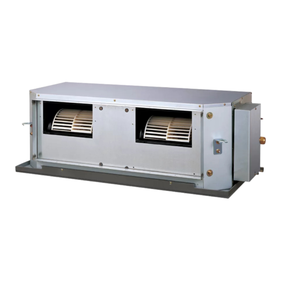
Indoor unit
ARTG36LHTB
CONTENTS
SPECIFICATIONS . . . . . . . . . . . . . . . . . .
DIMENSIONS . . . . . . . . . . . . . . . . . . . . .
REFRIGERANT SYSTEM DIAGRAM . . .
CIRCUIT DIAGRAM . . . . . . . . . . . . . . . . .
INDOOR PCB CIRCUIT DIAGRAM . . . . .
OUTDOOR PCB CIRCUIT DIAGRAM
ERROR DETECTION . . . . . . . . . . . . . . .
PARTS (INDOOR UNIT) . . . . . . . . . . . .
PARTS (OUTDOOR UNIT) . . . . . . . . . .
ACCESSORIES . . . . . . . . . . . . . . . . . . .
Outdoor unit
AOTG36LATT
1
2
4
5
6
10
. .
18
22
25
28
Advertisement
Chapters
Table of Contents
Troubleshooting

Related Manuals for Fujitsu ARTG36LHTB


Summary of Contents for Fujitsu ARTG36LHTB
-
Page 1: Air Conditioner
AIR CONDITIONER DUCT TYPE (50Hz) Indoor unit Outdoor unit ARTG36LHTB AOTG36LATT CONTENTS SPECIFICATIONS ....DIMENSIONS ..... - Page 2 SPECIFICATIONS ELECTRICAL DATA NOISE LEVEL Cooling & Heating TYPE High 41 dB INDOOR UNIT ARTG36LHTB INDOOR UNIT Medium 38 dB OUTDOOR UNIT AOTG36LATT 36 dB COOLING CAPACITY 10.5 kW Cooling 51 dB OUTDOOR UNIT HEATING CAPACITY 12.1 kW Heating 53 dB...
- Page 3 DIMENSIONS INDOOR UNIT (Unit : mm) 1,080 1,000 1,050 Drain hose diameter Inside : 23.4 mm Outside : 25.4 mm 2010.12.09...
- Page 4 OUTDOOR UNIT (unit : mm) air flow 2008.11.20...
-
Page 5: Refrigerant System Diagram
REFRIGERANT SYSTEM DIAGRAM OUTDOOR UNIT INDOOR UNIT Refrigerant flow Refrigerant Pipe Cool Pressure 15.88mm (5/8") Check Valve Heat Strainer 3-Way Valve 4-way Valve Pressure Sensor Heat Heat Exchanger Exchanger Muffler Accumulator Compressor Refrigerant Pipe Expansion 9.52mm (3/8") Valve Strainer Strainer Thermistor (Compressor) 3-Way Valve Thermistor (Room) - Page 6 OUTDOOR UNIT CIRCUIT DIAGRAM OPTION ( CONNECTION ) INDOOR UNIT REFER TO THE TECHNICAL MANUAL GRAY THERMISTOR GRAY ( PIPE TEMP. ) BLACK THERMISTOR BLACK ( ROOM TEMP. ) 1 2 3 1 2 3 1 2 3 1 2 3 1 2 3 1 2 3 4 5 6 1 2 3 4 5 6...
- Page 7 INDOOR PCB CIRCUIT DIAGRAM CN8-1 BLACK THERMISTOR ( ROOM TEMP. ) B02B-XASK-1-A CN8-2 BLACK WHITE CONTROL UNIT CN7-1 B02B-XAYK-1-A CN7-2 EZ-0112KHSE YELLOW CN5-1 GRAY THERMISTOR ( PIPE TEMP. ) B02B-XAKK-1-A CN5-2 GRAY CN2-1 BLACK CN2-2 TEST CN2-3 CN2-4 CN2-5 RECEIVER UNIT ( OPTION ) TERMINAL HP-T3031-3-L1 BLACK...
- Page 8 INDOOR UNIT MAIN PCB K06AK-110PHSE-C1 R1 - R3 B02B-XASK-1-A 1SS355 10k <1/10W> x 3 THERMISTOR ( ROOM TEMP. ) I C8 FLOAT SWITCH 13.5V NJM7812 B03B-PASK-1 <1/10W> B02B-XAYK-1-A 1.0k B03B-XARK-1-A <F> <1/10W> <1/10W> DC SUPPLY 1.0k 49.9k 0.01 1.0k B02B-XAKK-1-A <F>...
- Page 9 NORMAL COIL CN108 B2P3-VH-B R103 340V D108 13.5V D2FL20U <RS-2W> T101 C108 ZFT22B03-C 4700p C113 R111 <FNS> I C26-14 1000/ R104 <1/10W> 330k <2W> D102 1SR139-600 F101 C114 0.01 C109 250V <KH> 220p D107 Q101 D106 RD16 D101 <B> 2SC5354 D1FL20U E103 LF101...
- Page 10 INDOOR UNIT INDICATOR PCB ( OPTION ) K04EI-1000HSE-D0 R201 330 <1/4W> D205 EMPG3863X GREEN R202 330 CN201 <1/4W> D206 EMAA3863X ORANGE 08 / 08 JC25 / XMR R203 330 ( OPERATE ) <1/4W> BROWN D207 EMPG3863X GREEN ( TIMER ) ( LOUVER ) ORANGE ( LOUVER )
- Page 11 OUTDOOR PCB CIRCUIT DIAGRAM INVERTER ASSEMBLY THERMISTOR REACTOR REACTOR REACTOR ( HEATSINK TEMP. ) EZ-01120HUE 12A 18mH UL1007 UL1007 AWG24 AWG24 WHITE BLACK FLASH UL1015 UL1015 UL1015 UL1015 UL1015 UL1015 AWG14 AWG14 AWG14 AWG14 AWG14 AWG14 WHITE WHITE BLACK BLACK TM300 TM500 TM301 TM501 TM302 TM502...
- Page 12 OUTDOOR UNIT MAIN PCB K11BU-1100HUE-C1 CN14 340V P I N101 P I N102 5V R59, R58, R57 B6 ( 7-3 ) B-XN I RK-B-2 12V-2 R101 I PS-1124 I PS-1124 10k <1/10W> x 3 REACTOR CN101 ZPR0RCH400 R77 - R79 D101 D151 CN102...
- Page 13 OUTDOOR UNIT ACTIVE FILTER PCB - 1 K11BZ-1100HUE-AF0 REACTOR L1 - L3 12A 18mH From Filter PCB TM504 TM300 TM500 DC+ OUT L1 I N W300 TM301 TM501 L2 I N W301 TM302 TM502 L3 I N W302 TM505 N OUT CT301, CT300 D351 FC-1-X x 2...
- Page 14 OUTDOOR UNIT ACTIVE FILTER PCB - 2 K11BZ-1100HUE-AF0 Jump To Page1 Jump To Page1 R530, R536 47k 1% x 2 D530 I C510-3 D470 R539 R590 C530 RB751V BA2901F DAN217U D533 R533 RB751V <F> R470 - R474 R503 8.2k 1% C591 220k <1/3W>...
- Page 15 OUTDOOR UNIT TRANSISTOR PCB K11CA-1200HUE-TR1 TM802 YELLOW P I N D908 US1J TM803 BLUE R900 R901 R902 N I N <2.8W> P I N801 <7W> <7W> L960 RGDU7M RGGS7 RGGS7 BL02Rn1 R940 - R949 DC + P I N800 0.1 <1W> 1% x 10 L900 BL02Rn1 K880...
- Page 16 OUTDOOR UNIT FILTER PCB K07AQ-0700HUE-FL0 3 Phase 380 - 415V 50Hz VA202 L200 L201 H-0017-2 x 2 820V RC3V3812-009PF05 RC3V3812-009PF05 FH200 FH201 L1 I N <TNR> 12A 0.9mH 12A 0.9mH TM203 L1 OUT TM200 VA200 P200 <NSHV4> 820V <TNR> H-0017-2 x 2 L2 I N FH202 FH203...
- Page 17 OUTDOOR UNIT CAPACITOR PCB K07AP-0700HUE-P0 W700 W702 P OUT P I N YELLOW ORANGE R700 R702 C700 C702 660/ 660/ 450V <RS-5W> <RS-5W> 450V R701 R703 C701 C703 660/ 660/ <RS-5W> <RS-5W> 450V 450V W701 W703 N OUT N I N BLUE PURPLE 2012.04.13...
- Page 18 OUTDOOR UNIT COMMUNICATION PCB ( OPTION ) K10BQ-1200HUE-CA0 I C1 PS2561L-1-V 4.7k 0.01 <1/4W> <B> <B> R5, R4, R3, R2 TO SMART METER TO MAIN PCB 390 <1/4W> x 4 0.01 I C2 <B> PTZ24B PS2561L-1-V 4.7k ML-41-S1BYF-4P <1/4W> 0.01 B6 ( 7-3 ) B-XN I RK-B-2 <B>...
-
Page 19: Wired Remote Control
ER R OR D ETEC TION WIRED REMOTE CONTROL This is possible only on a wired remote control. If an error occurs, the following display will be shown. (“Er” will appear in the set room temperature display.) Error code Unit number of indoor unit : 0.5s on / 0.5s off : 0.1s on / 0.1s off... -
Page 20: Test Run Method
OUTDOOR UNIT TEST RUN CAUTION Always turn on the power 6 hours prior to the start of the operation in order to protect the compressor. 1. Check items before performing the test run 2.1. Operating procedures for the test run Make sure to perform the test run. -
Page 21: Error Code Check Table
OUTDOOR UNIT ERROR CODE DISPLAY Display when an error occurs TEST PUMP POWER LOW NOISE PEAK CUT DOWN ERROR MODE (L1) (L2) (L3) (L4) (L5) (L6) (L7) Blinks (Hi-speed) Check that the ERROR LED blinks, and then short-press the [ENTER] switch once. Display mode : ON The number of blinks of the LED indicates the type of error. -
Page 22: Pump Down Procedure
2. Pump down procedure OUTDOOR UNIT PUMP DOWN (Refrigerant collecting operation) (1) Check the 3-way valves (both at the liquid side and gas side) are opened. (2) Turn the power on. Perform the following procedures to collect the refrigerant when moving the indoor unit or outdoor unit TEST PUMP POWER... - Page 23 PARTS INDOOR UNIT Ref. Description Parts number Plate Top Sub Assy 9372576014 Connector : white black Kit (Panel Front Sub Assy) 9372637029 Kit (Panel Rear Sub Assy) 9372636022 Room Thermistor 9703299216 Evaporator Sub Assy 9372584033 Pipe Thermistor 9703297113 Drain Pan Assy 9372579015 Kit (Panel Right Sub Assy) 9372916032...
- Page 24 INDOOR UNIT Ref. Description Parts number Panel Fan Assy 9372035009 Bracket Motor Assy 9372037010 Motor Mount Assy 9380216001 Motor Band Assy 9378033016 Motor Band 9378031012 RFM Motor Band 9378003019 Motor, DC Brushless 9603086015 Casing A 9372057018 Casing B 9372058015 Sirocco Fan 9372059029 2012.06.13...
- Page 25 INDOOR UNIT Ref. Description Parts number Control Box Assy 9374854035 Power Supply PCB 9707398397 Main PCB 9709245095 Reactor 9707457018 Terminal 3P 9703345012 Terminal 3P 9306489045 Remote Control 9318593020 2012.06.13...
- Page 26 PARTS OUTDOOR UNIT Ref. Description Parts number Ref. Description Parts number Top Panel Sub Assy 9374417032 Reactor Assy 9900641016 Front Panel Sub Assy 9374414130 Motor, DC Brushless 9602843046 Sevice Panel Sub Assy 9374415076 Propeller Fan Assy 9366378020 Emblem Rear 9351355005 Condenser A Sub Assy 9374420261 Pipe Cover Front...
- Page 27 OUTDOOR UNIT 4-way Valve Assy Ref. Description Parts number Expansion Valve Coil 9900190057 Expansion Valve Assy 9370947182 Strainer Assy 9372524039 Solenoid 9970113024 4-way Valve Assy 9374425273 3-way Valve Assy 9379079006 3-way Valve Assy 9379077002 Sensor 9900505011 Accumulator Assy 9375250096 Expansion Valve Assy Compressor Sub Assy 9374423286 2012.03.16...
- Page 28 OUTDOOR UNIT (yellow) (white) (red) (white) (connector : blue) Ref. Description Parts number Main PCB 9709249017 Filter PCB 9707609011 Active Filter PCB 9709008010 Capacitor PCB 9707608014 Transistor PCB 9709010020 Reactor Assy 9900481018 (red) Terminal 9900428082 Compressor Thermistor 9900516000 Discharge Thermistor 9900515003 (red) Thermistor (Heat Exchanger Mid)
- Page 29 A C C ESSOR IES INDOOR UNIT OPTIONAL PARTS Name and Shape Q'ty Application Part number Parts name Model No. Application Wired UTY-RNNYM For air conditioner operation Special nut A 313005446653 remote control (large flange) For suspending the indoor unit from ceiling Special nut B Simple UTY-RSNYM...
- Page 30 1204G4067...
-
Page 31: Table Of Contents
SPLIT TYPE ROOM AIR CONDITIONER WALL MOUNTED TYPE Indoor unit Outdoor unit ASTG09LVCC AOTG09LVCC ASTG12LVCC AOTG12LVCC CONTENTS SPECIFICATIONS....DIMENSIONS ..... . REFRIGERANT SYSTEM DIAGRAM. -
Page 32: Specifications
SPECIFICATIONS ELECTRICAL DATA NOISE LEVEL High 41 dB 42 dB Cool & heat inverter TYPE INDOOR UNIT ASTG09LVCC ASTG12LVCB Medium 36 dB 37 dB INDOOR UNIT Cooling AOTG09LVCC AOTG12LVCB 30 dB 30 dB OUTDOOR UNIT 3.50 kW Quiet 21 dB 21 dB COOLING CAPACITY 2.50 kW... -
Page 33: Dimensions
DIMENSIONS Unit : mm INDOOR UNIT Drain hose Diameter Outside Inside : 13.8 mm 2012.05.29... - Page 34 Unit : mm OUTDOOR UNIT AOTG09LVCC AOTG12LVCC 2012.05.29...
-
Page 35: Refrigerant System Diagram
REFRIGERANT SYSTEM DIAGRAM Heat exchanger (indoor unit) Refrigerant pipe diameter Liquid : 1/4" (6.35 mm) 2-Way valve Gas : 3/8" (9.52 mm) 3-Way valve Compressor Refrigerant direction Muffler Cooling Heating Strainer 4-Way valve Expansion valve Heat exchanger (outdoor unit) Strainer 2012.05.29... -
Page 36: Circuit Diagram
COMMUNICATION PCB ( OPTION ) UTY-TWBXF INDOOR UNIT WHITE INDICATOR PCB EX IN ( OPTION ) CNA01 CN201 WHITE MAIN PCB WHITE TO MAIN PCB CND01 EX OUT ( OPTION ) WHITE ORANGE WHITE CNB01 OPERATION STATUS WHITE YELLOW LOUVER WHITE WHITE PINK... -
Page 37: Indoor Pcb Circuit Diagram
EARTH TERMINAL INDOOR PCB CIRCUIT DIAGRAM OUTDOOR UNIT THERMAL FUSE 102 EMI FILTER CONTROL UNIT ASTG09LVCC : EZ-012THSE TERMINAL ASTG12LVCC : EZ-012WHSE 2013485-1 B5 ( 6-5 ) B-XARK B04B-PL I SK-1 BLACK THERMISTOR ( PIPE TEMP. ) BLACK BLACK BLACK FAN MOTOR THERMISTOR ( ROOM TEMP. - Page 38 TP00351-31 x 2 INDOOR UNIT D1FL20U 3.15A 2013485-1 340V MAIN PCB 250V SS21V 0.6A - 10mH BLACK S1NBC60 ASTG09LVCC : K10BN-1200HSE-C1 100/ 100k WHITE TERMINAL <1/10W> 0.01 2200p ASTG12LVCC : K10BN-1201HSE-C1 <F> <1/2W> <E> 470V <TND10V> <LE> 0.01 D1FL20U <F> EE16 5V-2 330/...
- Page 39 INDOOR UNIT INDICATOR PCB K09CB-0900HSD-D0 CN201 8-JB / PL I L250 #26 / 1061 D201 SLR-343MC GREEN D202 SLR-343DC ORANGE D203 SLR-343MC GREEN TO MAIN PCB SW201 KSHC611BT D204 SLR-343MC GREEN R202 I C201 GP1UM261R <1/4W> C202 C203 <F> 2012.05.12...
- Page 40 CND01 390V T301 D303 JM303 SJH20-09WSF RF101L2S SW1614-1 R301 C302 390k 1000p C306 R309 <1/4W> <E> TO MAIN PCB 100/ R302 <1/10W> <1/4W> D301 UF4007 + C301 D302 RF101L2S 450V R306 I C301 1.0k LNK603 R303 R304 C311 <1/10W> 100/ BP_M C305 R305...
-
Page 41: Outdoor Pcb Circuit Diagram
OUTDOOR PCB CIRCUIT DIAGRAM INVERTER ASSEMBLY AOTG09LVCC : EZ-0126HUE AOTG12LVCC : EZ-0127HUE REACTOR EMI FILTER TERMINAL EMI FILTER EMI FILTER 13mH, 8A UL3271 ZCAT2132-1130 ZCAT3035-1330 TO INDOOR UNIT AWG16 UL1015 UL3271 AWG20 AWG16 W101 BLACK WHITE UL3271 UL1015 AWG16 AWG20 BLACK W102 WHITE... - Page 42 OUTDOOR UNIT, MAIN PCB AOTG09LVCC : K10BO-1206HUE-C1 AOTG12LVCC : K10BO-1207HUE-C1 C100 : AOTG12LVCC only F100 POWER SOURCE REACTOR R401 - R410 AC240V W101 250V 0.1 <3/4W> 1% 50Hz D102 x 10 L300 C4, C5 UF4007 C201 C200 FH100 FH101 DCV-F D100, D101 47uH H-0017-2 x 2...
- Page 43 UTY-XCZZ2 (OPTION) DEMAND CONTROL OPTION PCB K12GV-1200HUE-CA0 I C1 0.01 PS2561L-1-V <B> R5, R4, R3, R2 4.7k 0.01 390 <1/4W> <1/4W> <B> B6 ( 7-3 ) B-XN I RK-B-2 I C2 0.01 <B> PS2561L-1-V <B> PTZ24B HP-T5338-1-4P R10, R9, R8, R7 TO MAIN PCB 4.7k 0.01...
-
Page 44: Error Detection
ER R OR D ETEC TION Indoor unit LED Indoor unit LED Wired Wired Description Description remote remote OPERATION TIMER ECONOMY OPERATION TIMER ECONOMY control control (green) (orange) (green) (green) (orange) (green) INDOOR UNIT Display PCB microcomputers Serial communication error and WIRED REMOTE CONTROL (10) communication error... - Page 45 OUTDOOR UNIT ERROR Discharge temperature error 5.0 second on / 5.0 second off Fan motor error 2.0 second on / 2.0 second off CT error 1.0 second on / 1.0 second off Timer contraction 0.5 second on / 0.5 second off IPM overcurrent protection 0.1 second on / 0.1 second off Thermistor error...
- Page 46 If the air conditioner is under demand controlling, consult on the issues with your electricity supplier. If they are not demand controlling the air conditioner, refer to your warranty card for the contact details of Fujitsu General (AUST.) PTY LIMITED or visit our website : www.fujitsugeneral.com.au 2012.05.17...
-
Page 47: Parts (Indoor Unit)
PARTS PARTS INDOOR UNIT Description Parts number Front Panel Total Assy 9318423037 Front Panel 9318200027 Intake Grille Assy 9318424027 Grille Clamper 9316906006 Air Filter 9318202007 Receiver Window 9318201000 Panel Cover 9318203004 Wire Cover 9318234008 Wire Shield 9318235005 Louver Upper 9318224009 Louver Lower 9318225006 Room Thermistor Holder... - Page 48 INDOOR UNIT Description Parts number Control Box 9318228007 Box Shield Assy 9318387001 Cover Shield 9318230000 Main PCB (09) 9708673110 Main PCB (12) 9708673127 Terminal 9900638009 Earth Terminal 9318231014 Gear Cover 9318211016 Step Motor 9900139179 Panel Gear 9316653009 Gear A 9309994003 Display Case 9318232004 Display PCB...
- Page 49 INDOOR UNIT Description Part number Evaporator Total Assy 9318397000 Joint Pipe Assy 9318400007 Filter Guide 9318223002 Rear Bracket 9318221008 Evaporator Holder R 9318220001 Evaporator Holder L 9318219005 Water Seal B 9318420005 2012.05.29...
- Page 50 INDOOR UNIT Description Part number Fan Motor 9602783038 Crossflow Fan Assy 9315024039 Bearing C Assy 9306628017 Casing Assy 9318392029 2012.05.29...
- Page 51 INDOOR UNIT Casing assy Description Parts number Casing 9318212013 Fan Guard 9318646009 Motor Cover 9316568006 Motor Cover 9316601000 Cable Guide 9316567009 Casing Cover U 9318213003 Casing Cover B 9318214017 Casing Cover F 9318215007 R and L Louver 9318216004 Drain Hose Assy 9316904019 Drain Cap 9316177017...
- Page 52 PARTS OUTDOOR UNIT AOTG09LVCC Ref. Description Part number Protective Net 9331262033 Top Panel Assy 9317939027 Front Panel Assy 9317789028 Cabinet Left Assy 9317813006 Cabinet Right Assy 9317788021 Grip 9317588003 Switch Cover A 9317795005 Switch Cover B 9317582001 Valve Bracket 9316523012 Motor Bracket Assy 9332289039 Fan Motor...
- Page 53 OUTDOOR UNIT AOTG09LVCC Ref. Description Part number Base Assy 9316916029 Condenser Total Assy 9317367172 Compressor Assy 9317083034 2 way Valve Assy 9318252002 3 way Valve Sub Assy 9317366038 4 way Valve Assy 9317890021 Solenoid 9970079023 Pulse Motor Valve Assy 9317216036 Expansion Valve Coil 9970103025 2012.05.29...
- Page 54 OUTDOOR UNIT AOTG09LVCC Ref. Description Part number Sealed Panel 9318181012 Main PCB 9708682204 PCB Holder 9318182019 Inverter Case Assy 9332247015 Terminal Bracket 9317816052 Terminal 9900435028 Heat Sink 9319070001 Outdoor Thermistor 9900565008 Thermistor Assy 9900628000 2012.05.29...
- Page 55 OUTDOOR UNIT AOTG12LVCC Ref. Description Part number Front Panel Assy 9317760041 Emblem 9319151007 Cabinet Left 9318247008 Top Panel Assy 9317761055 Protective Net 9313941055 Switch Cover A Assy 9317795005 Switch Cover B 9317582001 Grip 9317588003 Cabinet Right Assy 9317759021 Valve Bracket 9331649001 Separator Assy 9318340013...
- Page 56 OUTDOOR UNIT AOTG12LVCC Ref. Description Part number Condenser Total Assy 9332359015 Compressor Assy 9317619004 2 way Valve Assy 9332371000 3 way Valve Sub Assy 9317109000 4 way Valve Assy 9332365009 Solenoid 9970110023 Pulse Motor Valve Assy 9332368048 Expansion Valve Coil 9970095030 2012.05.29...
- Page 57 OUTDOOR UNIT AOTG12LVCC Ref. Description Part number Sealed Panel 9318181005 Main PCB 9708682211 PCB Holder 9318182019 Inverter Case Assy 9318242010 Terminal Bracket 9317603034 Terminal 9900435028 Outdoor Thermistor 9900565008 Thermistor Assy 9900628000 Heat Sink 9319070001 2012.05.29...
-
Page 58: Accessories
ACCESSORIES Refer to each installation manual for the method of installing optional parts. INDOOR UNIT Name and Shape Q’ty Parts number Parts name Model No. For air conditioner Bracket panel Wired remote control * UTY-RNNYN operation For air conditioner Simple remote control * UTY-RSNYN 9318236019 operation For control input/output... - Page 59 "Demand response" for outdoor unit Parts list for demand control option PCB kit (optional parts) Parts name Q'ty Demand control option PCB, Option PCB holder Connector cable For connecting the demand control option PCB Cable ties with clips For fixing the signal transmission cable Cable ties For fixing the earth(ground) cable and the 4-way valve lead wire (09LVCC)
- Page 60 1205G4083...
- Page 61 SPLIT TYPE ROOM AIR CONDITIONER WALL MOUNTED TYPE Indoor unit Outdoor unit ASTG18KMCA AOTG18KMCA ASTG22KMCA AOTG22KMCA ASTG24KMCA AOTG24KMCA CONTENTS SPECIFICATIONS....DIMENSIONS ..... . REFRIGERANT SYSTEM DIAGRAM.
-
Page 62: Specifications
SPECIFICATIONS FAN MOTOR ELECTRICAL DATA COMPRESSOR AND REFRIGERANT Cool & heat inverter TYPE POWER SOURCE 240 V Hermetic type, 6 pole, 3 phase, DC inverter motor, COMPRESSOR TYPE INDOOR UNIT ASTG18KMCA ASTG22KMCA ASTG24KMCA Powerful 1,370 r.p.m. 1,450 r.p.m. 1,530 r.p.m. 2-cylinder Rotary OUTDOOR UNIT AOTG18KMCA... -
Page 63: Dimensions
DIMENSIONS INDOOR UNIT 940 mm 270 mm Drain hose Diameter 600 mm Outside 15.8 to 16.7 mm Inside : 13.8 mm OUTDOOR UNIT 290 mm 790 mm 540 mm 2013.08.30... -
Page 64: Refrigerant System Diagram
REFRIGERANT SYSTEM DIAGRAM Heat exchanger (indoor unit) Refrigerant direction Muffler Cooling Heating 2-Way valve Pressure SW 3-Way valve Refrigerant pipe diameter Liquid : 1/4" (6.35 mm) Gas : 1/2" (12.7 mm) Muffler Strainer Compressor 4-Way valve Expansion valve Heat exchanger (outdoor unit) Strainer Sub-accumulator... -
Page 65: Circuit Diagram
Remote control Communication PCB (Option) (Option) 1 2 3 4 5 Ex out (Option) CNC01 CIRCUIT DIAGRAM Error status CNB02 Ex out (Option) CNB01 To main PCB Operation status CND01 Ex in (Option) CNA01 INDOOR UNIT Louver Orange (Left / Right) Yellow Pink CN201... -
Page 66: Indoor Pcb Circuit Diagram
EARTH TERMINAL INDOOR PCB TERMINAL OUTDOOR UNIT CIRCUIT DIAGRAM CONTROL UNIT ASTG18KMCA : EZ-013CHSE ASTG22KMCA : EZ-013DHSE ASTG24KMCA : EZ-013EHSE THERMISTOR ( PIPE TEMP. ) BLACK BLACK B04B-PL I RK-1 BLACK THERMISTOR 2013485-1 BLACK ( ROOM TEMP. ) ORANGE LOUVER CN10 YELLOW B05B-PL I SK-1... - Page 67 3.15A 2013485-1 20*20*18 250V 340V SS21V 0.6A - 10mH 100k BLACK D1FL20U <1/10W> INDOOR UNIT S1NBC60 WHITE 4700p <KY> MAIN PCB 100/ 470V TO TERMINAL <ERZV> <LE> D1FL20U ASTG18KMCA : K13RA-1302HSE-C1 4700p ST03D-140 <KY> + C4 TEE16 ASTG22KMCA : K13RA-1303HSE-C1 420V 330/ BLM18...
- Page 68 INDOOR UNIT INDICATOR PCB K12JZ-1200HSE-D0 D201 SL I-343 CN201 GREEN D202 SL I-343 S7B-PH-K-S ORANGE D203 SL I-343 GREEN SW201 KSHC611BT I C201 R202 GP1UM261R <1/4W> + C202 C203 <B> 2013.06.27...
- Page 69 390V CN301 T301 D303 JM303 SJH20-09WSF SW1614-1 RF101L2S R301 C302 390k 1000p R309 C306 <1/4W> <E> 100/ TO MAIN PCB R302 <1/10W> <1/4W> D301 UF4007 + C301 D302 RF101L2S 450V R306 I C301 1.0k LNK603 R303 R304 C311 <1/10W> 100/ BP_M C305 R305...
-
Page 70: Outdoor Pcb Circuit Diagram
OUTDOOR PCB CIRCUIT DIAGRAM INVERTER ASSEMBLY AOTG18KMCA : EZ-013BHUE AOTG22KMCA : EZ-013CHUE AOTG24KMCA : EZ-013DHUE TERMINAL TO INDOOR UNIT EMI FILTER EMI FILTER EMI FILTER COMPRESSOR UL3271 AWG16 UL1015 AWG18 W101 BLACK UL3271 AWG16 WHITE UL1015 AWG18 W102 WHITE UL3271 AWG16 BLACK SERIAL UL1015 AWG20... - Page 71 OUTDOOR UNIT MAIN PCB AOTG18KMCA : K11BS-1301HUE-C1 AOTG22KMCA : K11BS-1302HUE-C1 F100 D101 AOTG24KMCA : K11BS-1303HUE-C1 L101 AL50201574 RFUS20TF6S 250V C100, C101 W101 C201 C200 L102 D102 600 / 450V 0.22 AL50201574 RFUS20TF6S <F> JM106 ZPR0RCH400 C400 Q404 Q402 2SC2411K C203 C202 C402 <B>...
-
Page 72: Error Detection
ER R OR D ETEC TION INDOOR UNIT REMOTE CONTROL If you use a wireless remote control, the lamp on the photo detector unit will output error codes by way of blinking patterns. OPERATION indicator lamp (green) If you use a wired remote control, error codes TIMER indicator lamp (orange) will appear on the remote control display. - Page 73 OUTDOOR UNIT ERROR Discharge temperature error 5.0 second on / 5.0 second off Fan motor error 2.0 second on / 2.0 second off CT error 1.0 second on / 1.0 second off Timer contraction 0.5 second on / 0.5 second off IPM overcurrent protection 0.1 second on / 0.1 second off Thermistor error...
- Page 74 If the air conditioner is under demand controlling, consult on the issues with your electricity supplier. If they are not demand controlling the air conditioner, refer to your warranty card for the contact details of Fujitsu General (AUST.) PTY LIMITED or visit our website : www.fujitsugeneral.com.au 2012.05.17...
-
Page 75: Parts (Indoor Unit)
PARTS Ref. Description Part number Remote Control 9320360023 INDOOR UNIT Remote Control Holder 9318912005 Electric Filter Holder 9332911008 Air Clean Filter Assy 9317250009 Air Filter 9380997009 Front Panel Sub Assy 9320459000 Intake Grille with logotype 933305200 Wire Cover 9318786002 Wire shield Louver 9318849028 Diffuser Assy... - Page 76 INDOOR UNIT Cover shield Control box Ref. Description Part number Control Cover 9318757002 Control Box 9380996002 Main PCB (18KMCA) 9709622032 Main PCB (22KMCA) 9709622049 Main PCB (24KMCA) 9709622056 Terminal 9900720025 Display Assy 9709642023 Room Thermistor Holder 9379930000 Thermistor Assy 9900627003 2013.09.02...
- Page 77 INDOOR UNIT Evaporator Ref. Description Part number Evaporator Total Assy 9319254098 Fan Motor 9603253011 Crossflow Fan Assy 9315024060 Bearing C Assy 9306628017 Motor Cover 9316568006 Motor Cover 9316601000 Casing Total Assy 9319171180 2013.09.02...
- Page 78 INDOOR UNIT Casing total assy Ref. Description Part number Outlet Cover Assy 9319776002 Motor Case Assy 9319173085 Casing Assy 9319172101 2013.08.20...
- Page 79 INDOOR UNIT Motor case assy Ref. Description Part number Motor Case 9318746020 Gear A 9309994003 Step Motor (R&L) 9900139186 Louver Link Holder 9319150000 Link A 9317507004 Step Motor (Louver) 9900384135 Gear Cover A 9318748000 Louver Gear A 9318749007 Step Motor (Diffuser) 9900384142 Gear Cover B 9318750003...
- Page 80 INDOOR UNIT Casing assy Ref. Description Part number Casing 9318840018 Casing Cover F 9318864007 Casing Cover B 9318862003 Casing Cover L 9318830002 Casing Cover R 9318831009 R and L Louver Assy 9319229027 Fan Guard 9320458003 Pipe Bracket 9318743012 Drain Cap 9316177017 Drain Hose Assy 9316904019...
-
Page 81: Parts (Outdoor Unit)
PARTS OUTDOOR UNIT Ref. Description Part number Protective Net 9331640015 Top Panel Assy 9318464139 Front Panel Assy 9320114022 Emblem 9319151007 Cabinet Left Assy 9318461015 Cabinet Right Assy 9318462050 Grip 9317588003 Switch Cover A Assy 9320402006 Switch Cover B 9379206013 Fan Motor 9602724024 Propeller Fan 9320027001... - Page 82 OUTDOOR UNIT Ref. Description Part number PCB Holder 9319547015 Main PCB with grease (18) 9709680070 Main PCB with grease (22) 9709680087 Main PCB with grease (24) 9709680094 Heat Sink 9319540009 Terminal 6P 9900380007 Terminal 4P 9306488116 PCB Holder 9332746006 Communication PCB 9709315040 Outdoor Thermistor 9900565008...
- Page 83 OUTDOOR UNIT Ref. Description Part number Condenser Total Assy 9317089289 Compressor Assy 9810311009 2-way Valve Assy 9320396008 3-way Valve Sub Assy 9317109079 4-way Valve Assy 9320422004 Solenoid 9970110023 Pulse Motor Valve Assy 9320152017 Expansion Valve Coil 9970095030 2013.07.01...
-
Page 84: Accessories
ACCESSORIES INDOOR UNIT OPTIONAL PARTS OUTDOOR UNIT Name and Shape Part number Name and Shape Part number Name and Shape Name and Shape Part number Wired remote control Drain assy 9303029022 Bracket Panel Tapping screw 0700076046 UTY-RVNYN (M4 x 25 mm) 9318861013 Remote Control 9320360023... - Page 85 1307G4239...
-
Page 86: Installation Manual
INSTALLATION MANUAL AIR CONDITIONER Wall Mounted Type PART No. 9320456009 Contents SAFETY PRECAUTIONS ..............1 ABOUT THE PRODUCT..............3 GENERAL SPECIFICATION ............. 4 ELECTRICAL REQUIREMENT ............4 SELECTING THE MOUNTING POSITION ........4 INSTALLATION WORK ..............4 ELECTRICAL WIRING ..............7 FINISHING ..................7 FRONT PANEL REMOVAL AND INSTALLATION ......8 10. TEST RUN ..................8 11. R EMOTE CONTROLLER INSTALLATION ........9 12. OPTIONAL KIT INSTALLATION (OPTION) ........ - Page 87 CAUTION CAUTION 2-2 Work 3-Repairs to sealed components • Prior to beginning work on systems containing flammable refrigerants, safety checks • During repairs to sealed components, all electrical supplies shall be disconnected are necessary to ensure that the risk of ignition is minimized. For repair to the refrig- from the equipment being worked upon prior to any removal of sealed covers, etc. erating system, the precautions in 2-2 to 2-8 shall be complied with prior to conduct- •...
-
Page 88: About The Product
Explanation of symbols displayed on the indoor unit or outdoor unit. CAUTION This symbol shows that this appliance uses a flammable 9-Charging procedures refrigerant. WARNING • In addition to conventional charging procedures, the following requirements shall be If the refrigerant is leaked and exposed to an external igni- followed. tion source, there is a risk of fire. - Ensure that contamination of different refrigerants does not occur when using This symbol shows that the operation manual should be CAUTION charging equipment. -
Page 89: General Specification
2.2. Accessories 3.2. Additional materials required for installation A. Refrigeration (armored) tape The following installation accessories are supplied. Use them as required. B. Insulated staples or clamps for connecting wire (See your local electrical codes.) Name and Shape Q’ty Name and Shape Q’ty C. Putty D. Refrigeration lubricant Operating Manual Cloth tape E. Clamps or saddles to secure refrigerant piping 4. ELECTRICAL REQUIREMENT Installation Manual Tapping screw (This manual) (M4 × 25 mm) The indoor unit is powered from the outdoor unit. Do not power indoor unit from separate... - Page 90 Detection range of the human sensor is as follows. (1) Install the wall hook bracket so that it is correctly positioned horizontally and vertically. If the wall hook bracket is titled, water will drip to the floor. Vertical angle 90° (Side view) Horizontal angle 100° (Top view) (2) Install the wall hook bracket so that it is strong enough to support the weight of the unit. • Fasten the wall hook bracket to the wall with 5 or more screws through the holes near the outer edge of the bracket. • Check that there is no rattle at the wall hook bracket.
- Page 91 Removing the drain hose Installing the drain hose 6.9.2. Bending pipes Remove the screw at the left of Vertically insert the drain hose toward the • The pipes are shaped by your hands. Be careful not to collapse them. drain hose and pull out drain hose. inside, so that the drain fi xture (white) can ac- • Do not bend the pipes in an angle more than 90° curately align with the screw hole around the • W hen pipes are repeatedly bent or stretched, the material will harden, making it diffi cult drain cock.
-
Page 92: Electrical Wiring
Tightening nut [mm (in.)] Tightening torque [N·m] 7.3. How to connect wiring to the terminals 6.35 (1/4) dia. 16 to 18 12.70 (1/2) dia. 49 to 61 Caution when wiring cable To strip off the insulation of a lead wire, always use a special tool such as a wire strip- Step.6 Confirm that the marking on the connection pipe is within 1mm from the per. -
Page 93: Front Panel Removal And Installation
Overlap the insulation (5) The front panel is pulled to the front, raising the upper surface, then the front panel is removed. Connection pipe (heat insulation) Indoor unit pipe (heat insulation) Bind the pipes together Vinyl tape so that there is no gap. Front panel Pipe Wrap with cloth tape Cloth tape Drain hose Seal A is used when the diameter 9.2. Front panel installation of gas pipe is Ø12.70 or more. (1) First, fit the lower part of the front panel, and insert top and bottom hooks. (3 top sides, 2 center) Top hooks... -
Page 94: Remote Controller Installation
INSTALLATION WORK 11. REMOTE CONTROLLER INSTALLATION Check that the indoor unit correctly receives the signal from the remote controller, then 13.1. Accessories (Communication kit) install the remote controller holder. The following installation accessories are supplied. Use them as required. CAUTION Name and Shape Q’ty Description Relay control board For connecting the Do not install the remote controller holder in the following conditions: wired remote control • A ny places exposed in direct sunlight... -
Page 95: Selecting The Remote Controller Signal Code
13.2.4. Installing optional kits 14. SELECTING THE REMOTE CONTROLLER SIGNAL CODE Remote controller cable modification When two or more air conditioners are installed in a room and the remote controller is op- erating an air conditioner other than the one you wish to set, change the signal code of the (1) U se a tool to cut off the terminal on the end of the remote controller cable, and then remove the insulation from the cut end of the cable. remote controller to operate only the air conditioner you wish to set (4 selections possible). - Page 96 Room temperature sensor switching Selecting the Function Number and Setting Value [Cool model] (Only for wireless remote controller) Function Number (1) P ress the TEMP. ( / ) buttons to select the func- When using the Wired remote controller temperature sensor, change the setting to “Both” tion number. (Press the ECONOMY button to switch (01).
-
Page 97: Customer Guidance
16. CUSTOMER GUIDANCE • 2-way valve temp. sensor error ● ● ◊ • 3-way valve temp. sensor error Heat sink temp. sensor error Explain the following to the customer in accordance with the operating manual: ● ● ◊ (1) S tarting and stopping method, operation switching, temperature adjustment, timer, air flow switching, and other remote control unit operations. • Sub-cool Heat Ex. gas inlet (2) A ir filter removal and cleaning, and how to use the air louvers. temp. sensor error ● ●... -
Page 98: Caution
OPERATING MANUAL REFRIGERANT This Air Conditioner contains and operates with refrigerant R32. THIS PRODUCT MUST ONLY BE INSTALLED OR SERVICED Contents BY QUALIFIED PERSONNEL. Refer to Commonwealth, State, Territory and local legislation, regulations, codes, installation & operation manuals, before AIR CONDITIONER the installation, maintenance or service of this product. -
Page 99: Caution
Safety Precautions (continued) WARNING • Do not install the unit in area fi lled with mineral oil such as a • Do not insert your fi ngers or any other objects into outlet factory or area containing a large amount of splashed oil or port, open panel, or intake grille. -
Page 100: Indoor Unit Overview And Operations
AIR CONDITIONER Wall Mounted Type Indoor Unit Overview and Operations Intake grille Before starting operation, make sure that the intake grille has been shut completely. Incomplete closing may have an effect on the proper function or performance of the product. MANUAL AUTO button Use when the remote controller is lost or there is a malfunction. -
Page 101: Remote Controller Overview And Operations
Remote Controller Overview and Operations CAUTION • To prevent malfunction or damage of the remote controller: • If leaking battery fl uid comes in contact with your skin, eyes, or mouth, immediately rinse with plenty of clean water, and - Place remote controller at where will not be exposed to consult your physician. -
Page 102: Reset Button
AIR CONDITIONER Wall Mounted Type Remote Controller Overview and Operations (continued) Signal transmitter 18 CLOCK ADJUST button See page 2 Aim at the signal receiver of the indoor unit properly. Used for adjusting the clock. • Signal transmit indicator on the remote controller display shows 19 SEND button that the signal from the remote controller is being transmitted. -
Page 103: Timer Operation
Timer Operation Note for timer settings: Any interruption of the power supply, such as a blackout or cutting off of a circuit breaker, makes the set internal clock go wrong. In such a case, the TIMER indicator on the indoor unit blinks, and you need to readjust the setting. ON timer or OFF timer WEEKLY timer You can set the ON timer or OFF timer with the following steps. - Page 104 AIR CONDITIONER Wall Mounted Type Timer Operation (continued) To set the WEEKLY timer, fi rst follow steps ①~③ on page 6 for the ON/OFF timer. Select the program number and the day using the SELECT button. Program 1Week Program Monday Program Tuesday Program Sunday...
-
Page 105: Human Sensor (Energy Saving
If the air conditioner is under demand controlling, consult the issues with your electricity supplier. If they are not demand controlling the air conditioner, refer to your warranty card for the contact details of Fujitsu General (AUST.) PTY LIMITED or visit our website : www.fujitsugeneral.com.au OPERATING MANUAL En-8 9320455002_OM_EN.indd 8... -
Page 106: General Informations On Operation
AIR CONDITIONER Wall Mounted Type General Informations on Operation Automatic defrosting operation Heating performance When outdoor temperature is very low with high humidity, frost This air conditioner operates on the heat-pump principle, may form on the outdoor unit during the heating operation, and absorbing heat from air outdoors and transferring that heat it could reduce the operating performance of the product. -
Page 107: Care And Cleaning
Care and Cleaning CAUTION • Before cleaning the indoor unit, be sure to turn it off and all the power supply has been disconnected. • Before starting operation, make sure that the intake grille has been shut completely. Incomplete closing of the intake grille might have an effect on the proper working or performance of the air conditioner. - Page 108 AIR CONDITIONER Wall Mounted Type Care and Cleaning Following 2 types of air cleaning fi lters are used in this product. Replacing the air cleaning fi lter When you replace them, purchase dedicated air cleaning fi lters for this Remove the air fi lter. (Refer to step 1 in “Replacing the air fi lter”.) product.
-
Page 109: Troubleshooting
Troubleshooting WARNING In following events, immediately stop operation of the air conditioner, and disconnect all the power supply by turning off the electrical breaker or disconnecting the power plug. Then consult your dealer or authorized service personnel. As long as the unit is connected to the power supply, it is not insulated from the power supply even if the unit is turned off. •... - Page 110 SPLIT TYPE ROOM AIR CONDITIONER WALL MOUNTED type INVERTER SERVICE INSTRUCTION Models Indoor unit Outdoor unit AOTG18KMCA ASTG18KMCA AOTG22KMCA ASTG22KMCA ASTG24KMCA AOTG24KMCA...
- Page 111 CONTENTS 1. DESCRIPTION OF EACH CONTROL OPERATION 1. COOLING OPERATION....................01-01 2. HEATING OPERATION....................01-02 3. DRY OPERATION......................01-02 4. AUTO CHANGEOVER OPERATION................01-03 5. INDOOR FAN CONTROL....................01-04 6. OUTDOOR FAN CONTROL..................01-07 7. LOUVER CONTROL..................... 01-08 8. COMPRESSOR CONTROL..................01-09 9.
- Page 112 3. APPENDING DATA 3-1 FUNCTION SETTING....................03-01 3-1-1 INDOOR UNIT....................03-01 3-1-2 Procedures to change the Function Setting for wireless RC......03-03 3-2 Thermistor Resistance Values..................03-05 3-2-1 INDOOR UNIT....................03-05 3-2-2 OUTDOOR UNIT....................03-05 4. INSTALLATION WORK 4-1 Installation Work and Servicing Safety................ 04-01 4-2 TOOLS.........................
-
Page 114: Description Of Each Control Operation
WALL MOUNTED type INVERTER 1 . DESCRIPTION OF EACH CONTROL OPERATION... -
Page 115: Cooling Operation
1. COOLING OPERATION 1-1 COOLING CAPACITY CONTROL A sensor (room temperature thermistor) built in the indoor unit body will usually perceive difference or variation between a set temperature and present room temperature, and controls the operation frequency of the compressor. * If the room temperature is 2°C higher than a set temperature, the compressor operation frequency will attain to maximum performance. -
Page 116: Heating Operation
2. HEATING OPERATION 2-1 HEATING CAPACITY CONTROL A sensor (room temperature thermistor) built in the indoor unit body will usually perceive difference or variation between a set temperature and present room temperature, and controls the operation frequency of the compressor. * If the room temperature is lower by 3°C than a set temperature, the compressor operation frequency will attain to maximum performance. -
Page 117: Auto Changeover Operation
4. AUTO CHANGEOVER OPERATION When the air conditioner is set to the AUTO mode by remote control, operation starts in the optimum mode from among the HEATING, COOLING, DRY and MONITORING modes. During operation, the optimum mode is automatically switched in accordance with temperature changes. The temperature can be set between 18°C and 30°C in 1°C steps. -
Page 118: Indoor Fan Control
5. INDOOR FAN CONTROL 1. Fan speed ( Table4 : Indoor Fan Speed ) Speed (rpm) Operation mode Air flow mode ASTG18KMCA ASTG22KMCA ASTG24KMCA Powerful 1370 1450 1530 Heating 1240 1320 1400 1140 1210 1250 1040 1100 1100 Quiet Cool air prevention S-Lo 1370 1450... -
Page 119: Normal Operation
5. HEATING OPERATION Switch the airflow [AUTO], and the indoor fan motor will run according to a room temperature, as shown in Fig.4. On the other hand, if switched in [Hi] ~ [Quiet], the indoor motor will run at a constant airflow of [Heat] operation modes Quiet, Lo, Me, Hi, as shown in Table4. - Page 120 7. MOISTURE RETURN PREVENTION CONTROL (Cooling mode& Dry mode) Switch the airflow [Auto] at cooling mode, and the indoor fan motor will run as shown in Fig.6. ( Fig.6 : Indoor Fan Control ) Compressor Indoor fan Setting air flow Indoor fan (as shown in Table 5) S-Lo...
-
Page 121: Outdoor Fan Control
6. OUTDOOR FAN CONTROL 1. Outdoor Fan Motor Following table shows the type of the outdoor fan motor. The control method is different between AC motor and DC motor. ( Table6 : Type of Motor ) AC Motor DC Motor AOTG18/ 22/ 24KMCA 2. -
Page 122: Louver Control
7. LOUVER CONTROL 1. VERTICAL LOUVER CONTROL (Function Range) Each time the button is pressed, the air direction range will change as follows: Fig.8 -1 : Air Direction Range Types of Air flow Direction Setting: : During Cooling/ Dry/ Heating mode The Remote Controller's display does not change. -
Page 123: Compressor Control
8. COMPRESSOR CONTROL 1. OPEARTION FREQUENCY RANGE The operation frequency of the compressor is different based on the operation mode as shown in the table10. (Table10 : Compressor Operation Frequency Range) Cooling Heating AOTG18KMCA AOTG22KMCA 10rps 99rps 12rps 120rps 16rps 27rps AOTG24KMCA 2. -
Page 124: Timer Operation Control
9. TIMER OPEARTION CONTROL The table11 shows the available timer setting based on the product model. (Table11 : Timer Setting) ON TIMER/ OFF TIMER PROGRAM TIMER SLEEP TIMER WEEKLY TIMER ASTG18/ 22/ 24KMCA 1. OPEARTION FREQUENCY RANGE OFF timer : When the clock reaches the set time, the air conditioner will be turned off. Operation mode Stop mode Set time of timer... - Page 125 3. SLEEP TIMER If the sleep is set, the room temperature is monitored and the operation is stopped automatically. If the operation mode or the set temperature is change after the sleep timer is set, the operation is continued according to the changed setting of the sleep timer from that time ON. In the cooling operation mode When the sleep timer is set, the setting temperature is increased 1°C.
-
Page 126: Electronic Expansion Valve Control
10. ELECTRONIC EXPANSION VALVE CONTROL The most proper opening of the electronic expansion valve is calculated and controlled under the present operating condition based on the Table12. The compressor frequency, the temperatures detected by the discharge temperature sensor, the indoor heat exchanger sensor, the outdoor heat exchanger sensor, and the outdoor temperature sensor. -
Page 127: Manual Auto Operation (Indoor Unit Body Operation)
15. MANUAL AUTO OPERATION (Indoor unit body operation) If MANUAL AUTO Button is set, the operation is controlled as shown in Table13. If the remote control is lost or battery power dissipated, this function will work without the remote control. (Table13) Manual auto operation Forced cooling operation... -
Page 128: Human Sensor
20. HUMAN SENSOR The Human sensor functions by pressing SENSOR button on the remote controller. When the sensor detects that there is no one in the room for 20 minutes or more, it automatically changes the operation as below settings. When someone comes back into the room, the human sensor will detect this, and automatically revert to the original settings. -
Page 129: Defrost Operation Control
23. DEFROST OPERATION CONTROL 1. CONDITION OF STARTING THE DEFROST OPERATION The defrost operation starts when the outdoor heat exchanger temperature sensor (Tn) detects the temperature lower than the values shown in Table19. ( Table 19 : Condition of starting Defrost Operation ) Compressor integrating operation time time defrosting after starting operation... - Page 130 3. Defrost Flow Chart The defrosting shall proceed by the integrating operation time, outdoor temperature and outdoor heat exchanger temperature as follows. Heating operation start : Compressor ON (Not defrosted for 10 minutes) 1st defrost 2nd and later defrost Integrating defrost (Constant monitoring) Compressor Compressor...
-
Page 131: Off Defrost Operation Control
24. OFF DEFROST OPEARTION CONTROL When operation stops in the [Heating operation] mode, if frost is adhered to the outdoor unit heat exchanger, the defrost operation will proceed automatically. In this time, if indoor unit operation lamp flashes slowly (7 sec ON / 2 sec OFF), the outdoor unit will allow the heat exchanger to defrost, and then stop. -
Page 132: Various Protections
25. VARIOUS PROTECTIONS 1. DISCHARGE GAS TEMPERATURE OVERRISE PREVENSION CONTROL The discharge gas thermosensor (discharge thermistor : Outdoor side) will detect discharge gas temperature. When the discharge temperature becomes higher than Temperature ,the compressor frequency is decreased 20rps, and it continues to decrease the frequency for 20rps every 120 seconds until the temperature becomes lower than Temperature . - Page 133 3. ANTIFREEZING CONTROL (Cooling and Dry mode) The compressor frequency is decrease on cooling & dry mode when the indoor heat exchanger temperature sensor detects the temperature lower than Temperature . Then, the anti-freezing control is released when it becomes higher than Temperature . (Table 23 : Anti-freezing Protection Operation / Release Temperature) Outdoor temperature Temperature...
-
Page 134: Demand Response Operation
26. DEMAND RESPONSE OPERATION • This product is designed to be compatible with Air Conditioning Demand Response program. • When your electricity supplier activates one of the following 3 DR modes, the air conditioner switches over to the appropriate operation, and the OPERATION indicator (green) on the indoor unit blinks to inform you it has been entered to the DR mode. -
Page 136: Trouble Shooting
WALL MOUNTED type INVERTER 2 . TROUBLE SHOOTING... -
Page 137: Error Display
2. TROUBLESHOOTING 2-1 ERROR DISPLAY 2-1-1 INDOOR UNIT AND WIRED REMOTE CONTROLLER DISPLAY Please refer the flashing pattern as follows. The OPERATION, TIMER and ECONOMY lamps operate as follows according to the error contents. Indoor Unit Display Wired Remote Trouble Controller Error Contents shooting... -
Page 138: Trouble Shooting With Error Code
2-2 TROUBLE SHOOTING WITH ERROR CODE Indicate or Display: Trouble shooting 1-1 Outdoor Unit : No indication OUTDOOR UNIT Error Method: Indoor Unit : Operation lamp: 1 time Flash, Timer lamp: 1 time Flash Serial communication error Economy lamp: Continuous flash. (Serial Reverse Transfer Error) ERROR CODE : [E : 11] Detective details:... - Page 139 Indicate or Display: Trouble shooting 1-2 Outdoor Unit : No indication INDOOR UNIT Error Method: Indoor Unit : Operation lamp: 1 time Flash, Timer lamp: 1 time Flash Serial communication error Economy lamp: Continuous flash. (Serial Forward Transfer Error) ERROR CODE : [E : 11] Detective details: Detective Actuators: When the outdoor unit cannot receive the serial signal from Indoor unit...
- Page 140 Trouble shooting 2 Indicate or Display: INDOOR UNIT Error Method: Outdoor Unit : No indication Indoor Unit : Operation lamp: 1 time Flash, Timer lamp: 2 times Flash Wired remote controller Economy lamp: Continuous flash. communication error ERROR CODE : [E : 12] Detective details: Detective Actuators: When the indoor unit cannot receive the signal from Wired remote control...
- Page 141 Indicate or Display: Trouble shooting 3 Outdoor Unit : No indication OUTDOOR UNIT Error Method: Indoor Unit : Operation lamp: 2 time Flash, Timer lamp: 3 time Flash Combination error Economy lamp: Continuous flash. ERROR CODE : [E : 23] Detective details: Detective Actuators: 1.
- Page 142 Trouble shooting 4 Indicate or Display: Indicate or Display: INDOOR UNIT Error Method: Outdoor Unit : No indication Indoor Unit : Operation lamp: 3 times Flash, Timer lamp: 2 times Flash Indoor unit PCB model Economy lamp: Continuous flash. information error ERROR CODE : [E : 32] Detective details: Detective Actuators:...
- Page 143 Indicate or Display: Trouble shooting 5 INDOOR UNIT Error Method: Outdoor Unit : No indication INDOOR UNIT Indoor Unit : Operation lamp: 3 times Flash, Timer lamp: 5 times Flash Manual auto switch error Economy lamp: Continuous flash. ERROR CODE : [E : 35] Detective Actuators: Detective details: Indoor unit Controller PCB...
- Page 144 Indicate or Display: Trouble shooting 6 Outdoor Unit : No indication INDOOR UNIT Error Method: INDOOR UNIT Indoor Unit : Operation lamp: 4 times Flash, Timer lamp: 1 time Flash Room temp. sensor error Economy lamp: Continuous flash. ERROR CODE : [E : 41] Detective details: Detective Actuators: Indoor unit Controller PCB...
- Page 145 Indicate or Display: Trouble shooting 7 Outdoor Unit : No indication INDOOR UNIT Error Method: INDOOR UNIT Indoor Unit : Operation lamp: 4 times Flash, Timer lamp: 2 times Flash Indoor unit Heat Ex. Middle temp. Economy lamp: Continuous flash. sensor error ERROR CODE : [E : 42] Detective Actuators:...
- Page 146 Indicate or Display: Trouble shooting 8 INDOOR UNIT Error Method: Outdoor Unit : No indication Indoor Unit : Operation lamp: 5 times Flash, Timer lamp: 1 time Flash Indoor unit fan motor error Economy lamp: Continuous flash. ERROR CODE : [E : 51] Detective Actuators: Detective details: When the condition that actual frequency of Indoor Fan is...
- Page 147 Indicate or Display: Trouble shooting 9 OUTDOOR UNIT Error Method: Outdoor Unit : No indication Indoor Unit : Operation lamp: 6 times Flash, Timer lamp: 2 times Flash Outdoor unit main PCB model Economy lamp: Continuous flash. information error ERROR CODE : [E : 62] Detective details: Detective Actuators: Access to EEPROM failed due to some cause after outdoor unit started.
- Page 148 Indicate or Display: Trouble shooting 10 Outdoor Unit : No indication OUTDOOR UNIT Error Method: Indoor Unit : Operation lamp: 6 times Flash, Timer lamp: 3 times Flash Inverter error Economy lamp: Continuous flash. ERROR CODE : [E : 63] Detective Actuators: Detective details: Outdoor unit Main PCB...
- Page 149 Indicate or Display: Trouble shooting 11 Outdoor Unit : No indication OUTDOOR UNIT Error Method: INDOOR UNIT Indoor Unit : Operation lamp: 6 times Flash, Timer lamp: 4 times Flash PFC circuit error Economy lamp: Continuous flash. ERROR CODE : [E : 64] Detective Actuators: Detective details: When inverter output DC voltage is higher than 420V for over 3 seconds,...
- Page 150 Indicate or Display: Trouble shooting 12 OUTDOOR UNIT Error Method: Outdoor Unit : No indication Indoor Unit : Operation lamp: 6 times Flash, Timer lamp: 5 times Flash Trip terminal L error Economy lamp: Continuous flash. ERROR CODE : [E : 65] Detective Actuators: Detective details: When the signal from FO terminal of IPM is "L"(=0V)
- Page 151 Indicate or Display: Trouble shooting 13 OUTDOOR UNIT Error Method: Outdoor Unit : LED 0.1sec ON/ 0.1sec OFF INDOOR UNIT Indoor Unit : Operation lamp: 7 times Flash, Timer lamp: 1 time Flash Discharge temp. sensor error Economy lamp: Continuous flash. ERROR CODE : [E : 71] Detective details: Detective Actuators:...
- Page 152 Indicate or Display: Trouble shooting 14 Outdoor Unit : LED 0.1sec ON/ 0.1sec OFF OUTDOOR UNIT Error Method: Indoor Unit : Operation lamp: 7 times Flash, Timer lamp: 3 times Flash Outdoor unit Heat Ex. liquid temp. Economy lamp: Continuous flash. sensor error ERROR CODE : [E : 73] Detective details:...
- Page 153 Indicate or Display: Trouble shooting 15 Outdoor Unit : LED 0.1sec ON/ 0.1sec OFF OUTDOOR UNIT Error Method: Indoor Unit : Operation lamp: 7 times Flash, Timer lamp: 4 times Flash Outdoor temp. sensor error Economy lamp: Continuous flash. ERROR CODE : [E : 74] Detective details: Detective Actuators: Outdoor unit Main PCB...
- Page 154 Indicate or Display: Trouble shooting 16 Outdoor Unit : LED 2sec ON/ 2sec OFF OUTDOOR UNIT Error Method: Indoor Unit : Operation lamp: 8 times Flash, Timer lamp: 4 times Flash Current sensor error Economy lamp: Continuous flash. ERROR CODE : [E : 84] Detective details: Detective Actuators: When Input Current Sensor has detected 0A, while Inverter Compressor is...
- Page 155 Trouble shooting 17 Indicate or Display: OUTDOOR UNIT Error Method: Outdoor Unit : LED 0.5sec ON/ 0.5sec OFF Indoor Unit : Operation lamp: 9 times Flash, Timer lamp: 4 times Flash Trip detection Economy lamp: Continuous flash. ERROR CODE : [E : 94] Detective details: Detective Actuators: "Protection stop by overcurrent generation after inverter compressor start...
- Page 156 Trouble shooting 18 Indicate or Display: OUTDOOR UNIT Error Method: Outdoor Unit : LED 0.1sec ON/ 2sec OFF Indoor Unit : Operation lamp: 9 times Flash, Timer lamp: 5 times Flash Compressor rotor position Economy lamp: Continuous flash. detection error ERROR CODE : [E : 95] Detective details: Detective Actuators:...
- Page 157 Trouble shooting 19 Indicate or Display: OUTDOOR UNIT Error Method: Outdoor Unit : LED 5sec ON/ 5sec OFF Indoor Unit : Operation lamp: 9 times Flash, Timer lamp: 7 times Flash Outdoor unit fan motor error Economy lamp: Continuous flash. ERROR CODE : [E : 97] Detective Actuators: Detective details:...
- Page 158 Indicate or Display: Trouble shooting 20 Outdoor Unit : No indication INDOOR UNIT Error Method: Indoor Unit : Operation lamp: 9 times Flash, Timer lamp: 9 times Flash 4-way valve error Economy lamp: Continuous flash. ERROR CODE : [E : 99] Detective Actuators: Detective details: When the indoor heat exchanger temperature is compared with...
- Page 159 Indicate or Display: Trouble shooting 21 OUTDOOR UNIT Error Method: Outdoor Unit : Continuously lighting INDOOR UNIT Indoor Unit : Operation lamp: 10 times Flash, Timer lamp: 1 time Flash Discharge temp. error Economy lamp: Continuous flash. ERROR CODE : [E : A1] Detective details: Detective Actuators: When the discharge temperature becomes higher than 110°C,...
-
Page 160: Trouble Shooting With No Error Code
2-3 TROUBLE SHOOTING WITH NO ERROR CODE Forecast of Cause: Trouble shooting 22 1. Power Supply failure 2. External cause Indoor unit - No Power 3. Electrical Components defective Check Point 1 : Check Installation Condition Isn’t the breaker down? Check loose or removed connection cable. - Page 161 Forecast of Cause: Trouble shooting 23 1. Power Supply failure 2. External cause Outdoor unit - No Power 3. Electrical Components defective Check Point 1 : Check Installation Condition Isn’t the breaker down? Check loose or removed connection cable. >>If abnormal condition is found, correct it by referring to Installation Manual or Data &...
- Page 162 Forecast of Cause: Trouble shooting 24 1. Setting/ Connection failure 2. External cause No Operation (Power is ON) 3. Electrical Component defective Check Point 1 : Check indoor and outdoor installation condition Indoor unit - Check incorrect wiring between Indoor unit - Remote control. Or, check if there is an open cable connection.
- Page 163 Forecast of Cause: Trouble shooting 25 1. Indoor unit error 2. Outdoor unit error No Cooling / No Heating 3. Effect by Surrounding environment 4. Connection Pipe / Connection Wire failure 5. Refrigeration cycle failure Check Point 1 : Check Indoor unit Does Indoor unit fan run on High fan? Is Air filter dirty? Is Heat Exchanger clogged?
- Page 164 Forecast of Cause : Trouble shooting 26 1. Abnormal installation (Indoor/ Outdoor) Abnormal Noise 2. Fan failure (Indoor/ Outdoor) 3. Compressor failure (Outdoor) Diagnosis method when Abnormal Noise is occurred Abnormal noise is coming from Indoor unit. Abnormal noise is coming from Outdoor unit. (Check and correct followings) (Check and correct followings) Is Main unit installed in stable condition?
-
Page 165: Service Parts Information
2-4 SERVICE PARTS INFORMATION SERVICE PARTS INFORMATION 1 Compressor Diagnosis method of Compressor ( If Outdoor unit LED displays Error, refer to Trouble shooting ) Abnormal noise Stops soon after starting up Does not start up Check if vibration noise by Is there open or loose connection Is there open or loose connection cable? - Page 166 SERVICE PARTS INFORMATION 2 Inverter Compressor Check Point 1 : Check Connection Check terminal connection of Compressor (loose or incorrect wiring) Terminal cover opened T(W) R(U) (BLACK) (RED) S(V) (WHITE) AOTG18/ 22/ 24KMCA Check Point 2 : Check Winding Resistance Check winding resistance of each terminal If the resistance value is 0 or infinite, replace Compressor.
- Page 167 SERVICE PARTS INFORMATION 3 Outdoor unit Electronic Expansion Valve ( EEV ) Check Point 1 : Check Connections Check connection of connector ( Loose connector or open cable ) EXPANSION VALVE COIL BLUE ORANGE CN40 YELLOW WHITE Check Point 3 : Check Noise at start up Check Point 2 : Check Coil of EEV Remove connector, check each winding Turn on Power and check operation noise.
- Page 168 SERVICE PARTS INFORMATION 4 Indoor unit fan motor Check Point 1 : Check rotation of Fan Rotate the fan by hand when operation is off. (Check if fan is caught, dropped off or locked motor) >>If Fan or Bearing is abnormal, replace it. Check Point 2 : Check resistance of Indoor Fan Motor Refer to below.
-
Page 170: Appending Data
WALL MOUNTED type INVERTER 3 . APPENDING DATA... -
Page 171: Function Setting
3-1. FUNCTION SETTING 3-1-1 INDOOR UNIT Follow the instructions in the Local Setup Procedure, which is supplied with the remote control, in accordance with the installed condition. After the power is turned on, perform the Function Setting on the remote control. The settings may be selected between the following two: Function Number or Setting Value. - Page 172 1-4. Auto Restart Enable or disable automatic restart after a power interruption. Factory setting) Setting Description Function Number Setting Value Enable Disable * Auto restart is an emergency function such as for power outage etc. Do not attempt to use this function in normal operation. Be sure to operate the unit by remote controller or other external input device.
-
Page 173: Procedures To Change The Function Setting For Wireless Rc
3-1-2 Procedures to change the Function Setting for wireless RC This procedure changes to the function settings used to control the indoor unit according to the installation conditions. Incorrect settings can cause the indoor unit malfunction. After the power is turned on, perform the "FUNCTION SETTING" according to the installation conditions using the remote controller. - Page 174 Selecting the Remote Controller Signal Code Use the following steps to select the signal code of the remote controller. ( Note that the air conditioner cannot receive a signal code if the air conditioner has not been set for the signal code.) (1) Press the START/STOP ( ) button until only the clock is displayed on the remote controller display.
-
Page 175: Thermistor Resistance Values
3-2. Thermistor Resistance Values 3-2-1 INDOOR UNIT Room temperature thermistor Indoor heat exchanger thermistor Resistance(k ) Voltage(V) Resistance(k ) Voltage(V) Temp ( C) Temp ( C) -10.0 58.2 0.73 -30.0 1131.9 0.21 -5.0 44.0 0.93 -25.0 804.5 0.29 33.6 1.15 -20.0 579.6 0.40... -
Page 176: Installation Work
WALL MOUNTED type INVERTER 4 . INSTALLATION WORK... -
Page 177: Installation Work And Servicing Safety
4-1. Installation Work and Servicing Safety There are no special safety precautions for R32. However, like R410a and R22, improper installation and servicing can cause serious accidents. Therefore always observe the following safety warnings. WARNING Since the working pressure is 1.6 times higher than that of refrigerant R22 models, some of the piping and installation and service tools are special. - Page 178 CAUTION 2-5.No ignition sources No person carrying out work in relation to a refrigeration system which involves exposing any pipe work that contains or has contained flammable refrigerant shall use any sources of ignition in such a manner that it may lead to the risk of fire or explosion.
- Page 179 CAUTION 5. Cabling Check that cabling will not be subject to wear, corrosion, excessive pressure, vibration, sharp edges or any other adverse environmental effects. The check shall also take into account the effects of aging or continual vibration from sources such as compressors or fans. 6.
- Page 180 CAUTION 10. Decommissioning Before carrying out this procedure, it is essential that the technician is completely familiar with the equipment and all its details. It is recommended good practice that all refrigerants are recovered safely. Prior to the task being carried out, an oil and refrigerant sample shall be taken in case analysis is required prior to re-use of reclaimed refrigerant.
-
Page 182: Refrigerant Piping Work
4-3. Refrigerant Piping Work 4-3-1 The method of tightening CAUTION Do not remove the tightening nut and fixing nut that are attached to the indoor unit. (image below) (the interior O-ring has been removed) If the fl are less joint nut assy has been loosened after it has been completely tightened, replace with a new fl are less joint nut assy. - Page 183 Step-3. Insert the connection pipe Insert the connection pipe until it comes in contact with the joint. If the connection pipe cannot be inserted, loosen the tightening nut by half a turn. Step-4. Fasten the tightening nut by hand Fasten the tightening nut by hand for temporary fixing. By fastening the tightening nut, the O-ring will fix the connection pipe temporarily.
- Page 184 Step-5. Fasten the tightening nut with a wrench The tightening nut hold the body side coupling with a wrench, then tighten with a torque wrench. (See the table below for the tightening nut tightening torques.) Tightening nut [mm (in.)] Tightening torque [N m] 6.35 (1/4) dia.
-
Page 185: The Method Of Loosening
4-3-2 The method of loosening Tightening nut Guard (hexagon) Indoor unit pipe (Body side) Joint (Indoor unit pipe) Fixing nut (circular) (Guard covers the fixing nut) Step-1. Loosen the tightening nut with a wrench Tightening nut The tightening nut hold the Loose and push aside the body side coupling with a wrench tightening nut. - Page 186 Step-3. Set the Removal Tool and rotate counterclockwise. Removal tool -A Removal tool -B Removal tool of one side is cutout Fasten the Removal tool -B in a Fasten the Removal- A tool in a for through the pipe clockwise by hand. counterclockwise by hand.
- Page 188 1116,Suenaga,Takatsu-ku,Kawasaki 213-8502,Japan September. 2013 Printed in Japan...
- Page 189 AIR CONDITIONER Wall Mounted type DESIGN & TECHNICAL MANUAL INDOOR ASTG18KMCA ASTG22KMCA ASTG24KMCA OUTDOOR AOTG18KMCA AOTG22KMCA AOTG24KMCA...
- Page 190 1. INDOOR UNIT WALL MOUNTED TYPE: ASTG18KMCA ASTG22KMCA ASTG24KMCA DTR_AS082E_02 2013.09.13...
- Page 191 CONTENTS 1. INDOOR UNIT 1. FEATURES ......................01 - 01 2. WIRELESS REMOTE CONTROLLER ..........01 - 03 3. SPECIFICATIONS ....................01 - 05 4. DIMENSIONS ......................01 - 06 5. WIRING DIAGRAMS ..................01 - 08 6. CAPACITY TABLE ....................
-
Page 192: Features
FEATURES „ „ MODEL ASTG18KMCA / AOTG18KMCA ASTG22KMCA / AOTG22KMCA ASTG24KMCA / AOTG24KMCA „ „ FEATURES Energy efficiency „ MODEL ASTG18KMCA ASTG22KMCA ASTG24KMCA Cooling STAR RATING INDEX Heating High efficient compact design z More comfortable airflow „ Cross section of copper pipes Smooth flow of the refrigerant (Schematic) -
Page 193: Demand Control
Energy saving control „ Human sensor catches movements of people in a room, and operates with lower capacity when the room is empty. When people come back to the room, it automatically returns to the previous operating mode. Energy saving operation by detecting someone’s movement Human sensor 10°C HEAT operation... -
Page 194: Wireless Remote Controller
WIRELESS REMOTE CONTROLLER „ „ FEATURES 5 mode timer setup available (ON / OFF / WEEKLY / PROGRAM / SLEEP). Easy operation. Easy to change custom code (max. 4 custom codes) by button operation. Built-in timers „ Select from 5 different timer programs (ON / OFF / WEEKLY / PROGRAM / SLEEP). - Page 195 „ „ FUNCTIONS SENSOR button Signal transmitter MODE button FAN button 10°C HEAT button ECONOMY button SWING button TEMP. button OUTDOOR UNIT SET button LOW NOISE button POWERFUL button WEEKLY button TIMER SETTING button REF3E Start/Stop ON/OFF button button SEND button SLEEP button SELECT button RESET button...
-
Page 196: Specifications
SPECIFICATIONS WALL MOUNTED Type INVERTER HEAT PUMP Model name ASTG18KMCA ASTG22KMCA ASTG24KMCA Power source 240 V ~ 50 Hz Available voltage range 198 V - 264 V Cooling Star rating index 10-star standard Heating 5.00 6.00 7.10 Rated Btu/h 17,100 20,400 24,200 Cooling... -
Page 197: Dimensions
DIMENSIONS „ „ MODELS: ASTG18KMCA, ASTG22KMCA, ASTG24KMCA (Unit: mm) - (01 - 06) -... - Page 198 „ „ INSTALLATION PLACE (Unit: mm) - (01 - 07) -...
-
Page 199: Wiring Diagrams
WIRING DIAGRAMS „ „ MODELS: ASTG18KMCA, ASTG22KMCA, ASTG24KMCA - (01 - 08) -... -
Page 200: Capacity Table
CAPACITY TABLE 6-1. COOLING CAPACITY „ „ MODEL : ASTG18KMCA 15.5 Indoor temperature °CDB °CWB °CDB 4.57 3.02 0.86 5.09 3.04 0.87 5.27 3.31 0.88 5.61 3.32 0.89 5.79 3.58 0.89 6.14 3.57 0.90 6.48 3.80 0.91 4.37 2.95 0.96 4.87 2.97 0.97... -
Page 201: Heating Capacity
6-2. HEATING CAPACITY „ „ MODEL : ASTG18KMCA 15.5 Indoor temperature (°CDB) (°CDB) (°CWB) 6.57 2.64 6.42 2.70 5.88 2.76 6.10 2.81 5.95 2.87 7.02 2.69 6.85 2.74 6.49 2.80 6.52 2.86 6.35 2.91 7.51 2.80 7.33 2.86 7.06 2.91 6.97 2.97 6.80... -
Page 202: Fan Performance
FAN PERFORMANCE 7-1. AIR VELOCITY DISTRIBUTION „ „ MODEL : ASTG18KMCA Unit: m/s Top view Conditions: Vertical airflow direction louver: Up Horizontal airflow direction louver: Center Fan speed : HIGH Operation mode : FAN Unit: m/s Top view Vertical airflow direction louver: Up Horizontal airflow direction louver: Right &... - Page 203 „ „ MODEL : ASTG22KMCA Unit: m/s Top view Conditions: Vertical airflow direction louver: Up Horizontal airflow direction louver: Center Fan speed : HIGH Operation mode : FAN Unit: m/s Top view Vertical airflow direction louver: Up Horizontal airflow direction louver: Right & Left Unit: m/s Side view Vertical airflow direction louver: Up...
- Page 204 „ „ MODEL : ASTG24KMCA Unit: m/s Top view Conditions: Vertical airflow direction louver: Up Horizontal airflow direction louver: Center Fan speed : HIGH Operation mode : FAN Unit: m/s Top view Vertical airflow direction louver: Up Horizontal airflow direction louver: Right & Left Unit: m/s Side view Vertical airflow direction louver: Up...
-
Page 205: Airflow
7-2. AIRFLOW „ „ MODEL : ASTG18KMCA Cooling „ Number of Fan speed Airflow rotations (r.p.m.) HIGH 1240 1040 QUIET Heating „ Number of Fan speed Airflow rotations (r.p.m.) HIGH 1240 1040 QUIET - (01 - 14) -... - Page 206 „ „ MODEL : ASTG22KMCA Cooling „ Number of Fan speed Airflow rotations (r.p.m.) 1000 HIGH 1320 1100 QUIET Heating „ Number of Fan speed Airflow rotations (r.p.m.) 1000 HIGH 1320 1100 QUIET - (01 - 15) -...
- Page 207 „ „ MODEL : ASTG24KMCA Cooling „ Number of Fan speed Airflow rotations (r.p.m.) 1120 HIGH 1400 1100 QUIET Heating „ Number of Fan speed Airflow rotations (r.p.m.) 1120 HIGH 1400 1100 QUIET - (01 - 16) -...
-
Page 208: Operation Noise (Sound Pressure)
OPERATION NOISE (SOUND PRESSURE) 8-1. NOISE LEVEL CURVE „ „ MODEL : ASTG18KMCA Cooling Heating „ „ NC-65 NC-65 NC-60 NC-60 NC-55 NC-55 NC-50 NC-50 High High NC-45 NC-45 NC-40 NC-40 NC-35 NC-35 NC-30 NC-30 Quiet NC-25 NC-25 Quiet NC-20 NC-20 NC-15 NC-15... - Page 209 „ „ MODEL : ASTG24KMCA Cooling Heating „ „ NC-65 NC-65 NC-60 NC-60 NC-55 NC-55 NC-50 NC-50 High High NC-45 NC-45 NC-40 NC-40 NC-35 NC-35 NC-30 NC-30 NC-25 NC-25 Quiet Quiet NC-20 NC-20 NC-15 NC-15 1,000 2,000 4,000 8,000 1,000 2,000 4,000 8,000...
-
Page 210: Sound Level Check Point
8-2. SOUND LEVEL CHECK POINT - (01 - 19) -... -
Page 211: Electrical Characteristics
ELECTRICAL CHARACTERISTICS Model name ASTG18KMCA ASTG22KMCA ASTG24KMCA Voltage 240 ~ Power supply Frequency Max. operating current 0.35 Connection cable 1.5 - 2.5 Wiring spec. Limited wiring length NOTES on Wiring spec.: Selected sample based on Japan Electrotechnical Standards and Codes Committee E0005. •... -
Page 212: Safety Devices
SAFETY DEVICES Model Protection form ASTG18KMCA ASTG22KMCA ASTG24KMCA Current fuse (PC board) Circuit protection 250 V 3.15 A OFF: 150 ± 15 °C Fan motor protection Thermal protector program ON: 120 ± 15 °C - (01 - 21) -... -
Page 213: External Input & Output
EXTERNAL INPUT & OUTPUT INPUT OUTPUT Connector REMARKS CNA01 Control input See external input/output settings CNB01 Operation status output for details. CNB02 Error status output 11-1. EXTERNAL INPUT CONTROL INPUT (Operation/Stop or Forced stop) „ „ The air conditioner can be remotely operated by means of the following on-site work. "Operation/Stop"... -
Page 214: External Output
11-2. EXTERNAL OUTPUT „ „ OPERATION STATUS OUTPUT An air conditioner operation status signal can be output. Circuit diagram example „ Indoor unit control PC board Communication kit Connected unit Connector DC 24 V Ex.) Relay unit Ex.) Display Relay power supply 10 m*... - Page 215 „ „ ERROR STATUS OUTPUT An air conditioner error status signal can be output. Circuit diagram example „ Indoor unit control PC board Communication kit Connected unit Connector DC 24 V Ex.) Relay unit Ex.) Display Relay power supply 10 m* Signal Optional parts Field supply...
-
Page 216: Function Settings
FUNCTION SETTINGS INDOOR UNIT (Setting by remote controller) 12-1. • The function settings of the control of the indoor unit can be changed by this procedure according to the installation conditions. Incorrect settings can cause the indoor unit malfunction. • After the power is turned on, perform the "FUNCTION SETTING"... -
Page 217: Function Details
„ „ FUNCTION DETAILS Functions 1) Filter sign 2) Room temperature control for cooling 3) Room temperature control for heating 4) Auto restart 5) Room temperature sensor switching 6) Remote controller custom code 7) External input control 8) Indoor unit fan control for energy saving for cooling 1) Filter sign Select appropriate intervals for displaying the filter sign on the indoor unit according to the estimated amount of dust in the air of the room. - Page 218 4) Auto restart Enable or disable automatic restart after a power interruption. ( ... Factory setting) Setting description Function number Setting value Enable Disable * Auto restart is an emergency function such as for power outage etc. Do not attempt to use this function in normal operation. Be sure to operate the unit by remote controller or external input device.
- Page 219 „ „ REMOTE CONTROLLER CUSTOM CODE SETTING Use the following steps to select the custom code of the remote controller. (Note that the air conditioner cannot receive a custom if the right custom code has not been set.) (1) Press the START/STOP ( / ) button until only the clock is displayed on the remote controller display.
-
Page 220: Optional Parts
OPTIONAL PARTS 13-1. CONTROLLERS Exterior Parts name Model No. Summary Large and full-dot liquid crystal screen, wide and large keys Wired remote easy to press, user-intuitive UTY-RVNYN arrow key. controller *Optional communication kit is necessary for installation. The room temperature can be controlled by detecting the Wired remote temperature accurately with... - Page 221 2. OUTDOOR UNIT SINGLE TYPE: AOTG18KMCA AOTG22KMCA AOTG24KMCA DTR_AO144E_02 2013.09.13...
- Page 222 CONTENTS 2. OUTDOOR UNIT 1. SPECIFICATIONS ....................02 - 01 2. DIMENSIONS ......................02 - 02 3. REFRIGERANT CIRCUIT ................02 - 04 4. WIRING DIAGRAMS ..................02 - 05 5. CAPACITY COMPENSATION RATE FOR PIPE LENGTH AND HEIGHT DIFFERENCE ..............
-
Page 223: Specifications
SPECIFICATIONS Type INVERTER HEAT PUMP Model name AOTG18KMCA AOTG22KMCA AOTG24KMCA Power source 240 V ~ 50 Hz Available voltage range 198 V - 264 V Starting current Airflow Cooling 569 (2,050) 622 (2,240) 739 (2,660) rate Heating 500 (1,800) 681 (2,450) 681 (2,450) Type ×... -
Page 224: Dimensions
DIMENSIONS „ • MODEL : AOTG18KMCA, AOTG22KMCA, AOTG24KMCA (Unit: mm) Top view Side view Front view Side view Airflow Drain port Ø20 4-Ø11.3 mm hole Bottom view - (02 - 02) -... -
Page 225: Installation Place
„ • INSTALLATION PLACE (Unit: mm) 100 or more 100 or more 200 or more • • If the space is larger than stated, the condition will be the same as those without any obstacles. Height above the floor level should be 50 mm or more. •... -
Page 226: Refrigerant Circuit
REFRIGERANT CIRCUIT „ • MODEL : AOTG18KMCA, AOTG22KMCA, AOTG24KMCA Refrigerant pipe diameter Liquid: 1/4" (6.35 mm) Gas: 1/2" (12.70 mm) - (02 - 04) -... -
Page 227: Wiring Diagrams
WIRING DIAGRAMS „ • MODEL : AOTG18KMCA, AOTG22KMCA, AOTG24KMCA - (02 - 05) -... -
Page 228: Capacity Compensation Rate For Pipe Length And Height Difference
CAPACITY COMPENSATION RATE FOR PIPE LENGTH AND HEIGHT DIFFERENCE „ • MODEL : AOTG18KMCA Pipe length (m) COOLING 0.926 0.925 0.923 Û 1 0.975 0.958 0.942 0.940 0.939 Indoor unit is higher than 0.988 0.979 0.962 0.946 0.944 0.943 outdoor unit. 0.991 0.992 0.983... - Page 229 „ • MODEL : AOTG22KMCA Pipe length (m) COOLING 0.921 0.919 0.918 Û 1 0.974 0.955 0.936 0.934 0.933 Indoor unit is higher than 0.988 0.978 0.959 0.940 0.938 0.937 outdoor unit. 0.992 0.992 0.982 0.963 0.943 0.942 0.940 Height difference H 1.000 1.000...
- Page 230 „ • MODEL : AOTG24KMCA Pipe length (m) COOLING 0.921 0.919 0.918 Û 1 0.974 0.955 0.936 0.934 0.933 Indoor unit is higher than 0.988 0.978 0.959 0.940 0.938 0.937 outdoor unit. 0.992 0.992 0.982 0.963 0.943 0.942 0.940 Height difference H 1.000 1.000...
-
Page 231: Additional Charge Calculation
ADDITIONAL CHARGE CALCULATION „ • MODELS : AOTG18KMCA, AOTG22KMCA ,AOTG24KMCA Refrigerant type Refrigerant amount 1270 • Refrigerant charge Total pipe length 20 or less 30 (Max.) 20 g/m Additional charge - (02 - 09) -... -
Page 232: Airflow
AIRFLOW „ • MODEL : AOTG18KMCA • Cooling Number of Airflow rotations (r.p.m.) 2,050 1,207 • Heating Number of Airflow rotations (r.p.m.) 1,800 1,059 „ • MODEL : AOTG22KMCA • Cooling Number of Airflow rotations (r.p.m.) 2,240 1,318 • Heating Number of Airflow rotations... - Page 233 „ • MODEL : AOTG24KMCA • Cooling Number of Airflow rotations (r.p.m.) 2,660 1,566 • Heating Number of Airflow rotations (r.p.m.) 2,450 1,442 - (02 - 11) -...
-
Page 234: Operation Noise (Sound Pressure)
OPERATION NOISE (SOUND PRESSURE) 8-1. NOISE LEVEL CURVE „ • MODEL : AOTG18KMCA • • Cooling Heating NC-65 NC-65 NC-60 NC-60 NC-55 NC-55 NC-50 NC-50 NC-45 NC-45 NC-40 NC-40 NC-35 NC-35 NC-30 NC-30 NC-25 NC-25 NC-20 NC-20 NC-15 NC-15 1,000 2,000 4,000 8,000... - Page 235 „ • MODEL : AOTG24KMCA • • Cooling Heating NC-65 NC-65 NC-60 NC-60 NC-55 NC-55 NC-50 NC-50 NC-45 NC-45 NC-40 NC-40 NC-35 NC-35 NC-30 NC-30 NC-25 NC-25 NC-20 NC-20 NC-15 NC-15 1,000 2,000 4,000 8,000 1,000 2,000 4,000 8,000 Octave band center frequency, Hz Octave band center frequency, Hz - (02 - 13) -...
-
Page 236: Sound Level Check Point
8-2. SOUND LEVEL CHECK POINT - (02 - 14) -... -
Page 237: Electrical Characteristics
ELECTRICAL CHARACTERISTICS Model name AOTG18KMCA AOTG22KMCA AOTG24KMCA Voltage 240 ~ Power supply Frequency Max. operating current * 13.5 16.0 Starting current Circuit breaker current Wiring spec. * Power cable Use conformed cable with Type 60245 IEC 57. *1: The maximum current is the total current of indoor unit and outdoor unit. *2: Selected sample based on Japan Electrotechnical Standards and Codes Committee E0005. -
Page 238: Safety Devices
SAFETY DEVICES Model Protection form AOTG18KMCA AOTG22KMCA AOTG24KMCA Current fuse (Near the terminal) Circuit protection 250 V 25 A Current fuse (Main PC board) 250 V 5 A OFF: 100 ± 15 °C Fan motor protection Thermal protection program ON: 95 ± 10 °C OFF: 110 °C Thermal protection program Compressor protection... -
Page 239: Room Air Conditioner
SPLIT TYPE ROOM AIR CONDITIONER WALL MOUNTED TYPE Indoor unit Outdoor unit ASTG30JFCC AOTG30JFTC ASTG30LFCC AOTG30LFTC CONTENTS SPECIFICATIONS....DIMENSIONS..... . REFRIGERANT SYSTEM DIAGRAM. -
Page 240: Specifications
SPECIFICATIONS ELECTRICAL DATA NOISE LEVEL High 49 dB 49 dB Cool only Cool and heat TYPE Medium 42 dB 42 dB ASTG30JFCC ASTG30LFCC INDOOR UNIT INDOOR UNIT Cool 37 dB 37 dB OUTDOOR UNIT AOTG30JFTC AOTG30LFTC Quiet 33 dB 33 dB COOLING CAPACITY 8.00 kW 8.00 kW... -
Page 241: Dimensions
DIMENSIONS Unit : mm INDOOR UNIT Drain hose length : 670 mm Drain hose diameter Inside : 12 mm Outside : 16 mm OUTDOOR UNIT Air Flow 2011.08.07... -
Page 242: Refrigerant System Diagram
REFRIGERANT SYSTEM DIAGRAM Heat exchanger 3-Way valve ( INDOOR ) 3-Way valve (Small) (Large) Muffler Pressure Strainer switch Cooling flow Heating flow Expansion valve 4-Way valve Refrigerant pipe diameter Heat exchanger Strainer Liquid : 3/8" (9.52 mm) ( OUTDOOR ) Gas : 5/8"... -
Page 243: Circuit Diagram
CIRCUIT DIAGRAM INDOOR UNIT OUTDOOR UNIT HIGH PRESSURE SWITCH CN90 TEST THERMISTOR BROWN 1 2 3 4 5 CN13 CN64 ( COMPRESSOR TEMP. ) EX. OUT BLUE CN42 CN40 CN200 CN400 BROWN CND02 CN16 YELLOW ( OPTION ) 5 4 3 2 1 9 8 7 6 5 4 3 2 1 1 2 3 4 1 2 3 4 5 6 7... -
Page 244: Indoor Pcb Circuit Diagram
INDOOR PCB CONTROL UNIT CIRCUIT DIAGRAM ASTG30JFCC : EZ-0123WSE ASTG30LFCC : EZ-01205HSE POWER SOURCE TERMINAL 3.15A AC240V HP-T3064A-A29-L1 22007 250V BLACK 50Hz UL1015 AWG24 BLACK UL1015 AWG24 WHITE 22007 WHITE UL1015 AWG24 FLASH B07B-PASK-1 SERIAL 22007 WHITE EMI FILTER ESD-R-19 TRCB-1910-10 WIRED REMOTE CONTROL UL1015... - Page 245 INDOOR UNIT MAIN PCB ASTG30JFCC : K09DR-1202WSE-C1 ASTG30LFCC : K09DR-1201HSE-C1 D2FL20U 1SS355 MY064 340V 100k I C2 <RS-2W> 1000/ BA05T D1FL20U 1.0k <1/4W> 340V 1SS355 1 3 2 0.01 <1/10W> <1/4W> CN10 <ECQE> + C19 B5 ( 6-5 ) B-XARK-1-A + C36 I C10 100/...
- Page 246 INDOOR UNIT INDICATOR PCB K05CY-0902HSE-D0 CN201 07 JB20 / PAP D201 1061 L=230 SLR-325MC GREEN D202 SLR-325DC ORANGE C201 <F> D203 SLR-325MC GREEN I C201 R201 GP1UM261R <1/4W> + C202 2012.07.18...
-
Page 247: Outdoor Pcb Circuit Diagram
OUTDOOR PCB CIRCUIT DIAGRAM INVERTER ASSEMBLY EMI FILTER EZ-012DHUE ZCAT2132-1130 UL1015 AWG14 WHITE EMI FILTER POWER SOURCE UL1015 UL1015 ZCAT2132-1130 AWG14 AWG14 AC240V BLACK BLACK UL1015 50Hz UL3271 AWG14 AWG20 TM101 ORANGE 250V UL1015 AWG20 EMI FILTER FILTER PCB WHITE ZCAT1518-0730 I NDOOR UNIT UL1015... - Page 248 OUTDOOR UNIT Error diaplay : MAIN PCB K10CJ-1200HUE-C1 When LED is blinking, "PROTECTION" is functioning for some reasons. (0.1 second on/0.1 second off) CN200 R601 F201 15V-2 D600 1.0k R603 1-1747052-2 340V 3.15A D1FL20U <1/10W> <1/10W> DAN217U CT600 250V <1/10W> CT-1B CT/78P TM601...
- Page 249 TM101 ORANGE C161 OUTDOOR UNIT <X7R> TM102 BROWN D100 BLACK TRANSISTOR PCB ( IPM ) LL25XB60 K07BT-0900HUE-TR0 CN303 1971032-5 WHITE I C70-2 BA2903F-E2 W306 I P M-GND WHITE TM301 YELLOW R284, R285, R302 0.04 <5W> x 3 TM302 POWER-G POWER-G BLUE W307 POWER-GND...
-
Page 250: Filter Pcb
CT OUT ORANGE BLACK GRAY OUTDOOR UNIT PTC OUT ORANGE FILTER PCB K05CW-0900HUE-FL0 ORANGE L102 N200500K1D7C BLACK ORANGE VA100 C101 C104 470V 0.033 0.022 POWER SOURCE C100 C108 C103 C106 <TNR> <YE> <YE> K101 AC240V C102 DW12D1 C105 50Hz VA101 <LE>... - Page 251 DEMAND OPTION PCB KIT UTY-XCZZ4 DEMAND CONTROL OPTION PCB K12GV-1201HUE-CA0 I C1 0.01 PS2561L-1-V <B> R5, R4, R3, R2 4.7k 0.01 390 <1/4W> <1/4W> <B> B6 ( 7-3 ) B-XN I RK-B-2 I C2 0.01 <B> PS2561L-1-V <B> PTZ24B HP-T5338-1-4P R10, R9, R8, R7 TO MAIN PCB 4.7k...
-
Page 252: Error Detection
ER R OR D ETEC TION Indoor unit LED Indoor unit LED Wired Wired Description Description remote remote If you use a wireless remote control, the lamps OPERATION TIMER ECONOMY OPERATION TIMER ECONOMY control control on the indoor unit will show the error by blinking. (green) (orange) (green) - Page 253 If the air conditioner is under demand controlling, consult on the issues with your electricity supplier. If they are not demand controlling the air conditioner, refer to your warranty card for the contact details of Fujitsu General (AUST.) PTY LIMITED or visit our website : www.fujitsugeneral.com.au 2012.05.17...
-
Page 254: Room Thermistor
PARTS INDOOR UNIT Description Parts number Remote Control (JFCC) 9318495089 Remote Control (LFCC) 9379219037 Remote Control Holder 9305642045 Bracket Panel 9315023018 Front Panel 9314991080 Intake Grille Assy 9385985049 Air Filter 9315014016 Receiver Window 9315010018 Clamper Grille 9306755010 Wire Clamper 9315015013 Room Thermistor Holder 9315252012 Air Clean Filter Assy... - Page 255 INDOOR UNIT Description Parts number Main PCB (JFCC) 9708540153 Main PCB (LFCC) 9708540146 Terminal 9900447014 Terminal Earth 9315028020 Indicator PCB 9707210057 Motor Step (Red) 9900384029 Motor Step (Green) 9900384036 Motor Step (Blue) 9900139063 Gear 9309994003 Link Holder 9315007018 Link A 9315008015 Joint A 9315005014...
- Page 256 INDOOR UNIT Casing assy Description Parts number Casing 9314993015 Casing Cover R 9315018014 Casing Cover B 9315016010 Casing Cover L 9315017017 Casing Cover F 9315019011 Drain Cap 9367677009 Drain Hose Assy 9315769015 Louver U (Upper) 9315000019 Louver Z (Lower) 9315001016 Diffuser U 9315002013 Diffuser Z...
-
Page 257: Pipe Thermistor
INDOOR UNIT Description Parts number Evaporator Total Assy 9315338020 Connection Pipe Assy 9315355010 Water Seal 9315251015 Evaporator Holder R 9314994012 Evaporator Holder L 9314995019 Rear Bracket 9315022011 Filter Guide 9315013019 Filter Guard 9315411013 Pipe Thermistor 9900551018 2012.08.07... -
Page 258: Parts (Indoor Unit)
PARTS OUTDOOR UNIT Ref. Description Part number Top Panel Sub Assy 9374417032 Front Panel Sub Assy 9374414079 Service Panel Sub Assy 9374415052 Emblem Rear 9351355005 Right Panel Sub Assy 9374416127 Valve Cover 9374174010 Base Assy 9374166138 Separate Wall Sub Assy 9374413188 Motor Bracket Sub Assy 9374418152... - Page 259 OUTDOOR UNIT Ref. Description Part number 3-way Valve Assy 9377958013 3-way Valve Assy 9377959010 Compressor 9810135001 Accumulator 9385005006 Solenoid 9970055034 Expansion Valve Coil 9970095030 2012.08.07...
- Page 260 OUTDOOR UNIT Ref. Description Part number Expansion Valve Assy 9370947144 Condenser A Sub Assy 9374420308 Condenser A Assy 9374433056 Inlet Pipe (Cond) A Assy 9373461067 Outlet Pipe (Cond) A Assy 9374266104 Strainer Assy 9372524015 4-way Valve Assy 9374425198 4-way Valve 9900164010 Check Joint Assy 9372802038...
- Page 261 OUTDOOR UNIT Connector : Orange Blue Green Ref. Description Part number ACTPM 9703457012 Thermistor 9704265012 Main PCB 9708944036 Filter PCB 9707128208 Capacitor PCB 9707257045 Transistor PCB 9707669060 Choke Coil 9900223014 Terminal 9900203023 Heat Sink 9378530010 Discharge Thermistor 9900461003 Outdoor Thermistor 9900463007 Compressor Thermistor 9900466015...
-
Page 262: Accessories
ACCESSORIES INDOOR UNIT OUTDOOR UNIT (AOTG30LFCC) Name and Shape Part number Name and Shape Part number Drain assy Wall hook bracket 9303029015 9315023018 Drain cap Remote control 9318495089 313166024302 (AR-RAJ8E for ASTG30JFCC) 9379219037 (AR-RAH2E for ASTG30LFCC) Remote control holder 9305642045 Battery (penlight) 0600185541 Cloth tape... - Page 263 "Demand response" for outdoor unit Parts list for demand control option PCB kit (optional parts) Parts name Q'ty Demand control option PCB, Option PCB holder Connector cable For connecting the demand control option PCB (small core) Cable ties with clips For fixing the signal transmission cable Cable ties For fixing the EMI core and the signal...
- Page 264 1208G4097...
Need help?
Do you have a question about the ARTG36LHTB and is the answer not in the manual?
Questions and answers