Fujitsu ARTG54LHTC Service Manual
Split type air conditioner duct type (50hz)
Hide thumbs
Also See for ARTG54LHTC:
- Operating manual (40 pages) ,
- Design & technical manual (66 pages)
Advertisement
SPLIT TYPE
AIR CONDITIONER
DUCT TYPE (50Hz)
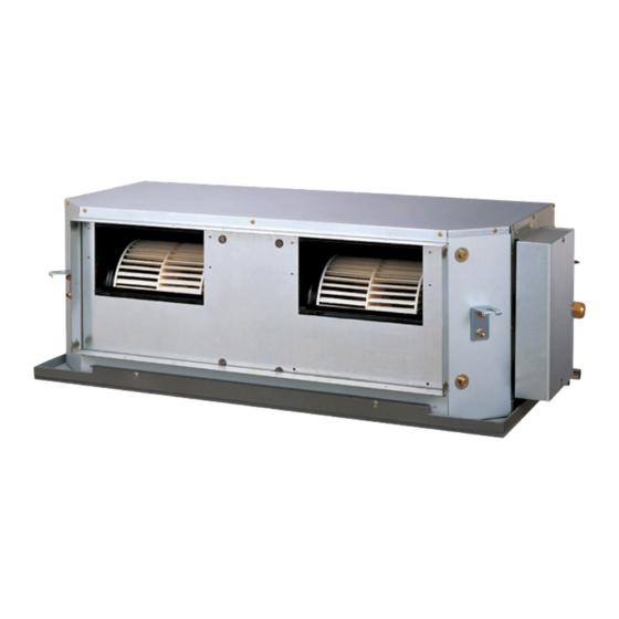
Indoor unit
ARTG54LHTC AOTG54LCTL
CO NT E NT S
SPECIFICATIONS . . . . . . . . . . . . . . . . . .
DIMENSIONS. . . . . . . . . . . . . . . . . . . . . .
CIRCUIT DIAGRAM . . . . . . . . . . . . . . . . .
INDOOR PCB CIRCUIT DIAGRAM . . . . .
ERROR DETECTION. . . . . . . . . . . . . . .
PARTS (INDOOR UNIT) . . . . . . . . . . . .
PARTS (OUTDOOR UNIT) . . . . . . . . . .
ACCESSORIES . . . . . . . . . . . . . . . . . . .
Outdoor unit
1
2
4
5
6
10
. .
17
21
24
27
Advertisement
Table of Contents

Related Manuals for Fujitsu ARTG54LHTC


Summary of Contents for Fujitsu ARTG54LHTC
-
Page 1: Table Of Contents
DUCT TYPE (50Hz) Indoor unit Outdoor unit ARTG54LHTC AOTG54LCTL CO NT E NT S SPECIFICATIONS ....DIMENSIONS..... . -
Page 2: Specifications
SP EC IF IC A T IO N S ELECTRICAL DATA NOISE LEVEL TYPE Cooling & Heating High 45 dB ARTG54LHTC INDOOR UNIT Medium 40 dB INDOOR UNIT OUTDOOR UNIT AOTG54LCTL 36 dB 14.0 kW COOLING CAPACITY Cooling 55 dB OUTDOOR UNIT 16.0 kW... -
Page 3: Dimensions
DIM E N SION S INDOOR UNIT (unit : mm) 1,260 1,192 Drain hose diameter Inside : 23.4 mm Outside : 25.4 mm 2012.08.22... - Page 4 OUTDOOR UNIT (unit : mm) air flow 2010.12.15...
-
Page 5: Refrigerant System Diagram
RE FRIG ER ANT SY ST EM DI AG RAM OUTDOOR UNIT INDOOR UNIT Refrigerant flow Refrigerant Pipe Cool Pressure 15.88mm (5/8") Check Valve Heat Strainer 3-Way Valve 4-way Valve Pressure Sensor Heat Heat Exchanger Exchanger Muffler Accumulator Compressor Refrigerant Pipe Expansion 9.52mm (3/8") Valve... -
Page 6: Circuit Diagram
DEMAND CONTROL OPTION PCB WHITE C I RC U IT DI AG RA M WHITE WHITE BROWN WHITE ORANGE WHITE BLUE WHITE YELLOW WHITE GREEN OPTION ( CONNECTOR ) REFER TO THE INSTALLATION MANUAL EARTH EX. IN EX. OUT 1 2 3 4 5 6 7 1 2 3 4 5 6 7 BLACK CN10... -
Page 7: Indoor Pcb Circuit Diagram
DC FAN MOTOR 1 DC FAN MOTOR 2 INDOOR PC B F M 1 F M 2 CONTROL UNIT CIRCUIT DIAGRAM EZ-0112MHSE CN161 FRESH AIR CN500 CN530 B02B-PAMK B5P6-VH-B B5P6-VH-B-C GREEN REACTOR ASSY WHITE BLACK L=13mH 8A CN160 DIODE BRIDGE F301 HEATER TERMINAL... - Page 8 INDOOR UNIT MAIN PCB : K09AZ-1101HSE-C1 CN70 L131 1971032-5 BLm18AG601 WHITE CN130 C130 C131 CN30 R134 - R136, R130, R131 B07B-PASK-1 0.01 B08B-PASK-1 10k <1/10W> x 5 WHITE DC VOLT IN R31, R30 WHITE <F> P_LED_OP 10k <1/10W> x 2 <F>...
- Page 9 340V W500 P I N1 YELLOW INDOOR UNIT R506 R500 - R502 PC500 10k <1/10W> POWER SUPPLY PCB 220k <1/3W> PS2561L-1-V I C500-2 1% x 3 BA2903F R507 R510, R512 C501 K09AR-0900HSE-P0 4.7k <1/10W> 1.5k <1/10W> x 2 0.01 <B> DC FAN 1 R505 I C500-1...
- Page 10 INDOOR UNIT FILTER PCB K09AX-1000HSE-FL0 W309 W310 ORANGE ORANGE W304 SECONDARY GREEN SA301 EARTH RA-362M C304 C305 0.01 0.01 <ECQU> <ECQU> VA302 470V W302 W307 <TNR> N OUT N I N WHITE WHITE R301 C301 C307 CT301 1.0M SN-PLATED <ECQU> <RN-1/2W>...
-
Page 11: Outdoor Pcb Circuit Diagram
OU TD OO R P C B C I R CUI T DI AG RAM INVERTER ASSEMBLY EZ-012CHUE EMI FILTER RFC-13 F103 F104 W100 EMI FILTER UL1015 AC250V 30A AC250V 3.15A POWER SOURCE ZCAT2132-1130 AWG12 AC240V BLACK W102 UL1015 50Hz TM101 AWG12 UL1015... - Page 12 OUTDOOR UNIT MAIN PCB - 1 K10BS-1200HUE-C1 C167, C168 R163 340V L152 330p <CH> C152 BLm31PG121 <1/10W> D200 220/ 12V-2 D3F60 JM135 15V-2 3-1747052-4 D153 YELLOW RF101L2S C214 D203 D231 AC I N R219, R220 L155 2200p + C238 1SS355 RF301B2S 1.8k <1/4W>...
- Page 13 OUTDOOR UNIT MAIN PCB - 2 K10BS-1200HUE-C1 CN12 B02B-XAKK-1-A C802 BLACK 15V-2 CN800 L800 15V-2 P_EX_OUT1 340V Q801 BL02Rn1 B6P-VH-B EX. OUT 1 <B> DTA143EUA WHITE I C10-7 D801 uLN2003A R800 RD24FM G5NB-1A <1/10W> DC FAN MOTOR 1 BLm18AG601 CN13 P_FM1_PWM R801 C800...
- Page 14 OUTDOOR UNIT TRANSISTOR PCB ( IPM ) K10AY-1201HUE-TR0 C209 - C211, C221 C222 C302 100/ 0.1 <F> L300 <F> CAL45VB470K TM303 C332 86028 TM101 D307 86028 C161 RD24FM <F> <X7R> TM304 I PM-G TM102 86028 86028 BLACK D100 C323 C305 C322 C304 C321...
- Page 15 OUTDOOR UNIT JM100 - JM102 FILTER PCB TM103 86028 K10BR-1000HUE-FL0 W111 ORANGE W112 ORANGE TM100 86028 FH106 FH107 VA100, VA101 K100 L101 L102 L100 470V <TNR> DW12D1-O (M) H-0017-2 x 2 RCH3818-022PF07 n200500K W100 RCH3818-022PF07 W102 ORANGE BLACK C104 C106 F103 0.022 0.015...
- Page 16 OUTDOOR UNIT INDICATOR PCB K10BC-1000YUE-D0 D401 SLR-325 <ORANGE> D402 SLR-325 <ORANGE> D403 SLR-325 <ORANGE> ( CN401-1 ) D404 SLR-325 <ORANGE> ( CN401-2 ) D405 SLR-325 ( CN401-3 ) <ORANGE> ( CN401-4 ) D406 SLR-325 PUMP DOWN L1 <ORANGE> ( CN401-5 ) ( CN401-6 ) D407 SLR-325 ERROR...
- Page 17 UTY-XCZZ4 DEMAND CONTROL OPTION PCB K12GV-1201HUE-CA0 I C1 0.01 PS2561L-1-V <B> R5, R4, R3, R2 4.7k 0.01 390 <1/4W> <1/4W> <B> B6 ( 7-3 ) B-XN I RK-B-2 I C2 0.01 <B> PS2561L-1-V <B> PTZ24B HP-T5338-1-4P R10, R9, R8, R7 TO MAIN PCB 4.7k 0.01...
-
Page 18: Error Detection
Indoor unit Indoor unit Wired Wired E RRO R D ETE C TION OPERATION TIMER ECONOMY OPERATION TIMER ECONOMY remote Description remote Description lamp lamp lamp lamp lamp lamp control control (green) (orange) (green) (green) (orange) (green) Serial communication error Display PCB microcomputers communication error (10) INDOOR UNIT... - Page 19 OUTDOOR UNIT TEST RUN 1. Pre-test run check items 2.1. Setting method on outdoor unit board Turn on the power of the outdoor unit and enter standby mode. Before the test operation, refer to the figure and check the following items. “POWER/MODE”...
- Page 20 OUTDOOR UNIT ERROR CODE DISPLAY You can determine the operating status by the lighting up and blinking of the LED lamp. Display when an error occurs PUMP PEAK LED display part POWER DOWN NOISE ERROR MODE (L1) (L2) (L3) (L4) (L5) (L6) Blink...
- Page 21 OUTDOOR UNIT PUMP DOWN 2. Pump down procedure WARNING (1) Check the 3-way valves (both the liquid side and gas side) are opened. Never touch electrical components such as the terminal blocks except the button on (2) Turn the power on. the display board.
-
Page 22: Parts (Indoor Unit)
PA R T S INDOOR UNIT Ref. Description Parts number Panel Top Sub Assy 9380191001 Panel Rear Sub Assy 9380205005 Panel Side R Sub Assy 9380194002 Panel Side L Sub Assy 9380203001 Pipe Panel 9380262008 Drain Pan Sub Assy 9380193005 S Drain Pan Sub Assy 9380204008 Hook... - Page 23 INDOOR UNIT Ref. Description Parts number Front Panel Assy 9380271000 Casing A 9372057018 Casing B 9372058015 Sirocco Fan 9372059029 Bracket Motor Assy 9372037010 Motor Mount Assy 9380216001 Motor Band 9378031012 Motor Band Assy 9378033016 Motor Band RFM 9378003019 Fan Motor 9603087012 2012.05.10...
- Page 24 INDOOR UNIT Ref. Description Parts number Ref. Description Parts number Seal Plate Sub Assy 9380195009 Terminal 9900433017 Control Box Assy 9380254003 Diode (Power) 0000292917 Control Box Cover Sub Assy 9380309017 Reactor Assy 9900460013 Main PCB 9708281063 Capacitor Bracket 9373155010 Power Supply PCB 9708279015 Capacitor 9704594013...
-
Page 25: Parts (Outdoor Unit)
PA R TS OUTDOOR UNIT Parts number Parts number Ref. Description Ref. Description Top Panel Sub Assy 9374417056 Motor Bracket Sub Assy 9374418169 Front Panel Sub Assy 9374414109 Motor DC Brushless 9602843039 Sevice Panel Sub Assy 9374415090 Propeller Fan Assy 9366378020 Emblem Rear 9351355005... - Page 26 OUTDOOR UNIT Control box Ref. Description Parts number Main PCB 9708690117 Indicator PCB 9708678016 Terminal 9900203023 Filter PCB 9708688015 Thermistor 9704265012 Capacitor PCB 9707257083 Choke Coil 9900624019 ACTPM 9707592016 Transistor PCB 9708647135 Heat Sink 9380358008 Thermistor (Outdoor) 9900210069 Thermistor Assy (5 pins) 9900599027 Thermistor Assy (4 pins) 9900598013...
- Page 27 OUTDOOR UNIT 4-way Valve Assy Ref. Description Parts number Expansion Valve Coil 9970098062 Expansion Valve Assy 9370947182 Strainer Assy 9372524039 Solenoid 9970113055 4-way Valve Assy 9374425273 3-way Valve Assy 9379079006 3-way Valve Assy 9379077002 Sensor 9900505080 Accumulator Assy 9375250096 Compressor Sub Assy 9374423262 Expansion Valve Assy 2012.08.23...
-
Page 28: Accessories
ACCE SSORI ES INDOOR UNIT OPTIONAL PARTS Exterior Q’ty Exterior Model Special nut A Wired remote (Large flange) 313005446653 For Air conditioner control UTY-RNNYN operation For suspending the indoor unit from ceiling Special nut A (small flange) 313005446759 Simple remote control For Air conditioner UTY-RSNYN operation... - Page 29 1208G4101...
Need help?
Do you have a question about the ARTG54LHTC and is the answer not in the manual?
Questions and answers