Fujitsu ARTG36LHTB Service Manual
Split type air conditioner duct type (50hz)
Hide thumbs
Also See for ARTG36LHTB:
- Service instruction (102 pages) ,
- Service manual (264 pages) ,
- Operating manual (40 pages)
Table of Contents
Advertisement
SPLIT TYPE
AIR CONDITIONER
DUCT TYPE (50Hz)
Indoor unit
ARTG36LHTB
C O NT E NT S
SPECIFICATIONS . . . . . . . . . . . . . . . . . .
DIMENSIONS . . . . . . . . . . . . . . . . . . . . .
CIRCUIT DIAGRAM . . . . . . . . . . . . . . . . .
INDOOR PCB CIRCUIT DIAGRAM . . . . .
ERROR DETECTION . . . . . . . . . . . . . . .
PARTS (INDOOR UNIT) . . . . . . . . . . . .
PARTS (OUTDOOR UNIT) . . . . . . . . . .
ACCESSORIES . . . . . . . . . . . . . . . . . . .
Outdoor unit
AOTG36LATT
1
2
4
5
6
10
. .
18
22
25
28
Advertisement
Table of Contents

Related Manuals for Fujitsu ARTG36LHTB


Summary of Contents for Fujitsu ARTG36LHTB
-
Page 1: Table Of Contents
AIR CONDITIONER DUCT TYPE (50Hz) Indoor unit Outdoor unit ARTG36LHTB AOTG36LATT C O NT E NT S SPECIFICATIONS ....DIMENSIONS ..... -
Page 2: Specifications
SP E C IF IC A TION S ELECTRICAL DATA NOISE LEVEL Cooling & Heating TYPE High 41 dB INDOOR UNIT ARTG36LHTB INDOOR UNIT Medium 38 dB OUTDOOR UNIT AOTG36LATT 36 dB COOLING CAPACITY 10.5 kW Cooling 51 dB OUTDOOR UNIT 12.1 kW... -
Page 3: Dimensions
DI ME NS I ON S INDOOR UNIT (Unit : mm) 1,080 1,000 1,050 Drain hose diameter Inside : 23.4 mm Outside : 25.4 mm 2010.12.09... - Page 4 OUTDOOR UNIT (unit : mm) air flow 2008.11.20...
-
Page 5: Refrigerant System Diagram
RE FRIG ER ANT SY ST EM DI AG RAM OUTDOOR UNIT INDOOR UNIT Refrigerant flow Refrigerant Pipe Cool Pressure 15.88mm (5/8") Check Valve Heat Strainer 3-Way Valve 4-way Valve Pressure Sensor Heat Heat Exchanger Exchanger Muffler Accumulator Compressor Refrigerant Pipe Expansion 9.52mm (3/8") Valve... -
Page 6: Circuit Diagram
OUTDOOR UNIT C IR CUI T D IA GR AM OPTION ( CONNECTION ) INDOOR UNIT REFER TO THE TECHNICAL MANUAL GRAY THERMISTOR GRAY ( PIPE TEMP. ) BLACK THERMISTOR BLACK ( ROOM TEMP. ) 1 2 3 1 2 3 1 2 3 1 2 3 1 2 3... -
Page 7: Indoor Pcb Circuit Diagram
IND OO R PCB C IR C UI T DIAG RAM CN8-1 BLACK THERMISTOR ( ROOM TEMP. ) B02B-XASK-1-A CN8-2 BLACK WHITE CONTROL UNIT CN7-1 B02B-XAYK-1-A CN7-2 EZ-0112KHSE YELLOW CN5-1 GRAY THERMISTOR ( PIPE TEMP. ) B02B-XAKK-1-A CN5-2 GRAY CN2-1 BLACK CN2-2 CN2-3... - Page 8 INDOOR UNIT MAIN PCB K06AK-110PHSE-C1 R1 - R3 B02B-XASK-1-A 1SS355 10k <1/10W> x 3 THERMISTOR ( ROOM TEMP. ) I C8 FLOAT SWITCH 13.5V NJM7812 B03B-PASK-1 <1/10W> B02B-XAYK-1-A 1.0k B03B-XARK-1-A <F> <1/10W> <1/10W> DC SUPPLY 1.0k 0.01 1.0k 49.9k B02B-XAKK-1-A <F>...
- Page 9 NORMAL COIL CN108 B2P3-VH-B R103 340V D108 13.5V D2FL20U <RS-2W> T101 C108 ZFT22B03-C 4700p <FNS> C113 R111 I C26-14 1000/ R104 <1/10W> 330k D102 <2W> 1SR139-600 F101 C114 0.01 C109 250V <KH> D107 220p Q101 D106 RD16 D101 <B> 2SC5354 E103 LF101 D1FL20U...
- Page 10 INDOOR UNIT INDICATOR PCB ( OPTION ) K04EI-1000HSE-D0 R201 330 <1/4W> D205 EMPG3863X GREEN R202 330 CN201 <1/4W> D206 EMAA3863X ORANGE 08 / 08 JC25 / XMR R203 330 ( OPERATE ) <1/4W> BROWN D207 EMPG3863X GREEN ( TIMER ) ( LOUVER ) ORANGE ( LOUVER )
-
Page 11: Outdoor Pcb Circuit Diagram
O UTDOOR PC B CIR C UIT DIA GR A M INVERTER ASSEMBLY THERMISTOR REACTOR REACTOR REACTOR ( HEATSINK TEMP. ) 12A 18mH EZ-01120HUE UL1007 UL1007 AWG24 AWG24 WHITE BLACK FLASH UL1015 UL1015 UL1015 UL1015 UL1015 UL1015 AWG14 AWG14 AWG14 AWG14 AWG14 AWG14... - Page 12 OUTDOOR UNIT MAIN PCB K11BU-1100HUE-C1 CN14 340V P I N101 P I N102 5V R59, R58, R57 B6 ( 7-3 ) B-XN I RK-B-2 12V-2 R101 I PS-1124 I PS-1124 10k <1/10W> x 3 REACTOR CN101 ZPR0RCH400 R77 - R79 D101 D151 CN102...
- Page 13 OUTDOOR UNIT ACTIVE FILTER PCB - 1 K11BZ-1100HUE-AF0 REACTOR L1 - L3 12A 18mH From Filter PCB TM504 TM300 TM500 DC+ OUT L1 I N W300 TM301 TM501 L2 I N W301 TM302 TM502 L3 I N W302 TM505 N OUT CT301, CT300 D351 FC-1-X x 2...
- Page 14 OUTDOOR UNIT ACTIVE FILTER PCB - 2 K11BZ-1100HUE-AF0 Jump To Page1 Jump To Page1 R530, R536 47k 1% x 2 D530 I C510-3 D470 R590 R539 C530 RB751V BA2901F DAN217U D533 R533 RB751V <F> R503 8.2k 1% R470 - R474 C591 220k <1/3W>...
- Page 15 OUTDOOR UNIT TRANSISTOR PCB K11CA-1200HUE-TR1 TM802 YELLOW P I N D908 US1J TM803 BLUE R900 R901 R902 N I N P I N801 <2.8W> <7W> <7W> L960 RGDU7M RGGS7 RGGS7 BL02Rn1 R940 - R949 DC + P I N800 0.1 <1W> 1% x 10 L900 BL02Rn1 K880...
- Page 16 OUTDOOR UNIT FILTER PCB K07AQ-0700HUE-FL0 3 Phase 380 - 415V 50Hz VA202 L200 L201 H-0017-2 x 2 820V RC3V3812-009PF05 RC3V3812-009PF05 FH200 FH201 L1 I N <TNR> 12A 0.9mH 12A 0.9mH L1 OUT TM203 TM200 P200 VA200 <NSHV4> 820V <TNR> H-0017-2 x 2 FH202 FH203 L2 I N...
- Page 17 OUTDOOR UNIT CAPACITOR PCB K07AP-0700HUE-P0 W700 W702 P OUT P I N YELLOW ORANGE R700 R702 C700 C702 660/ 660/ 450V <RS-5W> <RS-5W> 450V R701 R703 C701 C703 660/ 660/ <RS-5W> <RS-5W> 450V 450V W701 W703 N OUT N I N BLUE PURPLE 2012.04.13...
- Page 18 OUTDOOR UNIT COMMUNICATION PCB ( OPTION ) K10BQ-1200HUE-CA0 I C1 PS2561L-1-V 4.7k 0.01 <1/4W> <B> <B> R5, R4, R3, R2 TO SMART METER 390 <1/4W> x 4 0.01 TO MAIN PCB I C2 <B> PTZ24B PS2561L-1-V 4.7k ML-41-S1BYF-4P <1/4W> 0.01 B6 ( 7-3 ) B-XN I RK-B-2 <B>...
-
Page 19: Error Detection
ER R O R D ET E C TI ON WIRED REMOTE CONTROL This is possible only on a wired remote control. If an error occurs, the following display will be shown. (“Er” will appear in the set room temperature display.) Error code Unit number of indoor unit... - Page 20 OUTDOOR UNIT TEST RUN CAUTION Always turn on the power 6 hours prior to the start of the operation in order to protect the compressor. 1. Check items before performing the test run 2.1. Operating procedures for the test run Make sure to perform the test run.
- Page 21 OUTDOOR UNIT ERROR CODE DISPLAY Display when an error occurs TEST PUMP POWER LOW NOISE PEAK CUT DOWN ERROR MODE (L1) (L2) (L3) (L4) (L5) (L6) (L7) Blinks (Hi-speed) Check that the ERROR LED blinks, and then short-press the [ENTER] switch once. Display mode : ON The number of blinks of the LED indicates the type of error.
- Page 22 2. Pump down procedure OUTDOOR UNIT PUMP DOWN (Refrigerant collecting operation) (1) Check the 3-way valves (both at the liquid side and gas side) are opened. (2) Turn the power on. Perform the following procedures to collect the refrigerant when moving the indoor unit or outdoor unit TEST PUMP POWER...
-
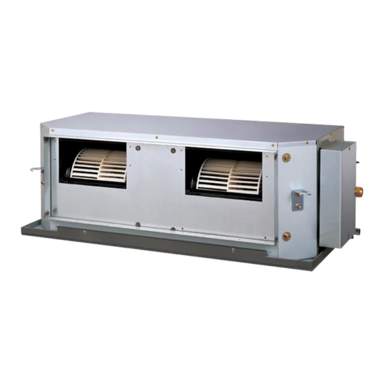
Page 23: Parts (Indoor Unit)
P A RT S INDOOR UNIT Ref. Description Parts number Plate Top Sub Assy 9372576014 Connector : white black Kit (Panel Front Sub Assy) 9372637029 Kit (Panel Rear Sub Assy) 9372636022 Room Thermistor 9703299216 Evaporator Sub Assy 9372584033 Pipe Thermistor 9703297113 Drain Pan Assy 9372579015... - Page 24 INDOOR UNIT Ref. Description Parts number Panel Fan Assy 9372035009 Bracket Motor Assy 9372037010 Motor Mount Assy 9380216001 Motor Band Assy 9378033016 Motor Band 9378031012 RFM Motor Band 9378003019 Motor, DC Brushless 9603086015 Casing A 9372057018 Casing B 9372058015 Sirocco Fan 9372059029 2012.06.13...
- Page 25 INDOOR UNIT Ref. Description Parts number Control Box Assy 9374854035 Power Supply PCB 9707398397 Main PCB 9709245095 Reactor 9707457018 Terminal 3P 9703345012 Terminal 3P 9306489045 Remote Control 9318593020 2012.06.13...
-
Page 26: Parts Outdoor Unit
PARTS OUTDOOR UNIT Ref. Description Parts number Ref. Description Parts number Top Panel Sub Assy 9374417032 Reactor Assy 9900641016 Front Panel Sub Assy 9374414130 Motor, DC Brushless 9602843046 Sevice Panel Sub Assy 9374415076 Propeller Fan Assy 9366378020 Emblem Rear 9351355005 Condenser A Sub Assy 9374420261 Pipe Cover Front... - Page 27 OUTDOOR UNIT 4-way Valve Assy Ref. Description Parts number Expansion Valve Coil 9900190057 Expansion Valve Assy 9370947182 Strainer Assy 9372524039 Solenoid 9970113024 4-way Valve Assy 9374425273 3-way Valve Assy 9379079006 3-way Valve Assy 9379077002 Sensor 9900505011 Accumulator Assy 9375250096 Expansion Valve Assy Compressor Sub Assy 9374423286 2012.03.16...
- Page 28 OUTDOOR UNIT (yellow) (white) (red) (white) (connector : blue) Ref. Description Parts number Main PCB 9709249017 Filter PCB 9707609011 Active Filter PCB 9709008010 Capacitor PCB 9707608014 Transistor PCB 9709010020 Reactor Assy 9900481018 (red) Terminal 9900428082 Compressor Thermistor 9900516000 Discharge Thermistor 9900515003 (red) Thermistor (Heat Exchanger Mid)
-
Page 29: Accessories
ACCESS OR IE S INDOOR UNIT OPTIONAL PARTS Name and Shape Q'ty Application Part number Parts name Model No. Application Wired UTY-RNNYM For air conditioner operation Special nut A 313005446653 remote control (large flange) For suspending the indoor unit from ceiling Special nut B Simple UTY-RSNYM... - Page 30 1204G4067...
Need help?
Do you have a question about the ARTG36LHTB and is the answer not in the manual?
Questions and answers