
Related Manuals for Fujitsu ARTG54LHTC


Summary of Contents for Fujitsu ARTG54LHTC
- Page 1 AIR CONDITIONER Duct type DESIGN & TECHNICAL MANUAL INDOOR ARTG54LHTC OUTDOOR AOTG54LCTL...
-
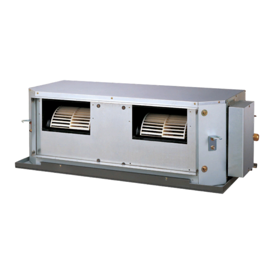
Page 2: Indoor Unit
1. INDOOR UNIT DUCT TYPE : ARTG54LHTC DTR_AR056E_05 2016.04.27... -
Page 3: Table Of Contents
CONTENTS 1. INDOOR UNIT FEATURE ......................01 - 01 WIRED REMOTE CONTROLLER ........... 01 - 04 2-1. AR-WDD1E (Option: UTY-RVNYN) ............01 - 04 2-2. AR-WAF1E (Option: UTY-RNNYN) ............01 - 07 SPECIFICATIONS ..................01 - 10 DIMENSIONS ....................01 - 11 WIRING DIAGRAMS .................. -
Page 4: Feature
FEATURE MODEL „ „ ARTG54LHTC / AOTG54LCTL FEATURES „ „ Significantly improved EER/COP „ Significantly improved Hi-efficiency is realized by the use of a ALL-DC components, inverter technology, and large heat exchanger. Cooling Heating Cooling EER Heaing COP Previous increase! 3.00... - Page 5 Individual air conditioning for each room by „ Zone Control System (Option) Zone Control System manage the air conditioning of each room (Zone) by the air conditioning system with forced draft air duct to reach the pleasant room temperature. Refer to Design & Technical Manual "ZONE CONROL SYSTEM" (DTR-OP006E). Control system „...
- Page 6 • 2-Remote controllers control Control locally and from a remote point is possible using 2-remote controllers. Transmission cable Refrigerant pipe Indoor unit Remote controller cable (Primary) (Secondary) Wired R.C. Wired R.C. * For 2-wired type remote controllers, specify a Primary and a Secondary remote controller. * The timer function of the remote controller specified the Secondary cannot be used.
-
Page 7: Wired Remote Controller
WIRED REMOTE CONTROLLER 2-1. AR-WDD1E (Option: UTY-RVNYN) FEATURES „ „ Large and full-dot liquid crystal screen ¾ „ Screen with backlight can be seen even in the dark ¾ „ Wide and large keys easy to press, user-intuitive arrow key ¾... - Page 8 Set temperature upper and lower limit setting „ During Cooling During Heating ● The set temperature range can be (°C) (°C) set for each operation mode. (Cooling / Heating / Auto) Weekly 1 (°C) 22°C Original temp. Original temp. Lower limit Upper limit Of f setting range...
- Page 9 FUNCTIONS „ „ 1 Display panel (with backlight) 6 Screen switch button (Right) 2 Screen switch button (Left) 7 Power indicator 3 Menu button 8 On / Off button 4 Cancel button 9 Enter button 5 Cursor button SPECIFICATION „ „...
-
Page 10: Ar-Waf1E (Option: Uty-Rnnyn)
2-2. AR-WAF1E (Option: UTY-RNNYN) FEATURES „ „ Various timer setup (ON/OFF/WEEKLY) are possible. ¾ „ Equipped with weekly timer as standard function. ¾ „ (Possible to set START/STOP time to operate twice each day of the week.) When setting up a timer, operation mode and a temperature setup ¾... - Page 11 Easy-to-understand operation Simple installation „ „ Components are compatible with standard switch boxes. Flat back surface allows equipment to be installed wherever it is needed. Timer Operation area area European switch box [Variable timer control] The operation/display sections are zoned according to time and operation, enabling variable programming JIS box to match application.
- Page 12 FUNCTIONS „ „ START/STOP button Pressed to start and stop operation. Set temperature button Selects the setting temperature. MODE button Selects the operating mode (AUTO, HEAT, FAN, COOL, DRY). FAN button Selects the fan speed (AUTO, LOW, MED, HIGH). ECONOMY button Turns the economy efficient mode on and off.
- Page 13 SPECIFICATIONS DUCTED MODEL Type INVERTER HEATPUMP Model name ARTG54LHTC Power source 1Ø 240 V~ 50 Hz Available voltage range 198 - 264 V Cooling STAR RATING INDEX 10 STAR standard Heating 14.0 Rated Btu/h 47,800 Cooling 6.2-15.2 Min - Max.
-
Page 14: Dimensions
DIMENSIONS MODEL : ARTG54LH „ „ (Unit : mm) - (01 - 11) -... - Page 15 INSTALLATION PLACE „ „ (Unit : mm) Installation by which service space is made on top of the unit (recommended). 350 or more (Service space) 500 or more Service access Installation by which service is carried out from the bottom of the unit. 20 or more (Service...
-
Page 16: Wiring Diagrams
WIRING DIAGRAMS MODEL : ARTG54LH „ „ - (01 - 13) -... -
Page 17: Capacity Table
CAPACITY TABLE 6-1. COOLING CAPACITY This table is created using the rated capacity. MODEL : ARTG54LH „ „ 59.2 Indoor temperature °CDB °CWB °CDB 13.04 12.32 2.77 14.53 12.40 2.82 15.02 13.48 2.83 16.01 13.52 2.86 16.51 14.60 2.87 17.50 14.54 2.90 18.49 15.49 2.93... -
Page 18: Heating Capacity
6-2. HEATING CAPACITY This table is created using the rated capacity. MODEL : ARTG54LH „ „ 59.2 Indoor temperature °CDB °CDB °CWB 12.79 4.91 12.48 5.01 12.18 5.11 11.88 5.21 11.57 5.31 14.22 4.91 13.88 5.01 13.54 5.11 13.20 5.21 12.86 5.31 15.76... -
Page 19: Fan Performance And Capacity
FAN PERFORMANCE AND CAPACITY MODEL : ARTG54LH „ „ Q-h Characteristic curve Hi(SP mode4) Hi(SP mode3) Hi(SP mode2) Hi(SP mode1) (Normal SP mode) Normal SP mode Upper limit Normal SP mode Lower limit Med(Normal SP mode) Lo(Normal SP mode) 1,000 1,500 2,000 2,500... -
Page 20: Operation Noise
OPERATION NOISE 8-1. NOISE LEVEL CURVE Condition Static pressure : 60Pa MODEL : ARTG54LH „ „ Static pressure mode : Normal Cooling Heating „ „ NC-65 NC-65 NC-60 NC-60 NC-55 NC-55 NC-50 NC-50 NC-45 NC-45 HIGH HIGH NC-40 NC-40 NC-35 NC-35 NC-30 NC-30... -
Page 21: Sound Level Check Point
8-2. SOUND LEVEL CHECK POINT Measuring duct Measuring duct Set the static pressure as rating in this area - (01 - 18) -... - Page 22 ELECTRIC CHARACTERISTICS Model name ARTG54LH Voltage 240~ Power supply Frequency Max Operating Current (Indoor unit) Connection cable 1.5 (Min.) Wiring spec. (Indoor unit to outdoor unit) Limited wiring length Note: Wiring specification 1. Selected sample (Selected based on Japan Electrotechnical Standard and Codes Committee E0005) 2.
-
Page 23: Safety Devices
SAFETY DEVICES Model Protection form ARTG54LH Circuit protection Current fuse (PCB) 250V 3.15A Current fuse 250V 20A Fan motor protection OFF: 115±15°C Thermal protection program ON: 70°C - (01 - 20) -... -
Page 24: External Input & Output
EXTERNAL INPUT & OUTPUT INPUT OUTPUT Connector REMARKS CONTROL INPUT — CN103 — OPERATION STATUS CN100 See external — ERROR STATUS CN101 input/output settings for details. — FRESH AIR CONTROL CN161 — AUXILIARY HEATER CN160 11-1. EXTERNAL INPUT CONTROL INPUT (Operation/Stop or Forced stop) „... - Page 25 ● When function setting is "Forced stop" mode Input signal Forced stop Command Normal Operation Indoor unit Stop Remote controller Remote control operation invalidity Parts (Optional) „ Model name UTD-ECS5A Wire (External input) - (01 - 22) -...
-
Page 26: External Output
11-2. EXTERNAL OUTPUT OPERATION STATUS OUTPUT „ „ An air conditioner operation status signal can be output. Circuit diagram example „ Indoor unit Connected unit control PC board Connector Ex.)Relay unit Ex.)Display 24V DC Relay power supply *10 m Signal Field supply * Make the distance from the PC board to the connected unit within 10m. - Page 27 ERROR STATUS OUTPUT „ „ An air conditioner condition normal/error status signal can be output. Circuit diagram example „ Indoor unit Connected unit control PC board Connector Ex.)Relay unit Ex.)Display 24V DC Relay power supply *10 m Signal Field supply * Make the distance from the PC board to the connected unit within 10m.
- Page 28 FRESH AIR CONTROL OUTPUT „ „ A signal linked to air conditioner indoor fan ON can be output. * However, signal becomes OFF during cold air prevention control operation. Circuit diagram example „ Indoor unit Connected unit control PC board Ex.) Fan Ex.) Relay unit 12 V...
- Page 29 AUXILIARY HEATER OUTPUT „ „ Corresponding indoor units: slim duct type, duct type, high static pressure duct type A signal is outputed from Connector when indoor fan and compressor turn on under heating operation. * Signal output performance specifications are as Tr-Ts shown on the right Tr-Ts = -1°C...
- Page 30 CAUTION Please locate external a heater between the indoor unit and the ductwork. Please be sure to use delay control of a fan. External Indoorunit Heater Supply air Return air Parts (Optional) „ Model name UTD-ECS5A Wire (Heater output) - (01 - 27) -...
-
Page 31: Function Setting
FUNCTION SETTING 12-1. INDOOR UNIT INDOOR UNIT DIP-SW50 Remote controller address setting JM40 Setting prohibited Jumper Wire JM41 JM42 Fan delay setting SWITCH POSITION „ „ MAIN PCB JM42 JM41 JM40 SW50 - (01 - 28) -... - Page 32 DIP-SW SETTING „ „ Remote controller address setting (SW50) „ A number of indoor units can be operated at the same time using a single remote controller. Set the unit number of each indoor unit using the DIP switches on the indoor unit circuit board. (See the following table.) The DIP switches are normally set to make the unit number 00.
-
Page 33: Indoor Unit (Setting By Remote Controller)
12-2. INDOOR UNIT (Setting by remote controller) • The function settings of the control of the indoor unit can be changed by this procedure according to the installation conditions. Incorrect settings can cause the indoor unit malfunction. • After the power is turned on, perform the “FUNCTION SETTING” according to the installation conditions using the remote controller. - Page 34 5) Select the [Function No.] with pressing the [Cursor button Function setting Mo 10:00 (Left/Right)], and select the Function No. to be set with R.C. Function Setting pressing the [Cursor button (Up/Down)]. address Cancel: Version Error history 6) Select the [Setting No.] with pressing the [Cursor button Function setting Mo 10:00 (Left/Right)], and select the Setting No.
-
Page 35: Function Setting Method (For Ar-Waf1E (Option: Uty-Rnnyn))
12-2-2. FUNCTION SETTING METHOD (for AR-WAF1E (Option: UTY-RNNYN)) Setting method „ (1) Press the set temperature buttons ( ) and fan control button simultaneously for more than 5 seconds to enter the function setting mode. SU MO TU WE TH FR SA (2) Press the SET BACK button to select the indoor unit number. -
Page 36: Contents Function Setting
12-2-3. CONTENTS FUNCTION SETTING 1. Filter sign • Select appropriate intervals for displaying the filter sign on the indoor unit according to the estimated amount of dust in the air of the room. If the indication is not required, select "No indication" (03). ( ... - Page 37 6. Room temperature sensor switching function • (Only for wired remote controller) When using the Wired remote controller temperature sensor, change the setting to "Both" (01). ( . . .Factory setting) Setting description Function number Setting value Indoor unit ...
-
Page 38: Wired Remote Controller
12-3. WIRED REMOTE CONTROLLER 12-3-1. AR-WDD1E (Option: UTY-RVNYN) Memory backup setting Switch Dual remote controller setting Switch position „ DIP Switch setting „ ● Memory backup setting Set to ON to use batteries for the memory backup. If batteries are not used, all of settings stored in memory will be deleted if there is a power failure. -
Page 39: Ar-Waf1E (Option: Uty-Rnnyn)
12-3-2. AR-WAF1E (Option: UTY-RNNYN) Can not be used. (Do not change) Dual remote controller setting Can not be used. (Do not change) DIP SW Can not be used. (Do not change) Can not be used. (Do not change) Memory backup setting SWITCH POSITION „... -
Page 40: Optional Parts
OPTIONAL PARTS 13-1. CONTROLLER Exterior Parts name Model No. Summary Large and full-dot liquid crystal Wired remote screen, wide and large keys UTY-RVNYN controller easy to press, user-intuitive arrow key. Unit control is performed by wired remote controller. Wired remote controller is Wired remote UTY-RNNYN attached in one as accessories. - Page 41 2. OUTDOOR UNIT SINGLE TYPE : AOTG54LCTL DTR_AO114E_04 2016.04.27...
- Page 42 CONTENTS 2. OUTDOOR UNIT FEATURE ······························································································ 02 - 01 2. SPECIFICATIONS ·············································································· 02 - 03 DIMENSIONS ······················································································· 02 - 04 4. INSTALLATION PLACE ··································································· 02 - 05 4-1. SINGLE OUTDOOR UNIT INSTALLATION ········································· 02 - 05 4-2. MULTIPLE OUTDOOR UNIT INSTALLATION ·····································...
-
Page 43: Feature
FEATURE FEATURES „ „ Energy saving technology (ALL DC) „ DC twin rotary compressor DC fan motor DC twin rotary compressor Efficiency in all load regions is good. Especially good performance from low to medium at normal operation. High efficiency compressor motor High Miniaturized, low noise,... - Page 44 Space saving „ Compact size High performance has been realized with a compact outdoor unit. Due to the compact size of the outdoor unit, the installation space required has been reduced allowing for a wider selection on installation locations. 4-directions piping connection „...
-
Page 45: Specifications
SPECIFICATIONS Type INVERTER HEATPUMP Model name AOTG54LCTL Power source 240 V~ 50 Hz Available voltage range 198-264 V Starting current 18.4 Cooling 1917 (6900) Airflow l/s (m rate Heating 1903 (6850) Type × Q'ty Propeller × 2 Motor output Cooling Sound pressure level Heating dB(A) -
Page 46: Dimensions
DIMENSIONS MODEL : AOTG54LC „ „ (Unit : mm) Top view Terminal blocks 3-way valve ( Gas ) Ø28 (Cable port) Ø28 (Cable port) Pipe port Pipe port Pipe port Front view Side view Rear view Detail A Pipe & cable port 51.5 Bottom view - (02 - 04) -... -
Page 47: Installation Place
INSTALLATION PLACE 4-1. SINGLE OUTDOOR UNIT INSTALLATION WHEN THE UPWARD AREA IS OPEN „ „ (Unit : mm) Obstacles at front and Obstacles at rear Obstacles at rear and Obstacles at front only sides only only rear only 1000 or more 1000 or more WHEN AN OBSTRUCTION IS PRESENT ALSO IN THE UPWARD AREA „... -
Page 48: Multiple Outdoor Unit Installation
4-2. MULTIPLE OUTDOOR UNIT INSTALLATION WHEN THE UPWARD AREA IS OPEN „ „ (Unit : mm) Obstacles at rear only Obstacles at front only Obstacles at front and rear only 1500 or more 1500 or more WHEN AN OBSTRUCTION IS PRESENT ALSO IN THE UPWARD AREA „... -
Page 49: Refrigerant Circuit
REFRIGERANT CIRCUIT MODEL : AOTG54LC „ „ - (02 - 07) -... -
Page 50: Wiring Diagrams
WIRING DIAGRAMS MODEL : AOTG54LC „ „ - (02 - 08) -... -
Page 51: Capacity Compensation Rate For Pipe Length And Height Difference
CAPACITY COMPENSATION RATE FOR PIPE LENGTH AND HEIGHT DIFFERENCE MODEL : AOTG54LC „ „ Pipe length (m) COOLING 0.871 0.837 0.803 0.768 0.717 Û 1 0.921 0.886 0.851 0.816 0.781 0.729 Indoor unit is 0.971 0.936 0.901 0.865 0.830 0.794 0.741 upper than 0.988 0.975 0.940 0.904 0.869 0.833 0.798 0.744 outdoor unit. -
Page 52: Pipe Size Selection & Limitation
PIPE SIZE SELECTION & LIMITATION MODEL : AOTG54LC „ „ I.U. •I.U.: Indoor unit •L1: Max. piping length •H1: Max. height difference < Indoor unit to outdoor unit > Pipe Liquid pipes 9.52 (3/8) 12.70 (1/2) diameter 15.88 19.05 15.88 19.05 Gas pipes (5/8) -
Page 53: Additional Charge Calculation
ADDITIONAL CHARGE CALCULATION MODEL : AOTG54LC „ „ Refrigerant type R410A Refrigerant amount 3,450 IF ADDITIONAL REFRIGERANT IS REQUIRED „ „ • When the piping is longer than pre-charge length, additional charging is necessary. • For the additional amount, see the table below. Additional charging amount I.U. -
Page 54: Air Flow
AIR FLOW MODEL : AOTG54LC „ „ Cooling „ Number of MODEL rotations Air flow (r.p.m.) 6900 Upper fan AOTG54LC 1917 Lower fan 4062 Heating „ Number of MODEL rotations Air flow (r.p.m.) 6850 Upper fan AOTG54LC 1903 Lower fan 4033 - (02 - 12) -... -
Page 55: Operation Noise
OPERATION NOISE 11-1. NOISE LEVEL CURVE MODEL : AOTG54LC „ „ Cooling Heating „ „ NC-65 NC-65 NC-60 NC-60 NC-55 NC-55 NC-50 NC-50 NC-45 NC-45 NC-40 NC-40 NC-35 NC-35 NC-30 NC-30 NC-25 NC-25 NC-20 NC-20 NC-15 NC-15 1,000 2,000 4,000 8,000 1,000 2,000... -
Page 56: Sound Level Check Point
11-2. SOUND LEVEL CHECK POINT Air Flow Microphone Microphone - (02 - 14) -... -
Page 57: Electric Characteristics
ELECTRIC CHARACTERISTICS Model name AOTG54LC Voltage 240~ Power supply Frequency *1) Max. operating current 23.5 Circuit breaker current *2) Wiring spec. Power cable 6.0 (Min) *1) The maximum current is the total current of indoor unit and outdoor unit. *2) Wiring spec. : Selected sample (Selected based on Japan Electrotechnical Standard and Codes Committee E0005) - (02 - 15) -... -
Page 58: Safety Devices
SAFETY DEVICES Model Protection form AOTG54LC Current fuse (Main PCB) 250V 3.15A "250V 10A" × 2 Circuit protection Current fuse (Filter PCB) 250V 30A 250V 3.15A OFF:150±15°C Fan motor protection Thermal protector ON:120±15°C Thermal protection program OFF:110°C (Compressor temp.) ON:80°C Compressor protection Thermal protection program... -
Page 59: External Input & Output
EXTERNAL INPUT & OUTPUT Input Output Connector Remarks Low noise mode ― CN10 Peak cut mode ― CN11 See external input/output settings ― Error status CN12 for details. ― Compressor status CN13 14-1. EXTERNAL INPUT ON/OFF of the "Low noise mode" and "Peak cut mode" functions can be specified by external signal. - Page 60 PEAK CUT MODE „ „ • Operation that suppressed the current value can be performed by means of the following on- site work. The air conditioner is set to the Peak cut mode when closing the contact input of a commercial ON/OFF switch to a connector on the outdoor control PC board.
-
Page 61: External Output
14-2. EXTERNAL OUTPUT ERROR STATUS OUTPUT „ „ • An air conditioner error status signal is produced when a malfunction occurs. Circuit diagram example „ Outdoor unit Connected unit control PC board Connector Power supply 1) Power supply ●Voltage (Chart sign=Vcc) : DC 24V or less 2) Load Load ●... - Page 62 COMPRESSOR STATUS OUTPUT „ „ • Compressor operation status signal is produced when the compressor is running. Circuit diagram example „ Outdoor unit Connected unit control PC board Connector Power supply 1) Power supply ●Voltage (Chart sign=Vcc) : DC 24V or less 2) Load Load ●...
-
Page 63: Function Setting
FUNCTION SETTING Caution Discharge the static electricity from your body before setting up the push buttons. Never touch the terminals or the patterns on the parts that are mounted on the board. 15-1. FIELD SETTING SWITCHES The positions of the switches on the outdoor unit control board are shown in the figure below. LED lamps Push buttons... -
Page 64: Setting Method
15-2. SETTING METHOD • Stop the operation of air conditioner before this setting. 15-2-1. LOW NOISE MODE LED lamp part (1) Switch to “Local setting mode” by pressing [MODE] button (SW1) for 3 seconds or more. (2) Confirm (POWER / MODE) blinks 9 times, and press [ENTER] button (SW3). PUMP POWER LOW NOISE... -
Page 65: Peak Cut Mode
15-2-2. PEAK CUT MODE LED lamp part (1) Switch to “Local setting mode” by pressing [MODE] button (SW1) for 3 seconds or more. (2) Confirm (POWER / MODE) blinks 9 times, and press [ENTER] button (SW3). PUMP POWER LOW NOISE PEAK CUT DOWN ERROR... -
Page 66: Optional Parts
OPTIONAL PARTS Exterior Parts name Model No. Summary Use to operate the External input External connect UTY-XWZXZ3 and output function of Outdoor unit. - (02 - 24) -...
Need help?
Do you have a question about the ARTG54LHTC and is the answer not in the manual?
Questions and answers