
Related Manuals for Xterra 16468451US


Summary of Contents for Xterra 16468451US
-
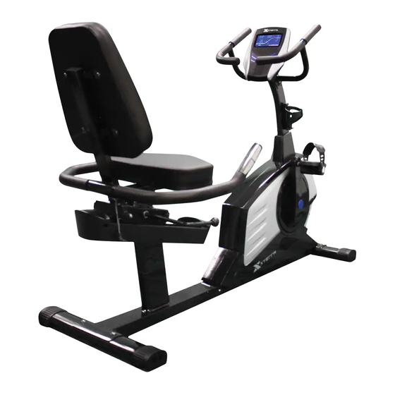
Page 1: Recumbent Cycle
OWNER`S MANUAL Model No. RECUMBENT CYCLE 16468451US Xterra Recumbent Cycle CAUTION: You must read and understand this owner’s manual before operating unit. Keep this manual for future reference. -
Page 2: Table Of Contents
TABLE OF CONTENTS Manufacturer’s Limited Warranty ……………………. …… 2 Safety Precautions………….………………………………. 3 Before you begin …………………………………………….. 4 Pre-assembly Check List…………………………………… 5 Hardware Packing List……………………………………… 6 Assembly Instruction……………………………………….. 7-10 Monitor Instruction……...…………………………………… 11-17 User Direction………………………………………………. Maintenance ………………………………………………… 19-20 Parts List / Diagram ………………………………………… 21-25 Trouble Shooting …………………………………………….. -
Page 3: Manufacturer's Limited Warranty
Manufacture’s One-Year Limited Warranty Your Xterra Cycle is warranted for one year from the date of purchase against defects in material when used for the purpose intended, under normal conditions and provided it receives proper care. Any part found defective or missing will be sent at no cost when returned in accordance with the terms of this warranty. -
Page 4: Safety Precautions
SAFETY PRECAUTIONS Thank you for purchasing our product. Even though we go to great efforts to ensure the quality of each product we produce, occasional errors and /or omissions do occur. In any event should you find this product to have either a defective or a missing part please contact us for a replacement. This product has been designed for home use only. -
Page 5: Before You Begin
BEFORE YOU BEGIN Thank you for selecting the revolutionary Xterra exercise bike. Cycling is an effective exercise for increasing cardiovascular fitness, building endurance, and toning the body. The exercise bike provides an impressive selection of features designed to make your workouts at home more effective and enjoyable. -
Page 6: Pre-Assembly Check List
PRE-ASSEMBLY CHECK LIST NO:1 NO:7 NO:32 NO:4 NO:34 NO:23L/R NO:5L NO:5R NO:37 NO:6/100 NO:33 NO:8 NO:19L/R NO:97 NO:2 NO:3 PART NO. DESCRIPTION Q’TY Main frame Front stabilizer Rear stabilizer Front stabilizer Left handlebar Right handlebar 6/100 Computer/Audio wire Rear support tube Cover for front post 19L/R Left / Right pedal... -
Page 7: Hardware Packing List
HARDWARE PACKING LIST Description Drawing Part No. Allen screw M8*16 Curved washer Φ8*20 Flat washer Φ8*Φ17 Allen screw M8*20 Leveling pad Ball nut Carriage bolt M8*45 Domed nut M8 Box wrench Allen key 6mm Customer Service 1-888-707-1880 or email customerservice@dyaco.ca Dyaco Canada Inc. -
Page 8: Assembly Instruction
ASSEMBLY INSTRUCTION This manual is designed to help you easily assemble, adjust and use this machine. Please read this manual carefully. For the sake of familiarizing yourself with the parts identified in the instruction, first study the overview drawing. Set all parts in a clear area on the floor and remove the packing material. Refer to the parts list for help to identify the parts. - Page 9 Step 3 Insert front post (4) into the front post cover (8). Connect the extension computer wire (9) to the lower computer wire (18). Connect front extension hand pulse wire (10) to the middle extension hand pulse wire (17). ...
- Page 10 Step 4 Thread the ball end cap (35) to the quick release handle (29). Note thread on clockwise. Pull up the brake bracket (94) and the quick release handle (29). Slide the seat support bracket (32) into the rear support tube (7). Secure by pressing down the brake bracket (94) and quick release handle (35).
- Page 11 Step 5 Connect the rear extension hand pulse wire (22) to the hand pulse wire (42). Attach the rear handlebar (37) to the seat support bracket (32). Secure using two carriage bolts (43), two curved washers (15) and two domed nuts (44). ...
-
Page 12: Monitor Instruction
MONITOR INSTRUCTIONS FUNCTION BUTTON START/STOP: Press to start or stop your exercise program. Press to start body fat measurement. Press UP to increase the target values. Press UP to increase the tension level while you are exercising. Press UP to select your desired program. DOWN: Press DOWN to decrease the preset target values. - Page 13 Gripped pulse Display’s the user’s current heart rate in beats per minute during the workout. Both hands must hold the gripped pulse for a heart rate reading during your workout. You may preset your target pulse. The computer will alarm to remind you as soon as your current heart rate has achieved at the preset figure.
- Page 14 Program Introduction & Operation: Manual Program: Manual P1 is a manual program. User can start exercise by pressing START/STOP key. The default resistance level is 7. Users may exercise in any desirous of resistance level (Adjusting by UP/DOWN keys during the workout) with a period of time or a number of calories or a certain distance.
- Page 15 User Setting Program: User 1, User 2, User 3, User 4 Program 14 to 17 is the user setting program. Users are free to create the values in the order of TIME, DISTANCE, CALORIES and the resistance level in 10 columns. The values and profiles will be stored in the memory after setup.
- Page 16 8. Press the START/STOP key to begin exercise. Body Fat Program: Body Fat Program 23 is a special program design to calculate users’ body fat ratio and to offer a specific loading profile for users. There are 3 body types divided according to the FAT% calculated. Type1: BODY FAT% >...
- Page 17 PRESET PROGRAM PROFILES: PROGRAM 1 PROGRAM 2 PROGRAM 3 PROGRAM 4 MANUAL STEPS HILL ROLLING PROGRAM 5 PROGRAM 6 PROGRAM 7 PROGRAM 8 VALLEY FAT BURN RAMP MOUNTAIN PROGRAM 9 PROGRAM 10 PROGRAM 11 PROGRAM 12 INTERVAL SRANDOM PLATEAU FARTLEK PROGRAM 13 PRECIPICE USER SETTING PROGRAM...
- Page 18 HEART RATE PROGRAM PROFILES: PROGRAM 18 55% H.R.C. PROGRAM 19 65% H.R.C. PROGRAM 20 75% H.R.C. PROGRAM 21 85% H.R.C. PROGRAM 22 TARGET H.R.C. BODY FAT TEST PROGRAMS: PROGRAM 23 BODY FAT (STOP MODE) BODY FAT (START MODE) One of the Following Six Profiles Will Display Automatically after Measuring Your BODY FAT: Workout Time: 40 minutes Workout Time: 40 minutes Workout time: 20 minutes...
-
Page 19: User Direction
USER DIRECTION HOW TO USE THE EXERCISE BIKE SEAT CUSHION HOW TO ADJUST THE SEAT The seat can be adjusted forward or backward to the position that is the most comfortable. To adjust the seat, pull up the quick release bar, slide the seat to the the desired position and press down the quick release bar. -
Page 20: Maintenance
MAINTENANCE HOW TO ADJUST THE REED SWITCH If the console does not display correct feedback, the reed switch should be adjusted. To adjust the reed switch, the run disc (48) must first be removed. Remove the left pedal (19L) from the run disc (48). Remove the end cap for run disc (46) and flange screw (47). - Page 21 HOW TO ADJUST THE DRIVE BELT If you can feel the pedals slip while you are pedaling, even when the resistance is adjusted to the highest level, the drive belt may need to be adjusted. To adjust the drive belt, the right chain cover (56R) must first be removed.
-
Page 22: Parts List / Diagram
PARTS LIST Key No. Part Description 6845101 Main frame 6845102 Front stabilizer 6845103 Rear stabilizer 6845104 Front post 6845105L Left handlebar 6845105R Right handlebar 6845106 Computer 6845107 Rear support tube 6845108 Front post cover 6845109 Middle computer wire 6845110 Front extension hand pulse wire 6845111 Upper foam grip for stationary handlebar 6845112... - Page 23 Key No. Part Description 6845130 Lower foam grip for handlebar 6845131 End cap for seat support bracket □53.5*23.5 6845132 Seat support bracket 6845133 Seat cushion 6845134 Back cushion 6845135 Ball end cap 6845136 End cap for rear handlebar 6845137 Rear handlebar 6845138 Upper hand pulse sensor 6845139...
- Page 24 Key No. Part Description 6845165 Bearing 6845166 Hex head bolt M6*25 6845167 Hex head nut M6 6845168 Spring for magnet assembly 6845169 Spring for idler wheel 6845170 Eye bolt 6845171 Nut M8 6845172 Idler wheel 6845173 Powder spacer 6845174 Pulley 6845175 Nylon nut M6 6845176...
- Page 25 DIAGRAM Customer Service 1-888-707-1880 or email customerservice@dyaco.ca Dyaco Canada Inc. ©2014...
- Page 26 Customer Service 1-888-707-1880 or email customerservice@dyaco.ca Dyaco Canada Inc. ©2014...
-
Page 27: Trouble Shooting
TROUBLE SHOOTING Problem Cause Correction No pedal movement detected Start pedaling Monitor does not display Ensure the computer wires are Computer wires not connected connected properly at the upright and the computer Ensure the computer wires are Sensor wire not connected connected properly at the upright and the computer No speed or distance... -
Page 28: Training Guideline
Checks Be sure batteries are new and electronic connection are clean and tight. Check that seat nuts are secure, check before each workout. Check that pedals are tight, pedals can work loose over time. Check that stabilizer bolts are tight, check before each workout this. ... -
Page 29: Stretching
Progression As your become fitter, a higher intensity of exercise is required to create an overload and therefore provide continued improvement Overload This is where you exercise at a level above that which can be carried out comfortably. The intensity, duration and frequency of exercise should be above the training threshold and should be gradually increased as the body adapts to the increasing demands. - Page 30 work quite comfortably a little above that suggested for your age group. The following table is a guide to those who are keeping fit. Here we are working at about 80% of maximum. Target heart Rate 10 Second Count Beats per Minute Don’t push yourself too hard to reach the figures on this table.
-
Page 31: Stretching
The rest period required between strength training exercises may vary from person to person. This will depend mostly on your level of fitness and the program you have chosen. Rest between exercises by all means, but do not allow this to exceed two minutes. Most people manage with half minute to one minute rest periods. - Page 32 INNER THIGH STRETCH TOE TOUCHES Sit with the soles of your feet together with your Slowly bend forward from your waist, letting knees pointing outward. Pull your feet as close your back and shoulders relax as you stretch Into your groin as possible. Gently push your toward your toes.
Need help?
Do you have a question about the 16468451US and is the answer not in the manual?
Questions and answers
How can I raise the seat on this bike please
To raise the seat on the Xterra bike (part number 16468451US), lift the quick release bar, slide the seat to the desired position, and then press down the quick release bar to secure it.
This answer is automatically generated