
Related Manuals for Xterra FB360


Summary of Contents for Xterra FB360
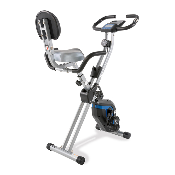
- Page 1 Model: 16204993600 FB360 FOLDING BIKE OWNER’S MANUAL TABLE OF CONTENTS PLEASE CAREFULLY READ THIS ENTIRE MANUAL BEFORE OPERATING YOUR NEW FOLDING BIKE...
-
Page 2: Table Of Contents
Before You Begin ....................3 Important Safety Instructions ................4 FB360 Assembly Instructions ................7 Monitor operation .................... 14 User Direction ....................15 General Maintenance ..................16 Exploded View Diagram ..................18 Parts List ......................19 Manufacturer’s Limited Warranty ..............29 ATTENTION THIS FOLDING BIKE IS INTENDED FOR RESIDENTIAL USE ONLY AND IS WARRANTED FOR THE APPLICATION. -
Page 3: Important Safety Instructions
Thank you for choosing the Xterra FB360 Folding Bike. We take great pride in producing this quality product and hope it will provide many hours of quality exercise to make you feel better, look better, and enjoy life to its fullest. It's a proven fact that a regular exercise program can improve your physical and mental health. - Page 4 WARNING: Before beginning any exercise program consult your physician. This is especiallyimportant for individuals over the age of 35 or persons with pre-existing health problems. Read all instructions before using any fitness equipment. We assume no responsibility from persona FB360 PRE-ASSEMBLY CHECK LIST...
- Page 5 Support Tube front and back Seat Support Tube Handlebar / Computer Front Stabilizer Rear Stabilizer Seat Pedal ( L/R ) 74/75 Upper back support tube/ lower back support tube Rear Handlebar Back Cushion Remote-control Holder Hardware Bag Manual FB360 ASSEMBLY PACK CHECKLIST...
-
Page 6: Fb360 Assembly Instructions
Spring Washer Allen Screw M8x45L Allen Key Hex head wrench Note: Above parts are all the parts needed to assemble this machine. Before you start to assemble, please check the hardware packing to make sure they are included. FB360 ASSEMBLY INSTRUCTIONS... - Page 7 STEP 1 FRONT STABILIZER AND REAR STABILIZER Pre-assembled on Main Frame: 1 Lock pin (#11) Pre-assembled on Front & Rear Stabilizer: 4 Curved washers (#13) 4 Domed nuts (#14) 1. Pull out the lock pin (11) from the front support tube (01) and adjust the front support tube (01) to the correct position then insert lock pin (11) to secure the front support tube (01).
- Page 8 1. Connect the left and right pedals (09L) & (09R) to their appropriate crank arm (15L&15R). The right pedal is on the right-hand side of the cycle as you sit on it. 2. Note that the right pedal (09R) should be threaded on clockwise and the left pedal (09L) on counter-clockwise.
- Page 9 1 Adjustment Knob (#10) Pre-assembled on seat: 3 Flat Washers (#16) 3 Nylon Nuts (#17) 1. Remove 3 flat washers (16) and 3 nylon nuts (17) underneath the seat (07). Attach the seat (07) to the seat support tube (03), tighten with 3 flat washers (16) and 3 nylon nuts (17). 2.
- Page 10 STEP 4 Back Cushion 2 Nylon Nuts (#17) 2 Flat Washers (#55) 2 Carriage Bolts (#78) 4 Allen Screws (#80) 4 Spring Washers (#84) 1. Attach the lower back support tube (74) to the upper back support tube (03), tighten using 2 nylon nuts (17), 2 flat washers (55) and 2 carriage bolts (78).
- Page 11 STEP 5 REAR HANDLEBAR 2 Allen Screws (#81) 2 Curved washers (#13) 1. Attach the rear handlebar (76) to the lower back support tube (74), tighten using 2 curved washers (13) and 2 Allen screws (81). STEP 6 CONSOLE...
- Page 12 Pre-assembled on rear support tube: 4 screw set (#12) 1. Remove the pre-installed 4 Screw Sets (12) from the Handlebar Tube (04). 2. Connect the middle sensor wire (19) to the wire on the back of the console (08). 3. Insert the Handlebar Tube (04) to the Rear Support Tube (02), secure with the 4 Screw Sets (12). Please insert two ‘’AAA”...
- Page 13 STEP 7 REMOTE-CONTROL HOLDER Pre-assembled on Main Frame: 2 Allen Screws (#82) 1. Remove 2 screws (82) from the support tube, attach the remote-control holder (89) onto the main frame, and tighten using 2 screws (82).
-
Page 14: Monitor Operation
MONITOR OPERATION GETTING FAMILIAR WITH THE CONTROL PANEL Key Functions FUNCTIONAL BUTTON: MODE – Push down to select functions. SET - To Set the consumer movement of time, distance, calories and hand pulse. RESET -For resetting consumer movement of time, distance, calories and hand pulse. FUNCTIONS AND OPERATIONS 1. -
Page 15: User Direction
AUTO SCAN Every 6 seconds TIME 0:00’~99:59’ CURRENT SPEED 0.0~999.9 KM/H(MILE/H) FUNCTION TRIP DISTANCE 0.00~999.9 KM (MILE) CALORIES 0.0~999.9 CAL ODOMETER 0.0 ~ 9999 KM(MILE) PULSE RATE 40~240 BPM BATTERY TYPE 2pcs of SIZE –AAA OPERATING TEMPERATURE 0°C ~ +40°C STORAGE TEMPERATURE -10°C ~ +60°C USER DIRECTION... - Page 16 performed once a week. However, some checks should be made before each workout, and are indicated as such below. Checks • Check that seat nuts are secure, check before each workout. • Check that pedals are tight, pedals can work loose over time. •...
- Page 17 If you can feel the pedals slip while you are pedaling, even when the resistance is adjusted to the highest level, the drive belt may need to be adjusted. The first step to remove the end cap ( 57) and flange nut (49 ), then use the special tools remove the right / left crank.
-
Page 18: Exploded View Diagram
EXPLODED VIEW DIAGRAM... -
Page 19: Parts List
PARTS LIST PART NUMBER DESCRIPTION 9936001 Front support tube 9936002 Rear support tube 9936003 Seat support tube 9936004 Handlebar tube 9936005 Front stabilizer 9936006 Rear stabilizer 9936007 Seat 9936008 Computer 9936009L Pedal L 9936009R Pedal R 9936010 Adjustment knob M12 9936011 Lock pin φ8x70L 9936012... - Page 20 PART NUMBER DESCRIPTION 9936038 Nylon nut M10 9936039 Flywheel 9936040 Axle for pulley 9936041 Idler wheel 9936042 Fixed plate 9936043 Hex head nut M10 9936044 Hex head nut M6 9936045 Nut M10 9936046 Screw M6x10L 9936047 Tension knob 9936048 Grommet 9936049 Flange nut M10 9936050...
- Page 21 PART NUMBER DESCRIPTION 9936078 Carriage Bolt M8x50L 9936079 Allen Screw M8x80L 9936080 Allen Screw M8x45L 9936081 Allen Screw M8x40L 9936082 Screw M4x10L 9936083 Plastic Washer φ20xφ8.5 9936084 Spring Washer 9936085 End cap □15x30 9936086 End cap □30 9936087 Foam Grip for Rear Handlebar 9936088 Protective Cover 9936089...
- Page 22 TROUBLESHOOTING Problem Cause Solution Install batteries properly in Batteries not installed monitor Monitor does not display Monitor is defective Replace the monitor Ensure the sensor wires are connected together properly Sensor wire not connected No speed or distance also with a connection at the displays back of the monitor on the monitor...
- Page 23 TRAINING GUIDELINES EXERCISE Exercise is one of the most important factors in the overall health of an individual. Listed among its benefits are: Increased capacity for physical work (strength endurance) Increased cardiovascular (heart and arteries/veins) and respiratory efficiency Decreased risk of coronary heart disease ...
- Page 24 Progression As your become fitter, a higher intensity of exercise is required to create an overload and therefore provide continued improvement Overload This is where you exercise at a level above that which can be carried out comfortably. The intensity, duration and frequency of exercise should be above the training threshold and should be gradually increased as the body adapts to the increasing demands.
- Page 25 The following table is a guide to those who are “starting fitness”. Target heart Rate 10 Second Count Beats per Minute Pulse Count The pulse count (on your wrist or carotid artery in the neck, taken with two index fingers) is done for ten seconds, taken a few seconds after you stop exercising.
- Page 26 Muscle Soreness For the first week or so, this may be the only indication you have that you are on an exercise program. This, of course, does depend on your overall fitness level. A confirmation that you are on the correct program is a very slight soreness in most major muscle groups.
- Page 27 STRETCHING Stretching should be included in both your warm up and cool down and should be performed after 3-5 minutes of low intensity aerobic activity or callisthenic type exercise. Movements should be performed slowly and smoothly, with no bouncing or jerking. Move into the stretch until slight tension, not pain, is felt in the muscle and hold for 20-30 seconds.
- Page 28 TOUCHES INNER THIGH STRETCH Slowly bend forward from your waist, Sit with the soles of your feet together letting your back and shoulders relax as you with your knees pointing outward. Pull stretch toward your toes. Reach down as far your feet as close into your groin as as you can and hold for 15 counts.
-
Page 29: Manufacturer's Limited Warranty
MANUFACTURER’S LIMITED WARRANTY Dyaco Canada Inc. warrants all its folding bike parts for a period of time listed below from the date of retail sale, as determined by sale receipt. Dyaco Canada Inc.’s responsibilities include providing new or remanufactured parts, at Dyaco Canada Inc.’s option. The warranty period applies to the following components: Limited Warranty Frame...
Need help?
Do you have a question about the FB360 and is the answer not in the manual?
Questions and answers