Table of Contents
Advertisement
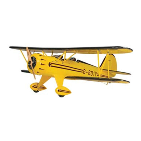
SPECIFICATIONS
Wingspan:
72 in
[1830mm]
2
1384 in
Wing Area:
[89.2 dm
WARRANTY
WARRANTY
Great Planes
Great Planes
Model Manufacturing Co.
Model Manufacturing Co. guarantees this kit to
®
®
®
be free from defects in both material and workmanship at the
be free from defects in both material and workmanship at the
date of purchase. This warranty does not cover any component
date of purchase. This warranty does not cover any component
parts damaged by use or modification. In no case shall Great
Planes' liability exceed the original cost of the purchased kit.
Further, Great Planes reserves the right to change or modify this
warranty without notice.
In that Great Planes has no control over the final assembly or
material used for final assembly, no liability shall be assumed nor
accepted for any damage resulting from the use by the user of
the final user-assembled product. By the act of using the
user-assembled product, the user accepts all resulting liability.
If the buyer is not prepared to accept the liability associated
with the use of this product, the buyer is advised to return
READ THROUGH THIS MANUAL BEFORE STARTING CONSTRUCTION. IT CONTAINS IMPORTANT
INSTRUCTIONS AND WARNINGS CONCERNING THE ASSEMBLY AND USE OF THIS MODEL.
© 2010 Hobbico
®
, Inc.
Weight:
12.75– 13.75 lb
[5780– 6230 g]
Wing
21– 23 oz/ft
2
]
Loading:
[64– 70 g /dm
guarantees this kit to
INSTRUCTION
Length:
Radio:
Engine:
2
2
]
this kit immediately in new and unused condition to the
this kit immediately in new and unused condition to the
place of purchase.
place of purchase.
To make a warranty claim send the defective part or item to
Hobby Services at the address below:
Hobby Services
3002 N. Apollo Dr. Suite 1
Champaign IL 61822 USA
Include a letter stating your name, return shipping address, as
much contact information as possible (daytime telephone
number, fax number, e-mail address), a detailed description of
the problem and a photocopy of the purchase receipt. Upon
receipt of the package the problem will be evaluated as quickly
as possible.
Champaign, Illinois
(217) 398-8970, Ext 5
airsupport@greatplanes.com
MANUAL
56.5 in
[1435mm]
4-Channel with 7 std servos
.91 cu in [15cc] 2-stroke
1.20 cu in [20cc] 4-stroke
25-30cc gas
GPMA1295 Mnl
Advertisement
Table of Contents

Related Manuals for GREAT PLANES Waco YMF-5


Summary of Contents for GREAT PLANES Waco YMF-5
- Page 1 3002 N. Apollo Dr. Suite 1 Champaign IL 61822 USA In that Great Planes has no control over the final assembly or material used for final assembly, no liability shall be assumed nor Include a letter stating your name, return shipping address, as...
-
Page 2: Table Of Contents
KIT INSPECTION....... .4 Waco YMF-5 ARF visit the Great Planes web site at www. -
Page 3: Decisions You Must Make
(1) 12" [300mm] servo extension (HCAM2711) ❏ (1) 30" [760mm] servo extension (EMOM0129) ❏ This is a partial list of items required to finish the Waco YMF-5 (1) 21" [533mm] Y-harness (HCAM2500) ❏ that may require planning or decision making before starting 1x or 2x if no computer radio) 6"... -
Page 4: Optional Supplies And Tools
Frequently you can study photos in following steps ❏ Tap handle (GPMR8120) to get another view of the same parts. ❏ Pliers with wire cutter (HCAR0625) ® • The Waco YMF-5 is factory-covered with Top Flite ❏ ® Hobbico Heavy Duty Diagonal Cutter 7" (HCAR0627) ® MonoKote film. -
Page 5: Ordering Replacement Parts
Order No. Description provided by your hobby dealer or mail-order company. GPMA4065 Fuselage Set To locate a hobby dealer, visit the Great Planes web site GPMA4066 Top Wing Set at www.greatplanes.com. Choose “Where to Buy” at the GPMA4067 Bottom Wing Set bottom of the menu on the left side of the page. -
Page 6: Prepare For Assembly
PREPARE FOR ASSEMBLY ❏ 2. Use a 5/64" [2mm] drill bit to drill the outermost servo arm hole on all four aileron servos. Before you begin assembling your model, use a covering iron Bottom Wing Assembly set to a medium temperature (about 250° F [121° C]) to tack down any loose or wrinkled covering. - Page 7 screw holes with thin CA. Let the CA cure and reinstall the screws. Remember that you are going to set up a left side servo and a right side servo. ❏ ❏ ❏ ❏ 6. Attach a 16" [405mm] servo lead extension to the 3.
- Page 8 ❏ ❏ ❏ ❏ 9. Using a 90° builder’s square or triangle, draw a 13. Fit the clevis to the outer hole of the control horn. 1/2" [12.7mm] long line on the aileron straight back from the With the aileron servo and the aileron centered, mark the servo arm.
-
Page 9: Top Wing Assembly
cures. Use three rubber bands on the dowels to hold the L.E. together. Put two rubber bands on the top side of the wing and two on the bottom side with the bolts half way through the holes. ❏ 21. Use paper towels and some denatured alcohol to clean up any excess epoxy that is squeezed out of the joint. - Page 10 pushrod wire leaving 1/4" [6.4mm] of wire and fit the pushrod to the outer hole of the servo arm. Secure the pushrod at the servo arm with a nylon Faslink. Adjust the pushrod length at the clevis. Secure the clevis with the silicone retainer. 140°...
- Page 11 ❏ 11. Two joiners are needed to join the top left wing to the ❏ 14. Do the same for the left wing, coating the joiners and center wing section and two joiners are needed to join the ribs with epoxy. When you’re ready to slide the left wing onto right wing to the center section.
-
Page 12: Assemble The Fuselage
inside. With the fairings up against the fuselage, wrap some ASSEMBLE THE FUSELAGE 1/8" EZ-Mask tape (GPMR1000) or a narrow strip of regular masking tape about 1/16" [1.6mm] above the bottom edge of each fairing. Main Landing Gear Installation ❏ 4. -
Page 13: Cabane Strut Installation
Cabane Strut Installation ❏ 7. File a 1/4" [6.4mm] wide flat spot at a distance 3/16" [4.8mm] from the base of the axle. File another one that is 1-9/16" [40mm] from the base of the axle. ❏ ❏ 8. Install a 3-1/2" [89mm] wheel onto each axle using two 1. -
Page 14: Horizontal Stabilizer, Tailwheel & Rudder Installation
Horizontal Stabilizer, Tailwheel and Rudder Installation ❏ 1. Once again, you’ll need to have your epoxy supplies nearby and ready. Set the model down on its wheels. Fit the short 165mm x 10mm aluminum tube into the L.E. hole in the fuselage and the long 270mm x 10mm tube into the T.E. - Page 15 ❏ 4. Remove the two 3mm wheel collars and the tailwheel from the tailwheel assembly. Grind two 1/8" [3.2mm] flat spots on the axle so that one is centered 1/8" [3.2mm] from the support arm and one is centered 7/8" [22.2mm] from the support arm.
-
Page 16: Pushrod, Control Horn & Servo Installation
Pushrod, Control Horn and Servo Installation ❏ 1. Turn the model over. Slide two 36" [914mm] pushrods into the left and right elevator pushrod guide tubes so that the unthreaded end goes to the servo tray inside of the fuse. ❏... - Page 17 ❏ 5. Install a nylon clevis and a silicone retainer on each ❏ 8. Use a piece of masking tape to tape each elevator elevator pushrod. Be sure to screw the pushrod into the clevis counterbalance to the stabilizer so that the elevators will far enough so that at least 1/8"...
-
Page 18: Glow Engine Installation
❏ 11. Fit two 3/16" [4.8mm] wheel collars onto the elevator pushrod wires. Use a drop of thread locking compound on the screw threads and fit two 6-32 x 1/4" SHCS. With both ❏ 15. Mark the rudder pushrod at the servo arm hole and elevators centered, tighten the collar locking screws to hold make a 90°... -
Page 19: Hook Up The Throttle
[25.4mm] adjustable clamps. With the engine in position, use ™ a Great Planes Dead Center Engine Mount Hole Locator ❏ 2. Dry fit the 24" [610mm] gray outer pushrod tube in (GPMR8130) to drill four pilot holes or mark the position of the hole you just drilled. - Page 20 ❏ 3. Fit a screw-lock pushrod connector to the outermost hole on short servo arm. Choose the arm that is 90° to the servo case at 1/2 throttle. Clip off the unused servo arms. Use a nylon retainer to secure the pushrod connector to the servo arm.
-
Page 21: Install The Fuel Tank
Install the Fuel Tank ❏ 3. Fit fuel lines to the tank and route the lines through the ❏ hole in the firewall as you fit the tank. Be careful to make 1. Cut two pieces of glow fuel line and attach to clunks. sure that the vent line is pointed toward the top of the model. -
Page 22: Gasoline Engine Installation
GASOLINE ENGINE INSTALLATION This section will cover the installation of a DL Engines DLE- 30cc gasoline engine. Other similarly sized gas engines can be used, but be careful to space the ignition equipment as far away as possible from the radio equipment. If you are installing a different engine, please respect the firewall to prop washer dimension of 6-11/16"... -
Page 23: Hook Up The Throttle
Hook Up the Throttle ❏ 4. Position the inside end of the pushrod tube about 4" [102mm] from the servo. Cut the pushrod tube 3/8" [9.5mm] ❏ 1. Using a long drill bit, drill a 3/16" [4.8mm] hole through forward of the firewall. Fit the wooden pushrod tube standoff the firewall in line with the engine’s throttle arm. -
Page 24: Install The Fuel Tank
Secure the lines and the clunks with four small 4" [102mm] tie wraps. Build up the fuel tank as shown with the vent line pointing to the top of the tank. You may want to use a felt tip pen to mark which direction the vent line is pointed so that you know where the top of the tank is when you’re installing the tank. -
Page 25: Install The Ignition Unit
Install the Ignition Unit ❏ 1. Build the ignition unit and battery tray using a small builder’s square or triangle to set the upright pieces 90° to the base. Use 5-minute epoxy to assemble the tray. Fuelproof the tray with a mixture of epoxy and denatured alcohol. ❏... -
Page 26: Final Assembly
Note: Positioning the switch here is important so that it is away from heat and gasoline. Great Planes Install the ignition switch and the charge jack. Connect the ignition battery to the switch and the switch to the ignition unit. - Page 27 and charge lead in the front or rear cockpit floor. Be careful to choose a place where the switch will not interfere with the servos or pushrods underneath. Note: If you will be installing a pilot figure, temporarily fit the pilot figure to the cockpit so that you know where to position the switch and charge jack.
-
Page 28: Cowl And Propeller Installation
away the standard attachment point and use the alternate Cowl and Propeller Installation point. A typical glow engine installation should not require trimming of the cowl rings. Use a drop of thread locking The cowl installation shown here is for the DLE-30 gas engine. compound on the screw threads. - Page 29 ❏ Placing a piece of masking tape on the cowl and the fuselage 11. Cut a 16" x 16" [406mm x 406mm] piece of Great Planes with an index mark on them will be helpful. Trim away material Plan Protector film (GPMR6167) or some MonoKote backing until the cowl is resting on the flange of the cowl center tool film or plastic food wrap.
- Page 30 fiberglass. Apply a continuous bead of this on the front side of the joint between the cowl and the ring. This will reinforce the cowl ring. Note: You may apply epoxy to the rear side of the cowl ring, but this must be a very thin layer without much of a fillet at the joint of the cowl to ring.
-
Page 31: Install The Wheel Pants And Fairings
Install the Wheel Pants and Fairings ❏ 4. Using R/C-56, glue the wing bolt backing plate to the wing. Then, install the bottom wing using the two nylon wing bolts. Hold the top of the fillets in place up against the ❏... -
Page 32: Cockpit Options
Cockpit Options Pilot Installation (Optional) ❏ 1. To install a pilot figure, please purchase a Great Planes 1/5th scale pilot (GPMQ9115). Trim 3/8" off of the base of the pilot figure so the figure measures 4" for the rear pilot and 3-1/2"... -
Page 33: Finishing The Model
Finishing the Model ❏ 3. Install the two interplane struts using eight 4-40 x 1/2" [12.7mm] SHCS, eight #4 flat washers, and eight #4 lock nuts. Note: Be careful not to install the struts upside down. The bolt holes on bottom side of the struts are spread farther apart than the top (from front to back). -
Page 34: Apply The Decals
4. Use a piece of soft balsa or something similar to squeegee remaining water from under the decal. Apply the rest of the Use a Great Planes AccuThrow, a ruler, or an inclinometer decals the same way. to accurately measure and set the control throw of each ❏... -
Page 35: Balance The Model (C.g.)
Balance the Model (C.G.) At this stage the model should be in ready-to-fly condition with all of the systems in place including the prop, cowl, and pilot figure(s). ❏ 2. With all parts of the model installed (ready to fly) and an empty fuel tank, put your fingers on the balance points you just marked and suspend the model from these points. -
Page 36: Preflight
Do not throw anything into the propeller of a running engine or motor. We use a Top Flite Precision Magnetic Prop Balancer (TOPQ5700) in the workshop and keep a Great Planes Fingertip Prop Balancer (GPMQ5000) in our flight box. -
Page 37: Ama Safety Code
AMA SAFETY CODE ( CHECK LIST EXCERPTS Read and abide by the following excerpts from the Academy During the last few moments of preparation your mind may of Model Aeronautics Safety Code. For the complete Safety be elsewhere anticipating the excitement of the fi rst fl ight. Code refer to Model Aviation magazine, the AMA web site or Because of this, you may be more likely to overlook certain the Code that came with your AMA license. -
Page 38: Flying
Gain as much The Waco YMF-5 is a great-flying model that flies smoothly speed as your runway and flying site will practically allow and predictably. - Page 39 One final note about flying your model. Have a goal or flight IGNITION SWITCH AND ERNST plan in mind for every flight. This can be learning a new CHARGE JACK TEMPLATE maneuver(s), improving a maneuver(s) you already know, or learning how the model behaves in certain conditions (such as on high or low rates).
Need help?
Do you have a question about the Waco YMF-5 and is the answer not in the manual?
Questions and answers