Table of Contents
Advertisement
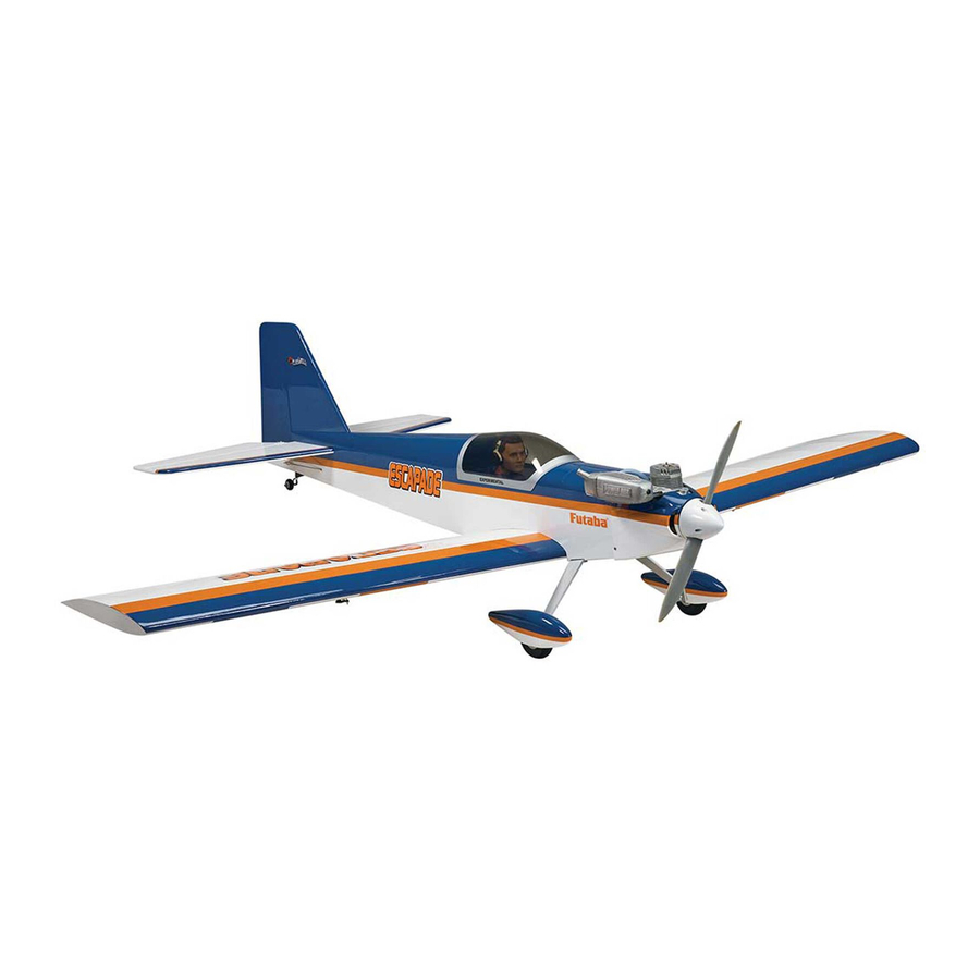
SPECIFICATIONS
Wingspan: 68 in [1725 mm]
Wing Area: 813 in
Wing Loading: 23−26 oz/ft
[70−79 g /dm
WARRANTY
Great Planes
®
Model Manufacturing Co. guarantees this kit to
be free from defects in both material and workmanship at the
date of purchase. This warranty does not cover any component
parts damaged by use or modification. In no case shall Great
Planes' liability exceed the original cost of the purchased kit.
Further, Great Planes reserves the right to change or modify this
warranty without notice.
In that Great Planes has no control over the final assembly or
material used for final assembly, no liability shall be assumed nor
accepted for any damage resulting from the use by the user of
the final user-assembled product. By the act of using the
user-assembled product, the user accepts all resulting liability.
If the buyer is not prepared to accept the liability associated
with the use of this product, the buyer is advised to return
READ THROUGH THIS MANUAL BEFORE STARTING CONSTRUCTION. IT CONTAINS IMPORTANT
INSTRUCTIONS AND WARNINGS CONCERNING THE ASSEMBLY AND USE OF THIS MODEL.
®
Entire Contents © 2010 Hobbico,
Inc. All rights reserved.
I N S T R U C T I O N
Length: 58.5 in [1485mm]
2
2
Weight: 8.25 − 9 oz [3740−4080 g]
[52.4 dm
]
Radio: 4-channel radio system with 5 servos
2
2
]
Engine: .61−.95 in
Electric Motor: RimFire™ .80, 60A ESC
3
[10 –15.5cc] two-stroke, .91 – 1.20 in
this kit immediately in new and unused condition to the
place of purchase.
To make a warranty claim send the defective part or item to
Hobby Services at the address below:
3002 N. Apollo Dr. Suite 1
Champaign IL 61822 USA
Include a letter stating your name, return shipping address, as
much contact information as possible (daytime telephone
number, fax number, e-mail address), a detailed description of
the problem and a photocopy of the purchase receipt. Upon
receipt of the package the problem will be evaluated as quickly
as possible.
airsupport@greatplanes.com
™
M A N U A L
Battery: Two 3S 5000mAh 11.1V LiPo
3
[15 – 20 cc] four-stroke
Hobby Services
Champaign, Illinois
(217) 398-8970, Ext 5
GPMA1201 Mnl
Advertisement
Table of Contents

Related Manuals for GREAT PLANES ESCAPADE .61


Summary of Contents for GREAT PLANES ESCAPADE .61
- Page 1 3002 N. Apollo Dr. Suite 1 Champaign IL 61822 USA In that Great Planes has no control over the final assembly or material used for final assembly, no liability shall be assumed nor Include a letter stating your name, return shipping address, as...
-
Page 2: Table Of Contents
For the latest technical updates or manual corrections to the Protect Your Model, Yourself & Others… Escapade .61 ARF visit the Great Planes web site at www. Follow These Important Safety Precautions greatplanes.com. Open the “Airplanes” link, then select the 1. -
Page 3: Decisions You Must Make
local hobby shop has information about clubs in your area Following are the other suggested items if powering your whose membership includes experienced pilots. Escapade with an electric motor: 6. While this kit has been fl ight tested to exceed normal use, ❍... -
Page 4: Additional Items Required
For example 4-40 × 3/4" [19mm]. To locate a hobby dealer, visit the Great Planes web site at This is a 4-40 SHCS that is www.greatplanes.com. Select “Where to Buy” in the menu 3/4"... -
Page 5: Kit Contents
3002 N Apollo Drive, Suite 1 GPMA4136 Wing Escapade .61 ARF personal check to: Champaign IL 61822 GPMA4137 Horizontal Stabilizer Escapade .61 ARF GPMA4138 Vertical Stabilizer .61 Escapade ARF Be certain to specify the order number exactly as listed in the GPMA4139 Canopy Escapade .61 ARF... -
Page 6: Tighten The Covering
TIGHTEN THE COVERING Refer to the separate instruction sheet titled How To Tighten Covering On ARF Models. Follow the instructions to tighten the covering. If you prefer to get started on assembly right away, the tightening process could be done later (but it is usually easiest to do while the model is still in separate pieces). - Page 7 Left Wing Right Wing ❏ ❏ 5. Note the position of the servo arms in the sketch. Cut off the other three unused arms from the aileron servo arm. ❏ ❏ ❏ ❏ 6. Thread a nylon clevis approximately 20 turns onto the 8.
-
Page 8: Assemble The Fuselage
ASSEMBLE THE FUSELAGE Install the Elevator and Rudder ❏ 1. Cut the balsa block free from the stabilizer opening with a hobby knife. ❏ 10. Slide the wings together on the wing tube. Temporarily mount the nylon strap to the wings with two #4 x 3/8" [9.5mm] Phillips screws. - Page 9 ❏ 5. Even though the nuts used on the fi n wires are locking nuts, a drop of threadlocker on the threads is recommended. Add a drop of threadlocker to the threads of the wires. Then, tighten the assembly to the fuselage with a #4 fl at washer, a #4 lock washer and a 4-40 lock nut on each rod.
- Page 10 ❏ 12. Place the elevator servo into the servo tray in the fuselage. Orient it as shown in the photo. Same as you did ❏ 8. Thread the nylon clevis onto the pushrod wire 20 turns. with the rudder servo, connect the elevator servo to your Slide the elevator and rudder pushrods into the guide tubes receiver and battery and turn on the radio.
-
Page 11: Mount The Main Landing Gear
❏ ❏ 2. Mount an axle to each landing gear, securing it with the 15. Remove the nylon Faslink from the pushrod wire and axle nut. Be sure that the fl at spot on the end of the axle is remove the wire from the servo arm. -
Page 12: Removing The Fuselage Hatch
Removing the Fuselage Hatch Some of the assembly that follows may require that you Proceed to “Mount the Glow Engine” if you will not be remove the hatch on the top of the fuselage. The following installing the electric motor. explains removing it. - Page 13 ❏ 5. Use a side cutter or moto-tool to cut the screws fl ush mounting holes for the Great Planes 60 amp ESC (GPMM1850). with the surface of the plywood. Drill a 1/16" [1.6mm] hole through each of the marks. Insert and then remove a #2 x 3/8"...
-
Page 14: Mount The Glow Engine
❏ ❏ 2. Place your engine on the mount, sliding the mount halves 4. Use a Great Planes Dead Center ™ Hole Locator together or apart to fi t the engine. Now you may tighten the (GPMR8130) or a sharpened wire to mark the location of mount bolts the rest of the way. -
Page 15: Install The Cowl (Optional)
❏ The method may need slight modifi cation depending on your 5. Use a Great Planes Dead Center Hole Locator radio. Please review these instructions before determining if (GPMR8130) or a sharpened wire to mark the location of you will install the cowl. -
Page 16: Mount The Fuel Tank Or Battery
Mount the Battery ❏ 7. Cut the fi berglass cowl as needed to allow the cowl to fi t over the engine and the muffl er. Once you are satisfi ed with ❏ the fi t of the cowl, drill two 1/16" [16mm] holes into each side 1. -
Page 17: Mount The Fuel Tank
Mount the Fuel Tank ❏ 3. Slide the Velcro straps into the slots in the tray as shown. When you insert the battery into the fuselage, place the battery against the Velcro you installed on the tray and tighten the Velcro straps around the battery. -
Page 18: Hook Up The Throttle
HOOK UP THE THROTTLE ❏ 1. Install a servo arm onto the throttle servo. Place the throttle servo into the fuselage. Slide the 20" [508mm] pushrod wire through the hole in the fi rewall and into the fuselage. Align Vent Tube the hole at the end of the arm with the pushrod wire. -
Page 19: Four-Stroke Hookup
Proceed to “Final Assembly” on page 20 Four-Stroke Hookup 90° Pushrod Connector Carburetor Throttle Guide Tube Firewall ❏ 1. Install the screw-lock connector onto the throttle arm as shown. Cut the threaded portion off of the 20" [508mm] Clevis Throttle pushrod and then bend a 3/4"... -
Page 20: Final Assembly
FINAL ASSEMBLY Install the Fuel Line Vent / Overflow (Connect to fitting on Muffler) One line is for Fueling and Defueling. The other line goes to the Carburetor. It doesn’t matter which line goes where because they are both the same inside the fuel tank. ❏... -
Page 21: Install The Propeller And Spinner
Install the Propeller and Spinner ❏ 1. Install the spinner back plate and propeller onto the engine. Temporarily install the prop washer and prop nut. Fit the spinner cone to the spinner back plate. The screws for the spinner cone need to align with the screw holes in the back plate. -
Page 22: Get The Model Ready To Fly
❏ 2. Position decal on the model where desired. Holding the These two 1500mAh batteries (both 11.1V) are decal down, use a paper towel to wipe most of the water away. being joined in PARALLEL. The result will be ❏ one 11.1V, 3000mAh battery. -
Page 23: Set The Control Throws
4-CHANNEL RADIO SETUP (STANDARD MODE 2) RIGHT AILERON RUDDER MOVES UP MOVES LEFT AILERON RIGHT MOVES DOWN Use a small box or something similar to prop up the fuselage until the wings and horizontal stabilizers are level. FULL ELEVATOR THROTTLE MOVES DOWN ❏... -
Page 24: Balance The Model (C.g.)
2 oz. [57g] weight). If spinner weight is not practical or be successful. If you value your model and wish to enjoy it is not enough, or if tail weight is required, use Great Planes for many fl ights, DO NOT OVERLOOK THIS IMPORTANT “stick-on”... -
Page 25: Balance The Model Laterally
We use a Top Flite Precision Magnetic Prop Balancer fuse under the TE of the fi n. Do this several times. (TOPQ5700) in the workshop and keep a Great Planes ❏ Fingertip Prop Balancer (GPMQ5000) in our fl ight box. -
Page 26: Ama Safety Code
To stop a glow engine, cut off the fuel supply by closing CHECK LIST off the fuel line or following the engine manufacturer’s recommendations. Do not use hands, fi ngers or any other During the last few moments of preparation your mind may body part to try to stop the engine. -
Page 27: Flying
❏ bring the model back into the pits. Top off the fuel, then check 16. Balance your propeller (and spare propellers). all fasteners and control linkages for peace of mind. ❏ 17. Tighten the propeller nut and spinner. ❏ Remember to takeoff into the wind. When you’re ready, point 18. -
Page 28: Landing
One fi nal note about fl ying your model. Have a goal or fl ight Landing plan in mind for every fl ight. This can be learning a new maneuver(s), improving a maneuver(s) you already know, To initiate a landing approach, lower the throttle while on the or learning how the model behaves in certain conditions downwind leg.
Need help?
Do you have a question about the ESCAPADE .61 and is the answer not in the manual?
Questions and answers